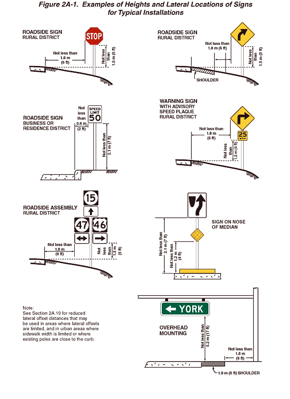
Figure 2A-1. Examples of Heights and Lateral Locations of Signs for Typical Installations
This figure shows seven examples of heights and lateral locations of signs for typical installations.
The first illustration is labeled "Roadside Sign Rural District." The roadway is shown with no shoulder. The sign in this example is a Stop sign. The distance from the bottom edge of the sign to the level of the edge of the pavement is shown as a dimension not less than 1.5 m (5 ft). The distance between the edge of the pavement and the near edge of the sign is shown as a dimension not less than 1.8 m (6 ft).
The second illustration is labeled "Roadside Sign Rural District." The road is shown with a shoulder. The sign in this example is a Curve Warning sign. The distance from the bottom edge of the sign to the level of the edge of the travel lane at the inside edge of the shoulder is shown as a dimension not less than 1.5 m (5 ft). The distance between the outside edge of the shoulder and the near edge of the sign is shown as a dimension not less than 1.8 m (6 ft).
The third illustration is labeled "Roadside Sign Business or Residence District." The sign in this example is a Speed Limit sign. The distance from the bottom edge of the sign to the surface of the sidewalk is shown as a dimension no less than 2.1 m (7 ft). The distance from the edge of the pavement to the near edge of the sign is shown as a dimension no less than 0.6 m (2 ft).
The fourth illustration is labeled "Warning Sign with Advisory Speed Plaque Rural District." The road is shown with a curb along the outside edge of the pavement. The sign in this example is a Curve Warning sign with a 25 MPH advisory speed plaque mounted below. The distance from the bottom edge of the secondary sign to the surface of the pavement is shown as a dimension of not less than 1.2 m (4 ft). The distance from the pavement edge to the near edge of the Warning sign is shown as a dimension not less than 1.8 m (6 ft).
The fifth illustration is labeled "Roadside Assembly Rural District" and shows the placement of a roadside assembly consisting of several route markers and directional arrow markers. The distance from the bottom edge of the lowest sign to the pavement is shown as a dimension not less than 1.5 m (5 ft). The distance from the pavement edge to the near edge of the closest sign is shown as a dimension no less than 1.8 m (6 ft).
The sixth illustration is labeled "Sign on Nose of Median." The sign in this example is a vertical rectangular white sign with a black border and legend. At the top left corner of the sign, a depiction of the plan view of the nose of a traffic island is shown. An upward-pointing arrow is shown on the sign, curving to depict movement to the right of the nose of the island.. The distance from the bottom edge of the Warning sign to the pavement is shown as a dimension not less than 2.1 m (7 ft). The distance from the bottom edge of the object marker to the pavement is shown as a dimension not less than 1.2 m (4 ft).
The seventh illustration is labeled "Overhead Mounting" and shows an overhead mounting of a Directional Guide sign. The roadway is shown with a 1.8 m (6 ft) shoulder. The distance from the bottom edge of the sign to the pavement and shoulder is shown as a dimension not less than 5.2 m (17 ft). The distance from the nearest edge of the shoulder to the nearest side of the roadside pole supporting the overhead sign is shown as a dimension not less than 1.8 m (6 ft).
A note at the bottom of the figure states "See Section 2A-19 for reduced lateral offset distances that may be used in areas where lateral offsets are limited, and in urban areas where sidewalk width is limited or where existing poles are close to the curb."
