
2009 Edition Part 4 Figure 4F-2. Guidelines for the Installation of Pedestrian Hybrid Beacons on High-Speed Roadways
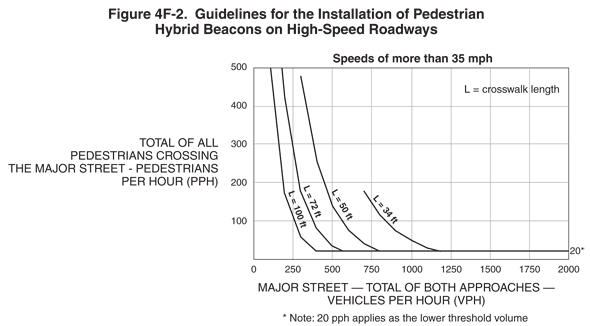
Figure 4F-2. Guidelines for the Installation of Pedestrian Hybrid Beacons on High-Speed Roadways
This figure shows a graph depicting guidelines for the installation of pedestrian hybrid beacons on high-speed roadways at speeds of more than 35 mph. The figure displays four curves for different crosswalk lengths: 34 ft, 50 ft, 72 ft, and 100 ft.
The table below shows the approximate vehicles per hour (VPH) on the major street and corresponding pedestrians per hour (PPH) for the total of all pedestrians crossing the major street.
| Crosswalk length = 34 ft | Crosswalk length = 50 ft | Crosswalk length = 72 ft | Crosswalk length = 100 ft | ||||
|---|---|---|---|---|---|---|---|
| VPH on the major street (Total of both approaches) | PPH for total of all pedestrians crossing the major street | VPH on the major street (Total of both approaches) | PPH for total of all pedestrians crossing the major street | VPH on the major street (Total of both approaches) | PPH for total of all pedestrians crossing the major street | VPH on the major street (Total of both approaches) | PPH for total of all pedestrians crossing the major street |
| 2000 | 20* | 2000 | 20* | 2000 | 20* | 2000 | 20* |
| 1750 | 20* | 1750 | 20* | 1750 | 20* | 1750 | 20* |
| 1500 | 20* | 1500 | 20* | 1500 | 20* | 1500 | 20* |
| 1250 | 20* | 1250 | 20* | 1250 | 20* | 1250 | 20* |
| 1000 | 50 | 1000 | 20* | 1000 | 20* | 1000 | 20* |
| 750 | 150 | 750 | 25 | 750 | 20* | 750 | 20* |
| 500 | — | 500 | 150 | 500 | 25 | 500 | 20* |
| 250 | — | 250 | — | 250 | 300 | 250 | 100 |
| 225 | — | 225 | — | 175 | 500 | 100 | 500 |
* Note: 20 pph applies as the lower threshold volume.