
2009 Edition Part 6 Figure 6H-16. Surveying Along the Center Line of a Road with Low Traffic Volumes (TA-16)
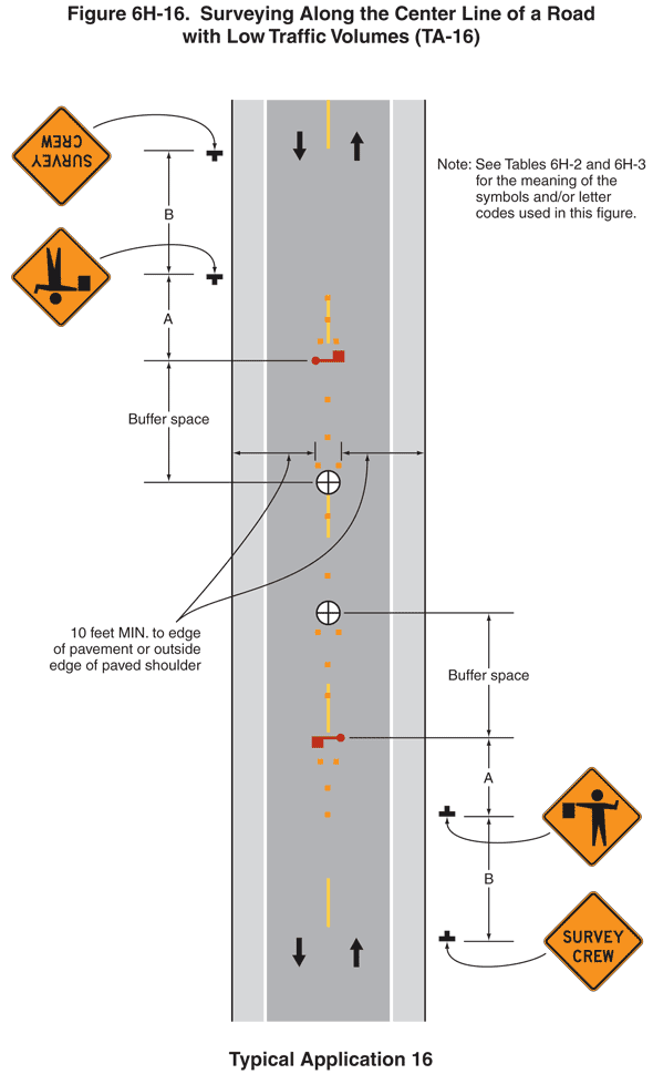
Figure 6H-16. Surveying Along the Center Line of a Road with Low Traffic Volumes (TA-16)
This figure illustrates surveying along the center line of a road with low traffic volumes. A legend under the figure states that this is Typical Application 16. A note states "See Tables 6H-2 and 6H-3 for the meaning of the symbols and/or letter codes used in this figure."
This figure shows a vertical two-lane roadway with one lane of traffic in each direction. A downward-pointing black arrow in the left lane and an upward-pointing arrow in the right lane denote the direction of travel. The opposing lanes are shown separated by a broken yellow line. A shoulder is shown to the right of each travel lane. The shoulders are shown separated from the travel lanes by a solid white line.
At the bottom of the figure and to the right of the northbound shoulder, a black inverted "T" is shown denoting a sign. The sign is shown as a diamond-shaped orange sign with a black border and the words "SURVEY CREW" in black. This sign is shown at a dimensioned distance B in advance of a second diamond-shaped orange sign with a black border to the right of the shoulder. This sign shows a black symbol of a flagger. This sign is shown at a dimensioned distance A in advance of a horizontal red symbol for a flagger shown on the broken yellow line facing northbound traffic. Directly in front of the flagger symbol along the broken yellow line, four orange squares are shown, denoting channelizing devices. The devices are shown beginning opposite the Flagger sign and forming a "V." The flagger symbol is shown at the beginning of an undimensioned buffer space in advance of a symbol for a surveyor, a black "x" on a white disc. The surveyor symbol is shown on the broken yellow line and is shown directly preceded by another "V" of four channelizing devices.
At the top of the figure and to the right of the southbound shoulder, the same series of two warning signs, a flagger symbol, and a second surveyor symbol is shown. The surveyor symbol is shown on the broken yellow line and is shown directly preceded by another "V" of four channelizing devices. The width of the "V" at its widest point is shown at a dimensioned distance in both travel lanes from the outside of the V to the edge of the travel lane with a label of "10 feet MIN. to edge of pavement or outside edge of paved shoulder." Two channelizing devices are shown on the broken yellow line between the two surveyor symbols.