MUTCD Proposed Revision No.
2 Change List
Introductory Notes to the User:
1. The pages referenced in the change list refer to the 2000 MUTCD Incorporating: Revision No. 1 dated December 28, 2001, Errata No. 1 dated June 14, 2001.
2. The Table of Contents at the beginning of the MUTCD has been changed to list only the Parts and Chapters, but not Sections, Figures, and Tables, and to remove page numbers from this list. The Table of Contents appearing at the beginning of each Part of the MUTCD have been changed to reflect changes in Section, Table, and Figure numbers and titles as well as the changes in page numbers .
Cover and
Introduction
1. Cover: For Cover and Cover of Introduction, change: “Incorporating: Revision No. 1 dated December 28, 2001, Errata No.1 dated June 14, 2001” to: “ Incorporating: Proposed Revision No. 2, Revision No. 1 dated December 28, 2001, Errata No. 1 dated June 14, 2001.”
2. Page i, Addresses for Publications Referenced in the MUTCD. In the address for American Association of State Highway and Transportation Officials, change the suite number from: “225” to: “249”; following American Railway Engineering and Maintenance-of-Way Association, insert: “Federal Highway Administration Report Center, Facsimile Number: 301.577.1421”; following Institute of Transportation Engineers, insert: “International Organization for Standards, c/o Mr. Gerard Kuso, Austrian Standards Institute, Heinestrabe 38, Postfach 130, A-1021, Wien, Austria” and “ISEA – The Safety Equipment Association, 1901 N. Moore St., Suite 808, Arlington, VA 22209”; following National Committee on Uniform Traffic Laws and Ordinances, insert “Occupational Safety and Health Administration, U.S. Department of Labor, 200 Constitution Ave., NW, Washington, DC 20210”; following Transportation Research Board, insert: “U.S. Architectural and Transportation Barriers Compliance Board (The U.S. Access Board), 1131 F Street, NW, Suite 1000, Washington, DC, 20004-1111”.
3. Page I-1, Introduction. Under Standard, change: “Traffic control devices contained in this Manual shall not be protected by a patent or copyright, except for the Interstate Shield.” to: “Traffic control devices contained in this Manual shall not be protected by a patent, trademark, or copyright, except for the Interstate Shield and any other items owned by FHWA.”
4. Page I-2, Table I-1, Evolution of the MUTCD. In Row 11 (opposite Year “2000”), Column 3 (headed “”Month/Year Revised”), change: “6/01” to: “12/01”.
5. Page I-3. Under Support, first paragraph, remove the last sentence: “Section 15-104 of the UVC adopts the MUTCD as the standard for conformance.”; under Standard, in listed item number 2, in the second sentence, change: “All Guidance statements are labeled and the text appears in large type.” to: “All Guidance statements are labeled, and the text appears in large type.”
6. Page I-4. At the end of the Introduction, after Guidance, add a new second Support and an additional Standard:
Support:
The
following information will be useful when reference is being made to a specific
portion of text in this Manual.
There are ten
Parts in this Manual and each part is comprised of one or more Chapters. Each
Chapter is comprised of one or more sections. Parts are given a numerical
identification, such as Part 2-Signs. Chapters are identified by the Part
number and a letter, such as Chapter 2B-Regulatory Signs. Sections are
identified by the Chapter number and letter followed by a decimal point and a
number, such as Section 2B.03-Size of Regulatory Signs.
Each Section is comprised of one or more paragraphs. The paragraphs are indented but are not identified by a number or letter. Paragraphs are counted from the beginning of each Section without regard to the intervening text headings (Standard, Guidance, Option, or Support). Some paragraphs have lettered or numbered items. As an example of how to cite this Manual, the phrase “Not less than 12 m (40 ft) beyond the stop line” that appears on page 4D-24 of this Manual would be referenced in writing as “Section 4D.15, P7, D1(a),” and would be verbally referenced as “Item D1(a) of Paragraph 7 of Section 4D.15.
Standard:
In accordance with 23 C.F.R. 655.603(b)(1), States or
other Federal agencies shall adopt changes to the MUTCD within 2 years of
issuance. For new devices or
replacement of damaged devices, compliance shall be required effective
immediately upon adoption by the State or other Federal agency. For devices in good condition, the following
list of special compliance dates shall apply.
Section 2B.03 Size of Regulatory Signs---increased sign sizes and other changes to Table 2B-1---proposed 10 years from effective date of Final Rule.
Section 2B.04 STOP Sign (R1-1)---4-WAY plaque requirement---January 17, 2004.
Section 2B.16 Removal of R2-5 Series Reduced Speed Ahead signs and use of W3-5 or W3-5a warning signs instead---proposed 10 years from effective date of Final Rule.
Section 2B.23 Reversible Lane Control Signs (R3-9d, R3-9f through R3-9i)---removal of R3-9c and R3-9e signs---proposed 10 years from effective date of Final Rule.
Section 2B.32 ONE WAY Signs (R6-1, R6-2)---placement requirement at intersecting alleys---January 17, 2008.
Section 2B.46
Hazardous Material Signs (R14-2, R14-3)---change in sign
legend---proposed 5 years from effective date of Final Rule.
Section 2B.49 High-Occupancy Vehicle (HOV) Lanes---new section in Millennium Edition---January 17, 2007.
Section 2B.50 High-Occupancy Vehicle Sign Applications and Placement---new section in Millennium Edition---January 17, 2007.
Section 2B.51
Photo Enforced Signs (R10-18, R10-19)---new section---proposed 10 years
from effective date of Final Rule.
Section 2B.52 Yield Here to Pedestrians Signs (R1-5, R1-5a)---new section---proposed 10 years from effective date of Final Rule.
Section 2C.04 Size of Warning Signs---increased sizes of W4-1, W5-2, W6-3, and W12-1 signs---January 17, 2008.
Section 2C.04 Size of Warning Signs---sizes of W1 Series Arrows signs, W7 Series truck runaway signs, W12-2P low clearance signs, and W10-1 advance grade crossing sign---proposed 10 years from effective date of Final Rule.
Section 2C.23 PAVEMENT ENDS Sign (W8-3)---removal of symbol sign---January 17, 2011.
Section 2C.24 Shoulder and UNEVEN LANES Signs (W8-4, W8-9, W8-9a, and W8-11)---removal of symbol signs---January 17, 2011.
Section 2C.28 Merge Signs (W4-1, W4-1a)---Entering Roadway Merge sign (W4-1a)---proposed 10 years from effective date of Final Rule.
Section 2C.29 Added Lane Signs (W4-3, W4-3a)---Entering Roadway Added Lane sign (W4-3a)---proposed 10 years from effective date of Final Rule.
Section 2C.30 Lane Ends Signs (W4-2, W9-1), W9-2)---new design of W4-2 sign---proposed 10 years from effective date of Final Rule.
Section 2C.34 Intersection Warning Signs (W2-1 through W2-6)---new design of Circular Intersection (W2-6) sign---proposed 10 years from effective date of Final Rule.
Section 2C.37 Nonvehicular Signs (W11-1, W11-2, W11-3, W11-4, W11-11, W11-14, W11-14a, W11-15)---elimination of crosswalk lines from Crossing signs and use of diagonal downward pointing arrow supplemental plaque (W16-7) if at the crossing---January 17, 2011.
Section 2C.37 Nonvehicular Signs (W11-1, W11-2, W11-3, W11-4, W11-11, W11-14, W11-14a, W11-15)---W11-1, W11-14, W11-14a, and W11-5 signs---proposed 10 years from effective date of Final Rule.
Section 2C.49
PHOTO ENFORCED Plaque (W16-10)---new section---proposed 10 years from
effective date of Final Rule.
Section 2C.51 Speed Reduction Signs (W3-5, W3-5a)---new section---proposed 10 years from effective date of Final Rule.
Section 2C.54 Truck Rollover Warning Signs (W1-13, W1-13a)---new section---proposed 10 years from effective date of Final Rule.
Section 2D.38
Street Name Sign (D3-1)---letter and symbol sizes, all other
provisions---January 9, 2012.
Section 2D.39 Advance Street Name Signs (D3-2)---new section---January 9, 2012.
Section 2D.45 General Service Signs (D9 Series)---Traveler Info Call 511 (D12-5) sign, Channel 9 Monitored (D12-3) sign---proposed 10 years from effective date of Final Rule.
Section 2D.46 Reference Location Signs (D10-1 through D10-3)---location and spacing of Reference Location signs, design of enhanced location reference sign (D10-7) and intermediate enhanced location reference sign (D10-8)---proposed 10 years from effective date of Final Rule.
Section 2E.28 Interchange Exit Numbering---size of exit number plaque---January 17, 2008.
Section 2E.28 Interchange Exit Numbering---LEFT on exit number plaques for left exits---proposed 15 years from effective date of Final Rule.
Section 2E.30
Advance Guide Signs---advance placement distance---January 17, 2008.
Section 2F.05 Size of Lettering---minimum height of letters and numerals on specific service signs--- January 17, 2011.
Section 2I.03 EVACUATION ROUTE Sign (EM-1)---new design and size of EM-1 sign---proposed 10 years from effective date of Final Rule.
Section 3B.01 Yellow Centerline Pavement Markings and Warrants---new section in Millennium Edition---January 3, 2003.
Section 3B.07 Warrants for Use of Edge Lines---new section in Millennium Edition---January 3, 2003.
Section 3B.14 Raised Pavement Markers Substituting for Pavement Markings---spacing requirements---proposed 10 years from effective date of Final Rule.
Section 3C.01 Object Marker Design and Placement Height---width of stripes on Type 3 striped marker---proposed 10 years from effective date of Final Rule.
Section 4D.01
General---location of signalized midblock crosswalks---proposed 10 years
from effective date of Final Rule.
Section 4D.05 Application of Steady Signal Indications---item B.4 in STANDARD---proposed 5 years from effective date of Final Rule.
Section 4D.12 Flashing Operation of Traffic Control Signals---duration of steady red clearance interval in change from red-red flashing mode to steady (stop-and-go) mode---proposed 5 years from effective date of Final Rule.
Section 4E.04 Size, Design, and Illumination of Pedestrian Signal Head Indications---removal of outline-style symbolic pedestrian signal indications---proposed 10 years from effective date of Final Rule.
Section 4E.06 Accessible Pedestrian Signals---new section in Millennium Edition---January 17, 2005.
Section 4E.07 Countdown Pedestrian Signals---new section---proposed 10 years from effective date of Final Rule.
Section 4E.09 Accessible Pedestrian Signal Detectors---new section in Millennium Edition---January 17, 2005.
Section 4E.10 Pedestrian Intervals and Signal Phases---pedestrian clearance time sufficient to travel to far side of the traveled way---proposed 5 years from effective date of Final Rule.
Section 4F.04 Emergency Beacon---new section---proposed 10 years from effective date of Final Rule.
Section 4L.03
In-Roadway Lights at Highway-Rail Grade Crossings and Highway-Light Rail
Transit Grade Crossings---new section---proposed 10 years from effective date
of Final Rule.
Section 6D.01 Pedestrian Considerations---all new provisions for pedestrian accessibility---proposed 5 years from effective date of Final Rule.
Section 6D.02 Worker Considerations---high-visibility apparel requirements---proposed 5 years from effective date of Final Rule.
Section 6E.02 High-Visibility Clothing---high-visibility apparel requirements for flaggers---proposed 5 years from effective date of Final Rule.
Section 6F.55 Channelizing Devices---requirements for detectability by users of long canes---proposed 5 years from effective date of Final Rule.
Section 6F.56 Cones---width of retroreflective stripes---proposed 5 years from effective date of Final Rule.
Section 6F.60 Type
I, II, or III Barricades---provisions for pedestrian accessibility---proposed 5
years from effective date of Final Rule.
Section 6F.63 Temporary Raised Islands---requirements for pedestrian accessibility---proposed 5 years from effective date of Final Rule.
Section 7B.08 School Advance Warning Sign (S1-1)--- elimination of crosswalk lines from Crossing signs and use of diagonal downward pointing arrow supplemental plaque (W16-7) if at the crossing---January 17, 2011.
Section 7E.04 Uniform of Adult Guards and Student Patrols---requirement for high-visibility apparel for adult guards---proposed 5 years from effective date of Final Rule
Section 8B.02 Highway-Rail Grade Crossing (Crossbuck) Signs (R15-1, R15-2, R15-9)---retroreflective strip on crossbuck support---January 17, 2011.
Section 8B.02 Highway-Rail Grade Crossing (Crossbuck) Signs (R15-1, R15-2, R15-9)---Crossbuck Shield sign (R15-9)---proposed 10 years from effective date of Final Rule.
Section 8B.03 Highway-Rail Grade Crossing Advance Warning Signs (W10 Series)--- removal of existing W10-6 series signs---January 17, 2006.
Section 8D.07 Traffic Control Signals at or Near Highway-Rail Grade Crossings---pre-signals---proposed 10 years from effective date of Final Rule.
Section 9B.04 Bicycle Lane Signs (R3-17, R3-17a, R3-17b)---deletion of preferential lane symbol (diamond) for bicycle lane signs---January 17, 2006.
Section 9B.17 Bicycle Crossing Warning Sign (W11-1)--- elimination of crosswalk lines from Crossing signs and use of diagonal downward pointing arrow supplemental plaque (W16-7) if at the crossing---January 17, 2011.
Chapter 9C Markings---deletion of preferential lane symbol (diamond) for bicycle pavement markings---January 17, 2007.
Part 10 Traffic Controls for Highway-Light Rail Transit Grade Crossings---automatic gates, flashing-light signals, and blank-out signs---January 17, 2006.
Section 10C.15
Highway-Light Rail Transit Grade Crossing Advance Warning Signs (W10
Series)---removal of existing W10-6 series signs---January 17, 2006.
Part 1
1. Cover. Change: “Incorporating: Revision No. 1 dated December 28, 2001, Errata No.1 dated June 14, 2001” to: “ Incorporating: Proposed Revision No. 2, Revision No. 1 dated December 28, 2001, Errata No. 1 dated June 14, 2001.”
2. Page 1A-4, Section 1A.05, Maintenance of Traffic Control Devices. Under Guidance, change: “Physical maintenance of traffic control devices should be performed to ensure that legibility is retained, that the device is visible, and that it functions properly in relation to other traffic control devices in the vicinity.” to: “Physical maintenance of traffic control devices should be performed to ensure that legibility is retained, that the device is visible, and that the device functions properly in relation to other traffic control devices in the vicinity.”; and remove the last two paragraphs of the Guidance in their entirety.
3. Page 1A-7, Section 1A.10, Interpretations, Experimentations, and Changes. Change the first Guidance to a Standard, and change: “Requests for any interpretation, permission to experiment, or change should be sent...” to: “Requests for any interpretation, permission to experiment, interim approval, or change shall be sent...”; under second Guidance, change Item B from “...the need for a revised interpretation” to: ...the need for an interpretation”; under third Support, change: “Requests to experiment include consideration of testing or evaluating a new traffic control device,...” to: “Requests to experiment include consideration of field deployment for the purpose of testing or evaluating a new traffic control device,…”
4.
Page
1A-8, Figure 1A-1,, Typical Process for Requesting and Conducting
Experimentations for New Traffic Control Devices. In the Figure title, change: “Typical” to: “Example of.”
5. Page 1A-9, Section 1A.10, Interpretations, Experimentations, and Changes. Under Guidance, in listed item E, change: “A legally binding statement certifying that the traffic control device is not protected by a patent or copyright.” to: “A legally binding statement certifying that the concept of the traffic control device is not protected by a patent or copyright.”
6. Page 1A-10, Section 1A.10, Interpretations, Experimentations, and Changes. Under Guidance after Item C, insert:
Support:
Requests for interim approval include consideration of allowing interim use, pending official rulemaking, of a new traffic control device, a revision to the application or manner of use of an existing traffic control device, or a provision not specifically described in this Manual. If granted, interim approval will result in the traffic control device or application being placed into the next scheduled rulemaking process for revisions to this Manual. The device or application will be permitted to remain in place, under any conditions established in the interim approval, until an official rulemaking action has occurred.
Interim approval is considered based on the results of successful experimentation, results of analytical or laboratory studies, and/or review of non-U.S. experience with a traffic control device or application. Interim approval considerations include an assessment of relative risks, benefits, and costs. Interim approval includes conditions that jurisdictions agree to comply with in order to use the traffic control device or application until an official rulemaking action has occurred.
Standard:
A request for interim approval will be considered only when submitted by the public agency or private toll facility responsible for the operations of the road or street on which the use of a device or application under interim approval is to take place.
Guidance:
The request for permission to place a traffic control device under interim approval should contain the following:
A. A statement indicating the nature of the problem.
B. A description of the proposed change to the traffic control device or application of the traffic control device, how it was developed, the manner in which it deviates from the standard, and how it is expected to be an improvement over existing standards.
C. The location(s) where it will be used and any illustration that would be helpful
to understand the traffic control device or use of the traffic control device.
D. A legally-binding statement certifying that the concept of the traffic control
device is not protected by a patent or copyright.
E. A detailed completed research or evaluation on this traffic control device.
F. An agreement to restore the site(s) of the interim approval to a condition
that complies with the provisions of the Manual within 3 months following
the issuance of a final rule on this traffic control device. This agreement
must also provide that the agency sponsoring the interim approval will
terminate use of the device or application installed under the interim approval
at any time that it determines significant safety concerns are directly or
indirectly attributable to the device or application. The FHWA’s Office of
Transportation Operations has the right to terminate the interim approval at
any time if there is an indication of safety concerns.
Option:
A state may submit a request for interim approval for all jurisdictions in that State, as long as the request contains the information listed in the Guidance above.
Standard:
Once an interim approval is granted to any jurisdiction for a particular traffic control device or application, subsequent jurisdictions shall be granted interim approval for that device or application by submitting a letter to the FHWA Office of Transportation Operations indicating they will abide by item F above and the specific conditions contained in the original interim approval.
A local jurisdiction using a traffic control device or application under an interim approval that was granted either directly to that jurisdiction or on a statewide basis based on the State’s request shall inform the State of the locations of such use.
7. Page 1A-10, Section 1A.11, Relation to Other Documents. Under Standard, change:
“Standard Alphabets for Highway Signs and Pavement Markings,”1977 Edition (FHWA); “Standard Alphabets for Highway Signs,” 1966 Edition (FHWA); “Standard Color Tolerance Limits,” (FHWA); and “Standard Highway Signs,” 1979 Edition (FHWA).”
to:
“Standard Alphabets for Highway Signs and Pavement Markings,” 2002 Edition (FHWA); “Standard Alphabets for Highway Signs,” 2002 Edition (FHWA); “Color Specifications for Retroreflective Sign and Pavement Marking Materials,” (FHWA); and “Standard Highway Signs,” 2002 Edition (FHWA)”;
under Support, change:
A. “Vehicle Traffic Control Signal Heads,” Part 1 – 1985 Edition; Part 2 – 1998 Edition (Institute of Transportation Engineers – (ITE)
B. “Pedestrian Traffic Control Signal Indications,” 1985 Edition (ITE)
C. “Purchase Specification for Flashing and Steady Burn Warning Lights,” 1981 Edition (ITE)
D. “Traffic Signal Lamps,” 1980 Edition (ITE)
to:
1. “A Policy on Geometric Design of Highways and Streets,” 2001 Edition (American Association of State Highway and Transportation Officials – AASHTO)
2. “Guide for the Development of Bicycle Facilities,” 1999 Edition (AASHTO)
3. “Guide to Metric Conversion,” 1993 Edition (AASHTO)
4. “Guidelines for the Selection of Supplemental Guide Signs for Traffic Generators Adjacent to Freeways,” 1993 Edition (AASHTO)”
8.
Page 1A-11, Figure 1A-2, Typical Process for
Incorporating New Traffic Control Devices Into the MUTCD. In the Figure title, change title from:
“Typical” to: “Example of”; Replace the flowchart with a new flowchart,
laid out as follows:
1st row is comprised of 3 action boxes: “Experiment Successful (see Figure 1A-1)”; “Analytical or Laboratory Study Results and/or non-U.S. experimentation”; and “Request for change from jurisdiction or interested party.”
Boxes in 1st row all flow to single action box in 2nd row: “FHWA Review.”
2nd row box flows to question diamond in 3rd row: “Accepted for Federal rulemaking?” The NO response flows to a second question diamond in 3rd row: “Further experimentation required?” The NO response flows to action box: “Jurisdiction restores experiment site to original condition.” The YES response flows to action box: “See Figure 1A-1.”
The YES response to 3rd row “Accepted for Federal rulemaking?” splits flow into two tiers, beginning the 4th row and flowing parallel to each other.
Tier 1 flows to a question diamond: “Interim approval?” The NO response flows to an action box: “FHWA notifies interested parties (if any).” The YES response flows to a series of action boxes, in order: “FHWA notifies all States and distributes simplified application form for submission by jurisdictions”; “Jurisdictions apply for and receive Interim Approval”; “Jurisdictions deploy devices under Interim Approval conditions.”
Tier 2 flows to a series of action boxes, in order: “FHWA prepares Notice of Proposed Amendment”; FHWA publishes Notice of Proposed Amendment in Federal Register”; “Docket comment period”; “FHWA reviews comments”; “FHWA prepares Final Rule”; “FHWA publishes Final Rule.”
The flow of Tier 2 then splits: One direction flows to a final action box: “States adopt changes within 2 years, unless otherwise noted in Final Rule.”
Second flow direction meets the end of the flow of Tier 1, and flows to a question diamond: “Final Rule different from Interim Approval?” The NO response flows to a final action box: “No action required.” The YES response flows to a final action box: “Jurisdictions restore sites of Interim Approval to previous condition and/or comply with Final Rule.”
9. Page 1A-12, Section 1A.11, Relation to Other Documents. Under Support, change:
E. “Uniform Vehicle Code (UVC) and Model Traffic Ordinance,” 1992 Edition (National Committee on Uniform Traffic Laws and Ordinances)
F. “Traffic Engineering Handbook,” 1999 Edition (ITE)
G. “Highway Capacity Manual,” 1998 Edition (Transportation Research Board – TRB)
H. “A Policy on Geometric Design of Highway and Streets,” 1994 Edition (American Association of State Highway and Transportation Officials – AASHTO)
I. “Guidelines for the Selection of Supplemental Guide Signs for Traffic Generators Adjacent to Freeways,” 1993 Edition (AASHTO)
J. “List of Control Cities for Use in Guide Signs on Interstate Highways,” 1993 Edition (AASHTO)
K. “Manual of Transportation Engineering Studies,” 1994 Edition (ITE)
L. “Roadside Design Guide,” 1996 Edition (AASHTO)
M. “School Trip Safety Program Guidelines,” 1984 Edition (ITE)
N. “Manual of Traffic Signal Design,” 1991 Edition (ITE)
O. “Traffic Detector Handbook,” 1991 Edition (ITE)
P. “2000 AREMA Communications & Signals Manual,” American Railway Engineering & Maintenance-of-Way Association (AREMA)
Q. “Preemption of Traffic Signals at or Near Railroad Grade Crossings with Active Warning Devices,” (ITE)
R. “Highway-Rail Intersection Architecture,” U.S. Department of Transportation, Federal Railroad Administration (USDOT/FRA)
S. “Practice for Roadway Lighting,” RP-8, 1983, Illuminating Engineering Society (IES)
T.
“Safety Guide for the Prevention of Radio Frequency
Radiation Hazards in the Use of Commercial Electric Detonators (Blasting
Caps),” Safety Library Publication No. 20, Institute of Makers of Explosives
U.
“Accessible Pedestrian Signals,” A-37, U.S. Architectural
and Transportation Barriers Compliance Board (The U. S. Access Board)
to:
5. “List of Control Cities for Use in Guide Signs on Interstate Highways,” 1993 Edition (AASHTO)
6. “Roadside Design Guide,” 1996 Edition (AASHTO)
7. “Standard Specifications for Movable Highway Bridges,” 1988 Edition (AASHTO)
8. “Traffic Engineering Metric Conversion Folders – Addendum to the Guide to Metric Conversion,” 1993 Edition (AASHTO)
9. “2000 AREMA Communications & Signals Manual,” American Railway Engineering & Maintenance-of-Way Association (AREMA)
10. “Designing Sidewalks and Trails for Access – Part 2 – Best Practices Design Guide,” 2001 Edition (FHWA) [Publication No. FHWA – EP – 01 – 027]
11. “Practice for Roadway Lighting,” RP-8, 1983, Illuminating Engineering Society (IES)
12. “Safety Guide for the Prevention of Radio Frequency Radiation Hazards in the Use of Commercial Electric Detonators (Blasting Caps),” Safety Library Publication No. 20, Institute of Makers of Explosives
13. “American National Standard for High-Visibility Safety Apparel,” (ANSI/ISEA 107-1999), 1999 Edition, ISEA – The Safety Equipment Association
14. “Manual of Traffic Signal Design,” 1991 Edition (Institute of Transportation Engineers - ITE)
15. “Manual of Transportation Engineering Studies,” 1994 Edition (ITE)
16. “Pedestrian Traffic Control Signal Indications,” 1985 Edition (ITE)
17. “Preemption of Traffic Signals at or Near Railroad Grade Crossings with Active Warning Devices,” (ITE)
18. “Purchase Specification for Flashing and Steady Burn Warning Lights,” 1981 Edition (ITE)
19. “School Trip Safety Program Guidelines,” 1984 Edition (ITE)
20. “Traffic Detector Handbook,” 1991 Edition (ITE)
21. “Traffic Engineering Handbook,” 1999 Edition (ITE)
22. “Traffic Signal Lamps,” 1980 Edition (ITE)
23. “Traffic Control Devices Handbook,” 2001 Edition (ITE)
24. “Vehicle Traffic Control Signal Heads,” Part 1 – 1985 Edition; Part 2 - 1998 Edition (ITE)
25. “Uniform Vehicle Code (UVC) and Model Traffic Ordinance,” 1992 Edition (National Committee on Uniform Traffic Laws and Ordinances)
26. “Occupational Safety and Health Administration Regulations (Standards – 29 CFR), General Safety and Health Provisions – 1926.20” amended June 30, 1993, Occupational Safety and Health Administration (OSHA)
27. “Highway Capacity Manual,” 1998 Edition (Transportation Research Board – TRB)
28. “Recommended Procedures for The Safety Performance Evaluation of Highway Features,” (NCHRP Report 350), 1993 Edition (Transportation Research Board – TRB)
29. “Accessible Pedestrian Signals,” A-37, U.S. Architectural and Transportation Barriers Compliance Board (The U.S. Access Board)
30. “Building a True Community – Final Report – Public Rights-of-Way Access Advisory Committee (PRWAAC),” 2001 Edition (The U.S. Access Board)
31. “The Americans with Disabilities Act Accessibility Guidelines (ADAAG),” July 1998 Edition (The U.S. Access Board)
32. “Highway-Rail Intersection Architecture,” U.S. Department of Transportation, Federal Railroad Administration (USDOT/FRA)
10. Page 1A-12, Section 1A.12, Color Code. Under Support, change: “The following color code establishes general meanings for 9 colors of a total of 12 colors…” to: “The following color code establishes general meanings for 10 colors of a total of 12 colors…”
11. Page 1A-13, Section 1A.12, Color Code. Under Support, change: “The three colors for which general meanings…” to: “The two colors for which general meanings...” Under Standard, change:
A. Yellow – warning
B. Red – stop or prohibition
C. Blue – road user services guidance, tourist information, and evacuation route
D. Green – indicated movements permitted, direction guidance
E. Brown – recreational and cultural interest area guidance
F. Orange – temporary traffic control
G. Black – regulation
H. White – regulation
I. Fluorescent Yellow-Green – pedestrian warning, bicycle warning, school bus and school warning
J. Purple – unassigned
K. Light Blue – unassigned
L. Coral – unassigned
to:
A. Black – regulation
B. Blue – road user services guidance, tourist information, and evacuation route
C. Brown – recreational and cultural interest area guidance
D. Coral – incident management
E. Fluorescent Yellow-Green – pedestrian warning, bicycle warning, school bus and school warning
F. Green – indicated movements permitted, direction guidance
G. Light Blue – unassigned
H. Orange – temporary traffic control
I. Purple – unassigned
J. Red – stop or prohibition
K. White – regulation
L. Yellow – warning
12. Pages 1A-14 through 1A-22, Section 1A.13, Definitions of Words and Phrases in This Manual. Under Standard, change:
1. Active Grade Crossing Warning System – the flashing-light signals, with or without warning gates, together with the necessary control equipment used to inform road users of the approach or presence of trains at highway-rail grade crossings.
2. Approach – all lanes of traffic moving towards an intersection or a midblock location from one direction, including any adjacent parking lane(s).
3. Arterial Highway (Street) – a general term denoting a highway primarily used by through traffic, usually on a continuous route or a highway designated as part of an arterial system.
4. Average Day – a day representing traffic volumes normally and repeatedly found at a location, typically a weekday when volumes are influenced by employment or a weekend when volumes are influenced by entertainment or recreation.
5. Beacon -- a highway traffic signal with one or more signal sections that operates in a flashing mode.
6. Bicycle -- a pedal-powered vehicle upon which the human operator sits.
7. Bicycle Lane – a portion of a roadway that has been designated by signs and pavement markings for preferential or exclusive use by bicyclists.
8. Centerline Markings – the yellow pavement marking line(s) that delineates the separation of traffic lanes that have opposite directions of travel on a roadway. These markings need not be at the geometrical center of the pavement.
9. Changeable Message Signs – signs that are capable of displaying more than one message, changeable manually, by remote control, or by automatic control. These signs are referred to as Dynamic Message Signs in the National Intelligent Transportation Systems (ITS) Architecture.
10. Channelizing Line Marking – a wide or double solid white line used to form islands where traffic in the same direction of travel is permitted on both sides of the island.
11. Circular Intersection – an intersection that has an island, generally circular in design, located in the center of the intersection where traffic passes to the right of the island. Circular intersections include roundabouts, rotaries, and traffic circles.
12. Clear Zone – the total roadside border area, starting at the edge of the traveled way, that is wide enough to allow an errant driver to stop or regain control of a vehicle. This area might consist of a shoulder, a recoverable slope, and/or a nonrecoverable, traversable slope with a clear run-out area at its toe.
13. Concurrent Flow HOV Lane – an HOV lane that is operated in the same direction as the adjacent mixed flow lanes, separated from the adjacent general purpose freeway lanes by a standard lane stripe, painted buffer, or barrier.
14. Contraflow Lane – a lane operating in a direction opposite to the normal flow of traffic designated for peak direction of travel during at least a portion of the day. Contraflow lanes are usually separated from the off-peak direction lanes by plastic pylons, or by moveable or permanent barrier.
15. Conventional Road – a street or highway other than a low-volume road (as defined in Section 5A.01), expressway, or freeway.
16. Collector Highway – a term denoting a highway that in rural areas connects small towns and local highways to arterial highways, and in urban areas provides land access and traffic circulation within residential, commercial and business areas and connects local highways to the arterial highways.
17. Crosswalk – (a) that part of a roadway at an intersection included within the connections of the lateral lines of the sidewalks on opposite sides of the highway measured from the curbs or in the absence of curbs, from the edges of the traversable roadway, and in the absence of a sidewalk on one side of the roadway, the part of a roadway included within the extension of the lateral lines of the sidewalk at right angles to the centerline; (b) any portion of a roadway at an intersection or elsewhere distinctly indicated for pedestrian crossing by lines or other markings on the surface.
18. Crosswalk Lines – white pavement marking lines that identify a crosswalk.
19. Delineators – retroreflective devices mounted on the roadway surface or at the side of the roadway in a series to indicate the alignment of the roadway, especially at night or in adverse weather.
20. Dynamic Envelope – the clearance required for the train and its cargo overhang due to any combination of loading, lateral motion, or suspension failure.
21. Edge Line Markings – white or yellow pavement marking lines that delineate the right or left edge(s) of a traveled way.
22. End-of-Roadway Marker – a device used to warn and alert road users of the end of a roadway in other than temporary traffic control zones.
23. Engineering Judgment – the evaluation of available pertinent information, and the application of appropriate principles, Standards, Guidance, and practices as contained in this Manual and other sources, for the purpose of deciding upon the applicability, design, operation, or installation of a traffic control device. Engineering judgment shall be exercised by an engineer, or by an individual working under the supervision of an engineer, through the application of procedures and criteria established by the engineer. Documentation of engineering judgment is not required.
24. Engineering Study – the comprehensive analysis and evaluation of available pertinent information, and the application of appropriate principles, Standards, Guidance, and practices as contained in this Manual and other sources, for the purpose of deciding upon the applicability, design, operation, or installation of a traffic control device. An engineering study shall be performed by an engineer, or by an individual working under the supervision of an engineer, through the application of procedures and criteria established by the engineer. An engineering study shall be documented.
25. Expressway – a divided highway with partial control of access.
26. Flashing (Flashing Mode) – a mode of operation in which a traffic signal indication is turned on and off repetitively.
27. Freeway – a divided highway with full control of access.
28. Guide Sign – a sign that shows route designations, destinations, directions, distances, services, points of interest, or other geographical, recreational, or cultural information.
29. High Occupancy Vehicle (HOV) – a motor vehicle carrying at least two or more persons, including carpools, vanpools, and buses.
30. Highway – a general term for denoting a public way for purposes of travel by vehicular travel, including the entire area within the right-of-way.
31. Highway-Rail Grade Crossing – the general area where a highway and a railroad’s right-of-way cross at the same level, within which are included the railroad tracks, highway, and traffic control devices for highway traffic traversing that area.
32. Highway Traffic Signal – a power-operated traffic control device by which traffic is warned or directed to take some specific action. These devices do not include power-operated signs, illuminated pavement markers, barricade warning lights, or steady burning electric lamps.
33. HOV Lane – any preferential lane designated for exclusive use by high-occupancy vehicles for all or part of a day – including a designated lane on a freeway, other highway, street, or independent roadway on a separate right-of-way.
34. Interchange – a system of interconnecting roadways providing for traffic movement between two or more highways that do not intersect at grade.
35. Intermediate Interchange – an interchange with an urban or rural route that is not a major or minor interchange as defined herein.
36. Intersection – (a) the area embraced within the prolongation or connection of the lateral curb lines, or if none, the lateral boundary lines of the roadways of two highways that join one another at, or approximately at, right angles, or the area within which vehicles traveling on different highways that join at any other angle may come into conflict; (b) the junction of an alley or driveway with a roadway or highway shall not constitute an intersection.
37. Island – a defined area between traffic lanes for control of vehicular movements or for pedestrian refuge. It includes all end protection and approach treatments. Within an intersection area, a median or an outer separation is considered to be an island.
38. Lane Line Markings – white pavement marking lines that delineate the separation of traffic lanes that have the same direction of travel on a roadway.
39. Lane-Use Control Signal – a signal face displaying indications to permit or prohibit the use of specific lanes of a roadway or to indicate the impending prohibition of such use.
40. Legend – see Sign Legend.
41. Logo – a distinctive emblem, symbol, or trademark that identifies a product or service.
42. Longitudinal Markings – pavement markings that are generally placed parallel and adjacent to the flow of traffic such as lane lines, centerlines, edge lines, channelizing lines, and others.
43. Major Interchange – an interchange with another freeway or expressway, or an interchange with a high-volume multilane highway, principal urban arterial, or major rural route where the interchanging traffic is heavy or includes many road users unfamiliar with the area.
44. Major Street – the street normally carrying the higher volume of vehicular traffic.
45. Median – the area between two roadways of a divided highway measured from edge of traveled way to edge of traveled way. The median excludes turn lanes. The median width might be different between intersections, interchanges, and at opposite approaches of the same intersection.
46. Minor Interchange – an interchange where traffic is local and very light, such as interchanges with land service access roads. Where the sum of the exit volumes is estimated to be lower than 100 vehicles per day in the design year, the interchange is classified as local.
47. Minor Street – the street normally carrying the lower volume of vehicular traffic.
48. Object Markers - devices used to mark obstructions within or adjacent to the roadway.
49. Occupancy Requirement – any restriction that regulates the use of a facility for any period of the day based on a specified number of persons in a vehicle.
50. Occupants – the people driving or riding in a car, truck, bus, or other vehicle.
51. Paved – a bituminous surface treatment, mixed bituminous concrete, or Portland cement concrete roadway surface that has both a structural (weight bearing) and a sealing purpose for the roadway.
52. Pedestrian – a person afoot, in a wheelchair, on skates, or on a skateboard.
53. Platoon – a group of vehicles or pedestrians traveling together as a group, either voluntarily or involuntarily, because of traffic signal controls, geometrics, or other factors.
54. Preferential Lane Marking – white lines formed in a diamond shape.
55. Principal Legend – place names, street names, and route numbers placed on guide signs.
56. Public Road – any road or street under the jurisdiction of and maintained by a public agency and open to public travel.
57. Raised Pavement Marker – a device with a height of at least 10 mm (0.4 in) mounted on or in a road surface and intended to supplement or substitute for pavement markings.
58. Regulatory Signs – a sign that gives notice to road users of traffic laws or regulations.
59. Retroreflectivity – a property of a surface that allows a large portion of the light coming from a point source to be returned directly back to a point near its origin.
60. Right-of-Way [Assignment] – the permitting of vehicles and/or pedestrians to proceed in a lawful manner in preference to other vehicles or pedestrians by the display of sign or signal indications.
61. Road – see Roadway.
62. Roadway – that portion of a highway improved, designed, or ordinarily used for vehicular travel and parking lanes, but exclusive of the sidewalk, berm, or shoulder even though such sidewalk, berm, or shoulder is used by persons riding bicycles or other human-powered vehicles. In the event a highway includes two or more separate roadways, the term roadway as used herein shall refer to any such roadway separately, but not to all such roadways collectively.
63. Roadway Network – a geographical arrangement of intersecting roadways.
64. Road User – a vehicle operator, bicyclist, or pedestrian within the highway, including workers in temporary traffic control zones.
65. Rumble Strip – a series of intermittent, narrow, transverse areas of rough-textured, slightly raised, or depressed road surface that is installed to alert road users to unusual traffic conditions.
66. Rural Highway – a type of roadway normally characterized by lower volumes, higher speeds, fewer turning conflicts, and less conflict with pedestrians.
67. Shared Roadway – a roadway that is officially designated and marked as a bicycle route, but which is open to motor vehicle travel and upon which no bicycle lane is designated.
68. Shared-Use Path – a bikeway physically separated from motorized vehicular traffic by an open space or barrier and either within the highway right-of-way or within an independent alignment. Shared-used paths might also be used by pedestrians, skaters, wheelchair users, joggers, and other nonmotorized users.
69. Sidewalk – that portion of a street between the curb line, or the lateral line of a roadway, and the adjacent property line or on easements of private property, intended for use by pedestrians.
70. Sign – any traffic control device that is intended to communicate specific information to road users through a word or symbol legend. Signs do not include traffic control signals, pavement markings, delineators, or channelization devices.
71. Sign Assembly – a group of signs, located on the same support(s), that supplement one another in conveying information to road users.
72. Sign Illumination – either internal or external lighting that shows similar color by day or night. Street, highway, or strobe lighting shall not be considered as meeting this definition.
73. Sign Legend – all word messages, logos, and symbol designs that are intended to convey specific meanings.
74. Sign Panel – a separate panel or piece of material containing a word or symbol legend that is affixed to the face of a sign.
75. Speed – speed is defined based on the following classifications:
(a) Advisory Speed – a recommended speed for all highway vehicles operating on a section of highway and based on the highway design, operating characteristics, and conditions.
(b) Average Speed – the summation of the instantaneous or spot-measured speeds at a specific location of vehicles divided by the number of vehicles observed.
(c) Design Speed – a selected speed used to determine the various geometric design features of a roadway.
(d) 85th-Percentile Speed – The speed at or below which 85 percent of the motorized vehicles travel.
(e) Operating Speed – a speed at which a typical vehicle or the overall traffic operates. Operating speed may be defined with speed values such as the average, pace, or 85th percentile speeds.
(f) Pace Speed – the highest speed within a specific range of speeds that represents more vehicles than in any other like range of speed. The range of speeds typically used is 10 km/h or 10 mph.
(g) Posted Speed – the speed limit determined by law and shown on Speed Limit signs.
(h) Statutory Speed – a speed limit established by legislative action that typically is applicable for highways with specified design, functional, jurisdictional and/or location characteristic and is not necessarily shown on Speed Limit signs.
76. Speed Limit – the maximum (or minimum) speed applicable to a section of highway as established by law.
77. Speed Measurement Marking – a white transverse pavement marking placed on the roadway to assist the enforcement of speed regulations.
78. Speed Zone – a section of highway with a speed limit that is established by law but which may be different from a legislatively specified statutory speed limit.
79. Stop Line – a solid white pavement marking line extending across approach lanes to indicate the point at which a stop is intended or required to be made.
80. Street – see Highway.
81. Temporary Traffic Control Zone – an area of a highway where road user conditions are changed because of a work zone or incident by the use of temporary traffic control devices, flaggers, police, or other authorized personnel.
82. Traffic – pedestrians, bicyclists, ridden or herded animals, vehicles, streetcars, and other conveyances either singularly or together while using any highway for purposes of travel.
83. Traffic Control Devices – all signs, signals, markings, and other devices used to regulate, warn, or guide traffic, placed on, over, or adjacent to a street, highway, pedestrian facility, or bicycle path by authority of a public agency having jurisdiction.
84. Traffic Control Signal (Traffic Signal) – any highway traffic signal by which traffic is alternately directed to stop and permitted to proceed.
85. Train – one or more locomotives coupled, with or without cars, that operates on rails or tracks and to which all other traffic must yield the right-of-way by law at highway-rail grade crossings.
86. Transverse Markings – pavement markings that are generally placed perpendicular and across the flow of traffic such as shoulder markings, word and symbol markings, stop lines, crosswalk lines, speed measurement markings, parking space markings, and others.
87. Traveled Way – the portion of the roadway for the movement of vehicles, exclusive of the shoulders, berms, sidewalks, and parking lanes.
88. Urban Street—a type of street normally characterized by relatively low speeds, wide ranges of traffic volumes, narrower lanes, frequent intersections and driveways, significant pedestrian traffic, and more businesses and houses.
89. Vehicle – every device in, upon, or by which any person or property can be transported or drawn upon a highway, except trains and light rail transit operating in exclusive or semiexclusive alignments. Light rail transit operating in a mixed-use alignment, to which other traffic is not required to yield the right-of-way by law, is a vehicle.
90 Warning Sign – a sign that gives notice to road users of a situation that might not be readily apparent.
91. Warrant – a warrant describes threshold conditions to the engineer in evaluating the potential safety and operational benefits of traffic control devices and is based upon average or normal conditions. Warrants are not a substitute for engineering judgment. The fact that a warrant for a particular traffic control device is met is not conclusive justification for the installation of the device.
92. Wrong-Way Arrows – slender, elongated, white pavement marking arrows placed upstream from the ramp terminus to indicate the correct direction of traffic flow. Wrong-way arrows are intended primarily to warn wrong-way road users that they are going in the wrong direction.
to:
1. Active Grade Crossing Warning System – the flashing-light signals, with or without warning gates, together with the necessary control equipment used to inform road users of the approach or presence of trains at highway-rail or highway-light rail transit grade crossings.
2. Approach – all lanes of traffic moving towards an intersection or a midblock location from one direction, including any adjacent parking lane(s).
3. Arterial Highway (Street) – a general term denoting a highway primarily used by through traffic, usually on a continuous route or a highway designated as part of an arterial system.
4. Average Day – a day representing traffic volumes normally and repeatedly found at a location, typically a weekday when volumes are influenced by employment or a weekend day when volumes are influenced by entertainment or recreation.
5. Beacon –a highway traffic signal, vehicle hazard warning signal, or temporary traffic control warning light that operates in a flashing mode.
6. Bicycle –a pedal-powered vehicle upon which the human operator sits.
7. Bicycle Lane – a portion of a roadway that has been designated by signs and pavement markings for preferential or exclusive use by bicyclists.
8. Centerline Markings – the yellow pavement marking line(s) that delineates the separation of traffic lanes that have opposite directions of travel on a roadway. These markings need not be at the geometrical center of the pavement.
9. Changeable Message Sign – a sign that is capable of displaying more than one message, changeable manually, by remote control, or by automatic control. These signs are referred to as Dynamic Message Signs in the National Intelligent Transportation Systems (ITS) Architecture.
10. Channelizing Line Marking – a wide or double solid white line used to form islands where traffic in the same direction of travel is permitted on both sides of the island.
11. Circular Intersection – an intersection that has an island, generally circular in design, located in the center of the intersection where traffic passes to the right of the island. Circular intersections include roundabouts, rotaries, and traffic circles.
12. Clear Zone – the total roadside border area, starting at the edge of the traveled way, that is available for an errant driver to stop or regain control of a vehicle. This area might consist of a shoulder, a recoverable slope, and/or a nonrecoverable, traversable slope with a clear run-out area at its toe.
13. Concurrent Flow HOV Lane – an HOV lane that is operated in the same direction as the adjacent mixed flow lanes, separated from the adjacent general purpose freeway lanes by a standard lane stripe, painted buffer, or barrier.
14. Contraflow Lane – a lane operating in a direction opposite to the normal flow of traffic designated for peak direction of travel during at least a portion of the day. Contraflow lanes are usually separated from the off-peak direction lanes by plastic pylons, or by moveable or permanent barrier.
15. Conventional Road – a street or highway other than a low-volume road (as defined in Section 5A.01), expressway, or freeway.
16. Collector Highway – a term denoting a highway that in rural areas connects small towns and local highways to arterial highways, and in urban areas provides land access and traffic circulation within residential, commercial and business areas and connects local highways to the arterial highways.
17. Crashworthy – a characteristic of a roadside appurtenance that has been successfully crash tested in accordance with a national standard such as National Cooperative Highway Research Program Report 350, “Recommended Procedures for the Safety Performance Evaluation of Highway Features.”
18. Crosswalk –(a) that part of a roadway at an intersection included within the connections of the lateral lines of the sidewalks on opposite sides of the highway measured from the curbs or in the absence of curbs, from the edges of the traversable roadway, and in the absence of a sidewalk on one side of the roadway, the part of a roadway included within the extension of the lateral lines of the sidewalk at right angles to the centerline; (b) any portion of a roadway at an intersection or elsewhere distinctly indicated as a pedestrian crossing by lines on the surface, which may be supplemented by contrasting pavement texture, style, or color.
19. Crosswalk Lines – white pavement marking lines that identify a crosswalk.
20. Delineator – a retroreflective device mounted on the roadway surface or at the side of the roadway in a series to indicate the alignment of the roadway, especially at night or in adverse weather.
21. Detectable – having a continuous edge within 150 mm (6 in) of the surface so that pedestrians who have visual disabilities can sense its presence and receive usable guidance information.
22. Dynamic Envelope – the clearance required for the train and its cargo overhang due to any combination of loading, lateral motion, or suspension failure.
23. Edge Line Markings – white or yellow pavement marking lines that delineate the right or left edge(s) of a traveled way.
24. End-of-Roadway Marker – a device used to warn and alert road users of the end of a roadway in other than temporary traffic control zones.
25. Engineering Judgment – the evaluation of available pertinent information, and the application of appropriate principles, Standards, Guidance, and practices as contained in this Manual and other sources, for the purpose of deciding upon the applicability, design, operation, or installation of a traffic control device. Engineering judgment shall be exercised by an engineer, or by an individual working under the supervision of an engineer, through the application of procedures and criteria established by the engineer. Documentation of engineering judgment is not required.
26. Engineering Study – the comprehensive analysis and evaluation of available pertinent information, and the application of appropriate principles, Standards, Guidance, and practices as contained in this Manual and other sources, for the purpose of deciding upon the applicability, design, operation, or installation of a traffic control device. An engineering study shall be performed by an engineer, or by an individual working under the supervision of an engineer, through the application of procedures and criteria established by the engineer. An engineering study shall be documented.
27. Expressway – a divided highway with partial control of access.
28. Flashing – an operation in which a signal indication is turned on and off repetitively.
29. Freeway – a divided highway with full control of access.
30. Guide Sign – a sign that shows route designations, destinations, directions, distances, services, points of interest, or other geographical, recreational, or cultural information.
31. High Occupancy Vehicle (HOV) – a motor vehicle carrying at least two or more persons, including carpools, vanpools, and buses.
32. Highway – a general term for denoting a public way for purposes of travel by vehicular travel, including the entire area within the right-of-way.
33. Highway-Rail Grade Crossing – the general area where a highway and a railroad’s right-of-way cross at the same level, within which are included the railroad tracks, highway, and traffic control devices for highway traffic traversing that area.
34. Highway Traffic Signal – a power-operated traffic control device by which traffic is warned or directed to take some specific action. These devices do not include signals at toll plazas, power-operated signs, illuminated pavement markers, warning lights (see Section 6F.74), or steady burning electric lamps.
35. HOV Lane – any preferential lane designated for exclusive use by high-occupancy vehicles for all or part of a day – including a designated lane on a freeway, other highway, street, or independent roadway on a separate right-of-way.
36. Inherently Low Emission Vehicle (ILEV) – any kind of vehicle that, because of inherent properties of the fuel system design, will not have significant evaporative emissions, even if its evaporative emission control system has failed.
37. Interchange – a system of interconnecting roadways providing for traffic movement between two or more highways that do not intersect at grade.
38. Intermediate Interchange – an interchange with an urban or rural route that is not a major or minor interchange as defined herein.
39. Intersection – (a) the area embraced within the prolongation or connection of the lateral curb lines, or if none, the lateral boundary lines of the roadways of two highways that join one another at, or approximately at, right angles, or the area within which vehicles traveling on different highways that join at any other angle might come into conflict; (b) the junction of an alley or driveway with a roadway or highway shall not constitute an intersection.
40. Island – a defined area between traffic lanes for control of vehicular movements or for pedestrian refuge. It includes all end protection and approach treatments. Within an intersection area, a median or an outer separation is considered to be an island.
41. Lane Line Markings – white pavement marking lines that delineate the separation of traffic lanes that have the same direction of travel on a roadway.
42. Lane-Use Control Signal – a signal face displaying indications to permit or prohibit the use of specific lanes of a roadway or to indicate the impending prohibition of such use.
43. Legend – see Sign Legend.
44. Logo – a distinctive emblem, symbol, or trademark that identifies a product or service.
45. Longitudinal Markings – pavement markings that are generally placed parallel and adjacent to the flow of traffic such as lane lines, centerlines, edge lines, channelizing lines, and others.
46. Major Interchange – an interchange with another freeway or expressway, or an interchange with a high-volume multilane highway, principal urban arterial, or major rural route where the interchanging traffic is heavy or includes many road users unfamiliar with the area.
47. Major Street – the street normally carrying the higher volume of vehicular traffic.
48. Median – the area between two roadways of a divided highway measured from edge of traveled way to edge of traveled way. The median excludes turn lanes. The median width might be different between intersections, interchanges, and at opposite approaches of the same intersection.
49. Minor Interchange – an interchange where traffic is local and very light, such as interchanges with land service access roads. Where the sum of the exit volumes is estimated to be lower than 100 vehicles per day in the design year, the interchange is classified as local.
50. Minor Street – the street normally carrying the lower volume of vehicular traffic.
51. Object Marker – a device used to mark obstructions within or adjacent to the roadway.
52. Occupancy Requirement – any restriction that regulates the use of a facility for any period of the day based on a specified number of persons in a vehicle.
53. Occupant – a person driving or riding in a car, truck, bus, or other vehicle.
54. Paved – a bituminous surface treatment, mixed bituminous concrete, or Portland cement concrete roadway surface that has both a structural (weight bearing) and a sealing purpose for the roadway.
55. Pedestrian – a person afoot, in a wheelchair, on skates, or on a skateboard.
56. Pedestrian Facilities – a general term denoting improvements and provisions made by public agencies to accommodate or encourage walking.
57. Platoon – a group of vehicles or pedestrians traveling together as a group, either voluntarily or involuntarily, because of traffic signal controls, geometrics, or other factors.
58. Principal Legend – place names, street names, and route numbers placed on guide signs.
59. Public Road – any road or street under the jurisdiction of and maintained by a public agency and open to public travel.
60. Raised Pavement Marker – a device with a height of at least 10 mm (0.4 in) mounted on or in a road surface and intended to supplement or substitute for pavement markings.
61. Regulatory Sign – a sign that gives notice to road users of traffic laws or regulations.
62. Retroreflectivity – a property of a surface that allows a large portion of the light coming from a point source to be returned directly back to a point near its origin.
63. Right-of-Way [Assignment] – the permitting of vehicles and/or pedestrians to proceed in a lawful manner in preference to other vehicles or pedestrians by the display of sign or signal indications.
64. Road – see Roadway.
65. Roadway – that portion of a highway improved, designed, or ordinarily used for vehicular travel and parking lanes, but exclusive of the sidewalk, berm, or shoulder even though such sidewalk, berm, or shoulder is used by persons riding bicycles or other human-powered vehicles. In the event a highway includes two or more separate roadways, the term roadway as used herein shall refer to any such roadway separately, but not to all such roadways collectively.
66. Roadway Network – a geographical arrangement of intersecting roadways.
67. Road User – a vehicle operator, bicyclist, or pedestrian within the highway, including workers in temporary traffic control zones.
68. Roundabout Intersection – a circular intersection with yield control of all entering traffic, channelized approaches, and appropriate geometric curvature to ensure that travel speeds on the circulatory roadway are typically less than 50 km/h (30 mph).
69. Rumble Strip – a series of intermittent, narrow, transverse areas of rough-textured, slightly raised, or depressed road surface that is installed to alert road users to unusual traffic conditions.
70. Rural Highway – a type of roadway normally characterized by lower volumes, higher speeds, fewer turning conflicts, and less conflict with pedestrians.
71. Shared Roadway – a roadway that is officially designated and marked as a bicycle route, but which is open to motor vehicle travel and upon which no bicycle lane is designated.
72. Shared-Use Path – a bikeway physically separated from motorized vehicular traffic by an open space or barrier and either within the highway right-of-way or within an independent alignment. Shared-used paths might also be used by pedestrians, skaters, wheelchair users, joggers, and other nonmotorized users.
73. Sidewalk – that portion of a street between the curb line, or the lateral line of a roadway, and the adjacent property line or on easements of private property, intended for use by pedestrians.
74. Sign – any traffic control device that is intended to communicate specific information to road users through a word or symbol legend. Signs do not include traffic control signals, pavement markings, delineators, or channelization devices.
75. Sign Assembly – a group of signs, located on the same support(s), that supplement one another in conveying information to road users.
76. Sign Illumination – either internal or external lighting that shows similar color by day or night. Street, highway, or strobe lighting shall not be considered as meeting this definition.
77. Sign Legend – all word messages, logos, and symbol designs that are intended to convey specific meanings.
78. Sign Panel – a separate panel or piece of material containing a word or symbol legend that is affixed to the face of a sign.
79. Speed – speed is defined based on the following classifications:
(a) Advisory Speed – a recommended speed for all highway vehicles operating on a section of highway and based on the highway design, operating characteristics, and conditions.
(b) Average Speed – the summation of the instantaneous or spot-measured speeds at a specific location of vehicles divided by the number of vehicles observed.
(c) Design Speed – a selected speed used to determine the various geometric design features of a roadway.
(d) 85th-Percentile Speed – The speed at or below which 85 percent of the motorized vehicles travel.
(e) Operating Speed – a speed at which a typical vehicle or the overall traffic operates. Operating speed may be defined with speed values such as the average, pace, or 85th percentile speeds.
(f) Pace Speed – the highest speed within a specific range of speeds that represents more vehicles than in any other like range of speed. The range of speeds typically used is 10 km/h or 10 mph.
(g) Posted Speed – the speed limit determined by law and shown on Speed Limit signs.
(h) Statutory Speed – a speed limit established by legislative action that typically is applicable for highways with specified design, functional, jurisdictional and/or location characteristic and is not necessarily shown on Speed Limit signs.
80. Speed Limit – the maximum (or minimum) speed applicable to a section of highway as established by law.
81. Speed Measurement Marking – a white transverse pavement marking placed on the roadway to assist the enforcement of speed regulations.
82. Speed Zone – a section of highway with a speed limit that is established by law but which might be different from a legislatively specified statutory speed limit.
83. Stop Line – a solid white pavement marking line extending across approach lanes to indicate the point at which a stop is intended or required to be made.
84. Street – see Highway.
85. Temporary Traffic Control Zone – an area of a highway where road user conditions are changed because of a work zone or incident by the use of temporary traffic control devices, flaggers, police, or other authorized personnel.
86. Traffic – pedestrians, bicyclists, ridden or herded animals, vehicles, streetcars, and other conveyances either singularly or together while using any highway for purposes of travel.
87. Traffic Control Device – a sign, signal, marking, or other device used to regulate, warn, or guide traffic, placed on, over, or adjacent to a street, highway, pedestrian facility, or bicycle path by authority of a public agency having jurisdiction.
88. Traffic Control Signal (Traffic Signal) – any highway traffic signal by which traffic is alternately directed to stop and permitted to proceed.
89. Train – one or more locomotives coupled, with or without cars, that operates on rails or tracks and to which all other traffic must yield the right-of-way by law at highway-rail grade crossings.
90. Transverse Markings – pavement markings that are generally placed perpendicular and across the flow of traffic such as shoulder markings, word and symbol markings, stop lines, crosswalk lines, speed measurement markings, parking space markings, and others.
91. Traveled Way – the portion of the roadway for the movement of vehicles, exclusive of the shoulders, berms, sidewalks, and parking lanes.
92. Urban Street—a type of street normally characterized by relatively low speeds, wide ranges of traffic volumes, narrower lanes, frequent intersections and driveways, significant pedestrian traffic, and more businesses and houses.
93. Vehicle – every device in, upon, or by which any person or property can be transported or drawn upon a highway, except trains and light rail transit operating in exclusive or semiexclusive alignments. Light rail transit operating in a mixed-use alignment, to which other traffic is not required to yield the right-of-way by law, is a vehicle.
94 Warning Sign – a sign that gives notice to road users of a situation that might not be readily apparent.
95. Warrant – a warrant describes threshold conditions to the engineer in evaluating the potential safety and operational benefits of traffic control devices and is based upon average or normal conditions. Warrants are not a substitute for engineering judgment. The fact that a warrant for a particular traffic control device is met is not conclusive justification for the installation of the device.
96. Wrong-Way Arrow – a slender, elongated, white pavement marking arrow placed upstream from the ramp terminus to indicate the correct direction of traffic flow. Wrong-way arrows are intended primarily to warn wrong-way road users that they are going in the wrong direction.
13. Page 1A-23, Section 1A.14, Abbreviations Used on Traffic Control Devices. Under first Standard, change: “When abbreviations are needed for traffic control devices, the abbreviations shown in Table 1A-1 shall be used.” to: “When the word messages shown in Table 1A-1 need to be abbreviated in connection with traffic control devices, the abbreviations shown in Table 1A-1 shall be used.”; under second Standard, change: “The abbreviations shown in Table 1A-3 shall not be used in connection with traffic control device because of their potential to be misinterpreted by road users.” to: “The abbreviations shown in Table 1A-3 shall not be used in connection with traffic control devices because of their potential to be misinterpreted by road users.”; after the second Standard, add a second Guidance: “Where multiple abbreviations are permitted in Tables 1A-1 or 1A-2, the same abbreviation should be used throughout a single jurisdiction.”
14. Page 1A-24, Table 1A-1, Acceptable Abbreviations. Replace the existing table in its entirety with the following table:
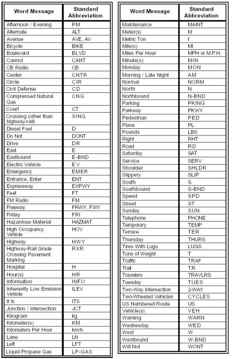
Key changes to Table 1A-1 include: adding abbreviations for the word messages Circle, Court, Inherently Low Emission Vehicle, Parkway, Place, Terrace, Trail, and Vehicle; and changing the abbreviations for the word messages Eastbound, Northbound, Southbound, and Westbound.
15. Page 1A-25, Table 1A-2, Abbreviations That Are Acceptable Only with a Prompt Word. Replace the existing table in its entirety with the following table:
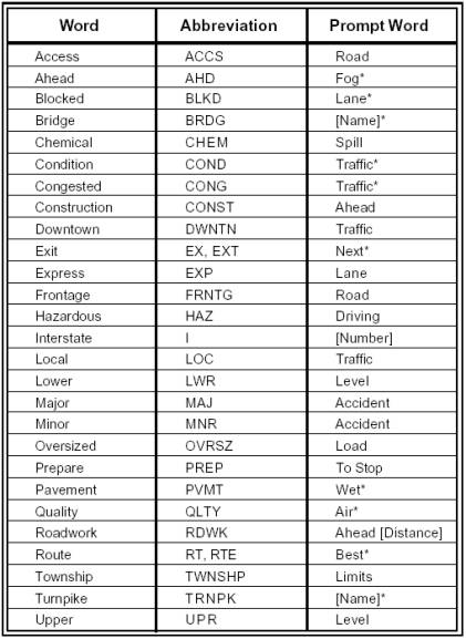
Key changes to Table 1A-2 include: adding a row for the
word Chemical; and removing the rows for the words Eastbound, Northbound,
Southbound, Vehicle, and Westbound.
Part 2
1. Cover of Part 2. Change: “Incorporating: Errata No. 1 dated June 14, 2001” to: “Incorporating: Proposed Revision No. 2, Errata No. 1 dated June 14, 2001.”
2. Page 2A-3, Section 2A.06, Design of Signs. Under Support, in the second paragraph change: “In the specifications for individual signs, the legend, color, and size are shown in the accompanying tables…” to: “In the specifications for individual signs, the general appearance of the legend, color, and size are shown in the accompanying tables…”
3. Page 2A-4, Section 2A.06, Design of Signs. Under Standard, add a new fifth paragraph: “Unless otherwise stated in this Manual for a specific sign, phone numbers or Internet addresses shall not be shown on any sign, supplemental plaque, sign panel (including logo panels on specific service signs), or changeable message sign.”
4. Page 2A-4, Section 2A.07, Changeable Message Signs. Under Standard, change:
Changeable message signs, which are traffic control devices designed to display variable messages, shall conform to the principles established in this Manual, and to the extent practical, with the design and applications prescribed in Sections 6F.52 and 6F.55.
to:
To the extent practical, changeable message signs, which are traffic control devices designed to display variable messages, shall conform to the principles established in this Manual, and with the design and applications prescribed in Sections 2E.21, 6F.02 and 6F.52.
under Guidance, change: “Changeable message signs should not be used to display information other than regulatory, warning, and guidance information related to traffic control.” to: “Except for safety messages, changeable message signs should not be used to display information other than regulatory, warning, and guidance information related to traffic control.”; under Support, in the first paragraph change:
Changeable message signs, with more sophisticated technologies, are gaining widespread use to inform road users of variable situations, particularly along congested traffic corridors. Highway and transportation organizations are encouraged to develop and experiment (see Section 1A.10) with changeable message signs and to carefully evaluate such installations so that additional standards may be adopted in the future.
to:
Changeable message signs, with more sophisticated technologies, are gaining widespread use to inform road users of variable situations, particularly along congested traffic corridors. Highway and transportation organizations are encouraged to develop and experiment (see Section 1A.10) with changeable message signs and to carefully evaluate such installations so that experience is gained toward adoption of future standards.
Under the Support, in the second paragraph, at the end of the first sentence, change: “…Section 6F.02.” to: “…Section 6F.52.”; and under the Support, in the second paragraph, after the first sentence, add “Section 1A.14 contains information regarding the use of abbreviations on traffic control devices, including changeable message signs”; following the Support, add:
Option:
Changeable message signs, both permanent and portable, may be used by State and local highway agencies to display safety or transportation-related messages.
Support:
Examples of safety messages include SEAT BELTS BUCKLED? and DON’T DRINK AND DRIVE. Examples of transportation-related messages include CARPOOL INFO 1-800-XXX-XXXX and OZONE ALERT CODE RED—USE TRANSIT.
Guidance:
When a changeable message sign is used to display a safety or transportation-related message, the requirements of Section 6F.52 should be followed. The message should be simple, brief, legible, and clear. A changeable message sign should not be used to display a safety or transportation-related message if doing so would adversely affect the respect for the sign. “Congestion Ahead” or other overly simplistic or vague messages should not be displayed alone. These messages should be supplemented with a messages on the location or distance to the congestion or incident, how much delay is expected, alternative route, etc.
Standard:
When a changeable message sign is
used to display a safety or transportation-related message, the display format
shall not be of a type that could be considered similar to advertising
displays. The display format shall not
include animation, rapid flashing, or other dynamic elements that are
characteristic of sports scoreboards or advertising displays.
5. Page 2A-5, Section 2A.08, Retroreflectivity and Illumination. Under Standard, in the second paragraph change: “The requirements for sign illumination shall not be considered to be satisfied by street, highway, or strobe lighting.” to: “The requirements for sign illumination shall not be considered to be satisfied by street or highway lighting.”; At the end of the section, add a Support: “Information regarding the use of retroreflective material on the sign support is contained in Section 2A-22.”
6. Page 2A-6, Table 2A-1, Illumination of Sign Elements. Change the fourth row in the first column from: “Other devices, or treatments that highlight the sign shape, color, or message at night: Luminous tubing, Fiber optics (shaped to the lettering or symbol), Patterns of incandescent light bulbs, Luminescent panels” to: “Other devices, or treatments that highlight the sign shape, color, or message: Luminous tubing, Fiber optics, Light emitting diodes (LEDs), Incandescent light bulbs, Luminescent panels”.
7. Page 2A-7, Table 2A-3, Use of Sign Shapes. Remove “Emergency Evacuation Route Marker” from the list of circle signs, change the list of trapezoid signs from: “* Recreational Series” to: “Recreational and Cultural Interest Area Series, National Forest Route Sign”; and in the footnotes to the table change: “* Indicates exclusive use, ** Guide series includes general service, specific service, and recreation signs” to: “* This sign shall be exclusively the shape shown. ** Guide series include general service, specific service, recreation, and emergency management signs.”
8. Page 2A-8, Section 2A.11, Sign Colors. Under Standard, change: “The colors to be used on standard signs and their specific use on these signs shall be as indicated in the specific Sections of Part 2. The color coordinates and values shall be as described in the "Standard Highway Signs" book.” to: “The colors to be used on standard signs and their specific use on these signs shall be as indicated in the applicable Sections of this Manual. The color coordinates and values shall be as described in 23 CFR, Part 655, Subpart F, Appendix.”; under Support, in the third paragraph, change: “The colors purple, light blue, and coral are being reserved for uses that will be determined in the future by the Federal Highway Administration.” to: “The colors purple and light blue are being reserved for uses that will be determined in the future by the Federal Highway Administration”; add a fourth paragraph to the Support: “Information regarding color coding of destinations on guide signs is contained in Section 2D.03.”
9. Page 2A-8, Section 2A.12, Dimensions. Under Support, add a new second paragraph:
The “Standard Highway Signs” book prescribes design details for up to five different sizes depending on the type of traffic facility, including bikeways. Smaller sizes are designed to be used on bikeways and some other off-road applications. Larger sizes are designed for use on freeways and expressways, and can also be used to enhance road user safety and convenience on other facilities, especially on multilane divided highways and on undivided highways having five or more lanes of traffic and/or high speeds. The intermediate sizes are designed to be used on two-lane, three-lane, and four-lane highways that have low speeds and volumes.
10. Page 2A-9. Table 2A-4, Common Uses of Sign Colors. Immediately after the column for “FYG*”, add a new column: “Coral”; immediately after the row for “Temporary Traffic Control” signs, add 2 new rows: “Incident Management” with “X” marks in the “Black” legend column and the “Coral” background column and “Changeable Message Signs **” with “X” marks in the “White” and “Yellow” legend columns and the “Black” background column. Add a new footnote under the table: “** For changeable message signs: FYG pixels may also be used. Reverse colors may also be used.”
11. Page 2A-10, Section 2A.14, Word Messages. Under Guidance, in the first paragraph, change: “Word messages should be as brief as possible and the lettering should be large enough to provide the necessary legibility distance. A specific ratio, such as 25 mm (1 in) of letter height per 12 m (40 ft) of legibility distance, should be used.” to: “Word messages should be as brief as possible and the lettering should be large enough to provide the necessary legibility distance. A minimum specific ratio, such as 25 mm (1 in) of letter height per 12 m (40 ft) of legibility distance, should be used.”; after the first paragraph of Guidance, insert a new Support that reads: “Some research indicates that a ratio of 25 mm (1 in) of letter height per 10 m (33 ft) of legibility distance could be beneficial.”; and insert a Guidance heading before the second paragraph of Guidance.
12. Page 2A-11, Section 2A.15, Sign Borders. Under Standard, in the second paragraph, change: “The corners of the sign shall be rounded,” to: “The corners of all sign borders shall be rounded”; under Guidance, change: “Where practicable, the corners of the sign should be rounded to fit the border, except for STOP signs.” to: “Where practical, the corners of the sign should be rounded to fit the border, except for STOP signs.”
13. Page 2A-11, Section 2A.16, Standardization of Location. Under the first Support, change: “Standardization of position cannot always be attained in practice. Locations for a number of typical signs are illustrated in Figures 2A-1 to 2A-7.” to: “Standardization of position cannot always be attained in practice. Locations for a number of typical signs are illustrated in Figures 2A-1 and 2A-2.”
14. Page 2A-12, Figure 2A-1, Height and Lateral Location of Signs for Typical Installations. Change the Figure title to: “Figure 2A-1. Examples of Heights and Lateral Locations of Signs for Typical Installations”.
15. Page 2A-13, Figure 2A-2, Typical Locations for Signs at Intersections. In the Figure title, change: “Typical” to: “Examples of”; throughout the figure, at each occurrence, change: “3.7 m (12 ft)” to :“MIN. 1.8 m (6 ft) to 3.7 m (12 ft).”
16. Page 2A-14, Figure 2A-3, Typical ONE WAY Signing for Divided Highways with Medians Less Than 9 m (30 ft). Move Figure to follow Section 2B.32, and change Figure number to: “Figure 2B-13”.
17. Page 2A-15, Figure 2A-4, Typical ONE WAY Signing for Divided Highways with Medians Greater Than 9 m (30 ft). Move the Figure to follow Section 2B-32, and change Figure number to: “Figure 2B-12”.
18. Page 2A-16, Figure 2A-5, Typical Locations of ONE WAY Signs. Move the Figure to follow Section 2B-32, and change Figure number to: “Figure 2B.10”.
19. Page 2A-17, Figure 2A-6, Typical Locations of ONE WAY Signs. Move the Figure to follow Section 2B-32, and change Figure number to: “Figure 2B.11”.
20. Page 2A-18, Figure 2A-7, Typical Applications of Warning Signs. Remove the Figure entirely.
21. Page 2A-19, Section 2A.16, Standardization of Location. Under the second Support, in the second sentence change: “The desired width is dependent upon traffic volumes, speeds, and roadside geometry.” to: “The width of the clear zone is dependent upon traffic volumes, speeds, and roadside geometry.”
22. Page 2A-20, Section 2A-17, Overhead Sign Installations. Under Guidance, change: “Overhead signs should be used on expressways, where some degree of lane-use control is desirable, or where space is not available at the roadside.” to: “Overhead signs should be used on freeways and expressways at locations where some degree of lane-use control is desirable or at locations where space is not available at the roadside.”
23. Pages 2A-21 and 2A-22, Section 2A-18, Mounting Height. Under Standard, after the second paragraph, add the headings and paragraphs contained in the first Option and Support statements on Page 2A-22 in their entirety. Following these first Option and Support statements, and prior to the existing third Standard paragraph, add the heading “Standard” and change: “Overhead signs shall…” to: “Overhead mounted signs shall”; in that same paragraph, remove: “ The vertical clearance to overhead sign structures or supports shall not be greater than 0.3 m (1 ft) in excess of the minimum clearance of other structures.”; and following the second Option heading add:
If the vertical clearance for the design of other structures is less than 4.9 m (16 ft), the vertical clearance to overhead sign structures or supports may be as low as 0.3 m (1 ft) higher than the vertical clearance for the design of the other structures.
24. Page 2A-22, Section 2A.19, Lateral Offset. Under the first Standard, change:
The
minimum lateral offset from the edge of the shoulder (or if no shoulder exists,
from the edge of the pavement) to the near edge of a roadside-mounted sign
shall be 1.8 m (6 ft). Roadside-mounted
sign supports shall be breakaway, yielding, or shielded with a longitudinal
barrier or crash cushion if within the clear zone.
The minimum lateral offset from the edge of the shoulder (or if no shoulder exists, from the edge of the pavement) to the near edge of overhead sign supports (cantilever or sign bridges) shall be 1.8 m (6 ft). Overhead sign supports shall have a barrier or crash cushion to shield them if they are within the clear zone.
to:
For
overhead sign supports, the minimum lateral offset from the edge of the
shoulder (or if no shoulder exists, from the edge of the pavement) to the near
edge of overhead sign supports (cantilever or sign bridges) shall be 1.8 m (6
ft). Overhead sign supports shall have
a barrier or crash cushion to shield them if they are within the clear zone.
Roadside-mounted sign supports shall be breakaway, yielding, or shielded with a longitudinal barrier or crash cushion if within the clear zone.
Following the first Standard, insert:
Guidance:
For roadside-mounted signs, the minimum lateral offset should be 3.7 m (12 ft) from the edge of the traveled way. If a shoulder wider than 1.8 m (6 ft) exists, the minimum lateral offset for roadside-mounted signs should be 1.8 m (6 ft) from the edge of the shoulder.
25. Page 2A-23, Section 2A.19, Lateral Offset. Under Support, change: “Figure 2A-1 illustrates…” to: “Figures 2A-1 and 2A-2 illustrate…”
26. Page 2A-23, Section 2A.20, Position of Signs. Under Support, remove the second paragraph.
27. Page 2A-24, Section 2A.22, Posts and Mountings. Following Support, add:
Option:
A strip of retroreflective material may be used on regulatory and warning sign supports to draw attention to the sign during nighttime conditions.
Standard:
If a strip of retroreflective material is used on the sign support, it shall be at least 50 mm (2 in) in width, it shall be placed for the full length of the support from the sign to within 0.3 m (1 ft) of the ground level, and it shall be the same color as the background of the sign (red for STOP, YIELD, DO NOT ENTER, and WRONG WAY; white for regulatory; yellow for warning).
28. Page 2A-25, Section 2A.24, Wrong-Way Traffic Control. Change the Section title to: “Section 2A.24 Median Opening Treatments for Divided Highways with Wide Medians”; change Standard to a Guidance and change: “Where divided highways are separated by median widths of 9 m (30 ft) or more, the intersections with crossroads shall be signed as two separate intersections.” to: “Where divided highways are separated by median widths at the median opening itself of 9 m (30 ft) or more, median openings should be signed as two separate intersections.”; and delete the existing Guidance statement.
29. Page 2B-1, Section 2B.02, Design of Regulatory Signs. Following Support, add:
Option:
Changeable message signs displaying a regulatory message may use a black background with a white, yellow, or fluorescent yellow-green legend and symbol(s) as appropriate.
Guidance:
Changeable message signs displaying a regulatory message incorporating a prohibitory message that includes a red circle and slash on a static sign should display a red symbol that approximates the same red circle and slash as closely as possible.
30. Page 2B-1, Section 2B.03, Size of Regulatory Signs. Under Support, change:
The "Standard Highway Signs" book contains sign sizes and letter heights for regulatory signs used on conventional roads, expressways, freeways, and low-volume roads, and under special conditions.
to:
The “Standard Highway Signs” book prescribes design details for up to five different sizes depending on the type of traffic facility, including bikeways. Smaller sizes are designed to be used on bikeways and some other off-road applications. Larger sizes are designed for use on freeways and expressways, and can also be used to enhance road user safety and convenience on other facilities, especially on multilane divided highways and on undivided highways having five or more lanes of traffic and/or high speeds. The intermediate sizes are designed to be used on two-lane, three-lane, and four-lane highways that have low speeds and volumes.
31. Pages 2B-2 through 2B-5, Table 2B-1, Regulatory Sign Sizes. Replace this table (all sheets) in its entirety with the following table:
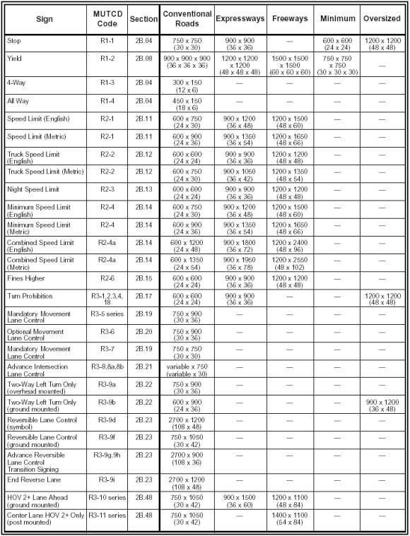
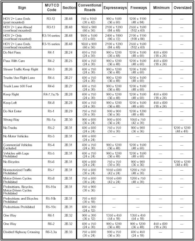
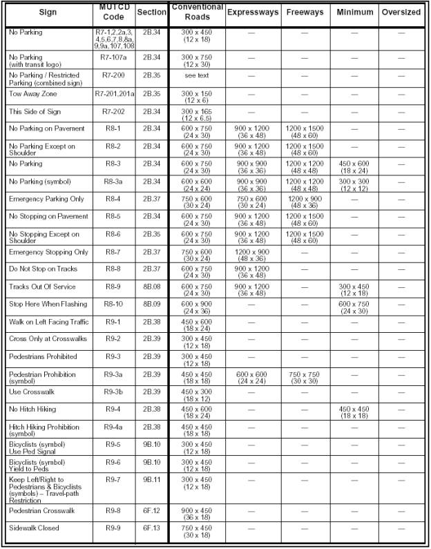
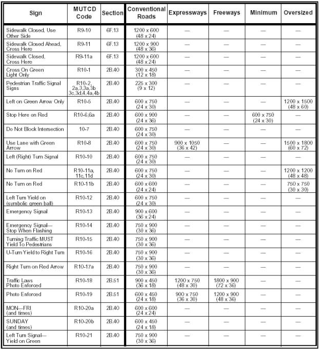
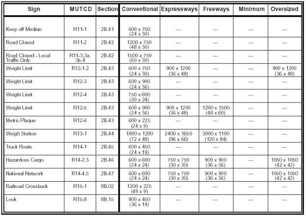
Key changes to Table 2B-1 include adding rows for the following signs Speed Limit (metric), Truck Speed Limit (metric), Minimum Speed Limit (metric), Combined Speed Limit (metric), Fines Higher, Tracks out of Service, Stop Here When Flashing, Sidewalk Closed Cross Here (R9-11), Cross on Green Light Only, Emergency Signal-Stop When Flashing, Turning Traffic MUST Yield to Pedestrians, U-Turn Yield to Right Turn, Right Turn on Red Arrow, Traffic Laws Photo Enforced, Photo Enforced, Mon-Fri (and times), SUNDAY (and times), Left Turn Signal Yield on Green, Metric Plaque, Railroad Crossbuck, and Look; changing sizes for the following signs: One Way (R6-1), One Way (R6-2), Divided Highway Crossing, No Parking/Restricted Parking (combined sign), Do Not Stop on Tracks, Pedestria Crosswalk, Sidewalk Closed, Sidewalk Closed, Use Other Side, Sidewalk Closed Cross Here (R9-11a), Weight Limit; and removing the following signs: Reversible Lane Control (R3-9e), Bicycle Lane Ahead, Bicycle Lane Ends, Right Lane Bicycle Only, Bicycle Lane with Vehicle Parking, and Seat Belt Symbol.
32. Page 2B-6, Section 2B.03, Size of Regulatory Signs. Under Option, change: “The minimum size may be used on low-speed roadways where reduced legend size…” to: “The minimum size may be used on low-speed roadways where the reduced legend size…”, change the second paragraph from: “The Oversized size may be used for those special applications that require increased emphasis, improved recognition, or increased legibility.” to: “The Oversized size may be used for those special applications where speed, volume, or other factors result in conditions where increased emphasis, improved recognition, or increased legibility would be desirable.”; and add a third paragraph to the Option that reads, “Signs larger than those shown in Table 2B-1 may be used (see Section 2A.12).”
33. Page 2B-6, Section 2B.04, STOP Sign (R1-1). Under Standard, in the first paragraph, change: “When a sign is used to indicate that traffic is always required to stop, a STOP (R1-1) sign shall be used.” to: “When a sign is used to indicate that traffic is always required to stop, a STOP (R1-1) sign (see Figure 2B-1) shall be used.”; and in the third sentence of the second paragraph, change: “Such plaques shall…” to: “Such plaques (see Figure 2B-1) shall…”.
34. Page 2B-7. Add a figure number and title to this page of sign images: “Figure 2B-1 STOP, YIELD, Speed Limit, FINES HIGHER, and Photo Enforcement Signs”; revise the metric Speed Limit (R2-1 and R2-2) signs by removing the METRIC plaque and the km/h plaque and by adding a red circle around the speed value; and add sign images for the FINES HIGHER (R2-6), PHOTO ENFORCED (R10-19), and TRAFFIC LAWS PHOTO ENFORCED (R10-18) signs.
35. Page 2B-8, Section 2B.05, STOP Sign Applications. Under Guidance, change: “STOP signs should not be used unless engineering judgment indicates that one or more of the following conditions exist:” to: “STOP signs should be used if engineering judgment indicates that one or more of the following conditions exist:”; change item A from: “Intersection of a less important road with a main road where application of the normal right-of-way rule would not be expected to provide reasonably safe operation;” to: “Intersection of a less important road with a main road where application of the normal right-of-way rule would not be expected to provide reasonable compliance with the law.”; change item D from: “High speeds, restricted view, or crash records indicate that a need for control by the STOP sign.” to: “High speeds, restricted view, or crash records indicate a need for control by the STOP sign.”.
36. Page 2B-9, Section 2B.05, STOP Sign Applications. Under Support, in the last paragraph, change: “The use of the STOP sign at highway-railroad grade crossings is described in Section 8B.07.” to: “The use of the STOP sign at highway-railroad grade crossings is described in Section 8B.07. The use of the STOP sign at highway-light rail transit grade crossings is described in Section 10C.04.”
37. Page 2B-9, Section 2B.06, STOP Sign Placement. Under Standard, in the first paragraph, in the first sentence, change: “The STOP sign shall be installed on the correct side…” to: “The STOP sign shall be installed on the right side…”; and insert a new fourth paragraph that reads, “ Other than a DO NOT ENTER sign, no sign shall be mounted back-to-back with a STOP sign.” Under Guidance, in the third paragraph, change: “Where two roads intersect at an acute angle, the STOP sign should be positioned at an angle or else shielded so that the legend is out of view of traffic to which it does not apply.” to: “Where two roads intersect at an acute angle, the STOP sign should be positioned at an angle, or shielded, so that the legend is out of view of traffic to which it does not apply.”
38. Page 2B-11, Section 2B.08, YIELD Sign
(R1-2). Under Standard, change: “The YIELD (R1-2) sign shall…” to: “The
YIELD (R1-2) sign (see Figure 2B-1) shall…”
39. Page 2B-12, Section 2B.09, YIELD Sign
Applications. Under Option, change: “YIELD signs may be installed:” to:
“YIELD signs may be used instead of STOP signs if engineering judgment
indicates that one or more of the following conditions exist:”; under item C,
change: “At the second crossroad of a divided highway, where the median width
is 9 m (30 ft) or greater. A STOP
sign…” to: “At the second crossroad of a divided highway, where the median
width is 9 m (30 ft) or greater, at the intersection itself, a STOP sign…”
Following the Option, add a Standard statement that reads: “A YIELD (R1-2) sign
shall be used to assign right-of-way at the entrance to a roundabout
intersection.”
40. Page 2B-12, Section 2B.10, YIELD Sign Placement. Under Standard, in the first sentence, change: “The YIELD sign shall be installed on the correct side of the traffic lane to which it applies.” to: “The YIELD sign shall be installed on the right side of the traffic lane to which it applies.”; before the second sentence, add a new sentence that reads: “YIELD signs shall be placed on both the left and right sides of approaches to roundabout intersections with more than one approach lane.”; and add a fourth paragraph that reads: “Other than a DO NOT ENTER sign, no sign shall be mounted back-to-back with a YIELD sign”. Under Guidance, change: “YIELD lines, when used…” to: “Yield lines, when used…”; following the third paragraph, add a new paragraph that reads: “At a roundabout intersection, to prevent circulating vehicles from yielding unnecessarily, the face of the YIELD sign should not be visible from the circular roadway”; and following Guidance, add:
Option:
At wide-throat intersections or where two or more approach lanes of traffic exist on the signed approach, observance of the yield control may be improved by the installation of an additional YIELD sign on the left side of the road and/or the use of a yield line. At channelized intersections, the additional YIELD sign may be effectively placed on a channelizing island.
41. Page 2B-13, Section 2B.11, Speed Limit Sign (R2-1). Under Standard, in the first sentence, change: “…the Speed Limit (R2-1) sign shall display the limit established by law, ordinance, regulation, or as adopted by the authorized agency.” to: “…the Speed Limit (R2-1) sign (see Figure 2B-1) shall display the limit established by law, ordinance, regulation, or as adopted by the authorized agency.”; delete the second Standard paragraph; and following Standard, delete the Support. Under Guidance, add the following paragraph at the beginning: “States and local agencies should reevaluate the non-statutory speed limits on their streets and highways at least once every 5 years to determine if any adjustments would be appropriate.”; and in the second paragraph, change: “When a speed limit is to be posted, it should be the 85th-percentile speed of free-flowing traffic, rounded up to the nearest 10 km/h (5 mph) increment.” to: “When a speed limit is to be posted, it should be the 85th-percentile speed of free-flowing traffic, rounded up to the nearest 10 km/h (5 mph) increment on non-residential streets and rounded up or down to the nearest 10 km/h (5 mph) increment on residential streets.” Under Option, in the third paragraph, change: “A changeable message sign that changes for traffic and ambient conditions…” to: “A changeable message sign that changes the speed limit for traffic and ambient conditions…”; at the end of the Option, add the following paragraph: “A changeable message sign that displays to approaching drivers the speed at which they are traveling may be installed in conjunction with a Speed Limit sign.”; and following the Option, add a Guidance statement: “If a changeable message sign displaying approach speeds is installed, the legend YOUR SPEED XX km/h (MPH) or such similar legend should be shown.”
42. Page 2B-14, Section 2B.12, Truck Speed Limit Sign (R2-2). Under Standard, change: “Where a special speed limit applies to trucks or other vehicles, the legend TRUCKS XX or such similar legend shall be shown on the same panel as the Speed Limit sign or on a separate sign (R2-2) below the standard legend.” to: “Where a special speed limit applies to trucks or other vehicles, the legend TRUCKS XX or such similar legend shall be shown on the same panel as the Speed Limit sign or on a separate R2-2 sign (see Figure 2B-1) below the standard legend.”
43. Page 2B-14, Section 2B.13 Night Speed Limit Sign (R2-3). Under Guidance, change: “A Night Speed Limit (R2-3) sign should…” to: “A Night Speed Limit (R2-3) sign (see Figure 2B-1) should…”
44. Page 2B-14, Section 2B.14, Minimum Speed Limit Sign (R2-4). Under Standard, change: “A Minimum Speed Limit (R2-4) sign shall be displayed…” to: “A Minimum Speed Limit (R2-4) sign (see Figure 2B-2) shall be displayed…”; and under Option, in the last sentence, change: “If desired, these two signs may be combined on the R2-4a sign.” to: “If desired, these two signs may be combined on the R2-4a sign (see Figure 2B-2).”
45. Page 2B-15. Add a figure number and title to this page of sign images: “Figure 2B-2. Speed Limit and Turn Prohibition Signs”; revise the metric Speed Limit (R2-4 and R2-4a) signs by removing the METRIC plaque and the km/h plaque and by adding a red circle around the speed value; remove the Reduced Speed (R2-5 series) signs; and add the red combination No U-Turn/No Left Turn (R3-18) sign.
46. Page 2B-16. Following Section 2B-14, insert a new Section numbered and titled, “Section 2B.15, FINES HIGHER Sign (R2-6)”. The new Section reads:
Option:
The FINES HIGHER (R2-6) sign (see Figure 2B-1) may be used to advise road users when increased fines are imposed for traffic violations within designated roadway segments.
The FINES HIGHER sign may be mounted below an applicable regulatory or warning sign in a temporary traffic control zone, a school zone, or other applicable designated zones.
The following may be mounted below the FINES HIGHER sign:
A. A supplemental plaque specifying the times that the higher fines are in effect (similar to the S4-1 plaque shown in Figure 7B-1); or
B. A supplemental plaque WHEN CHILDREN (WORKERS) ARE PRESENT (similar to the S4-2 plaque shown in Figure 7B-1); or
C. A supplemental plaque WHEN FLASHING (similar to the S4-4 plaque shown in Figure 7B-1) if used in conjunction with a yellow flashing beacon.
The legend FINES HIGHER may be replaced by multiple values such as FINES DOUBLE or FINES TRIPLE, or by a specific value such as $150 FINE.
Standard:
The FINES HIGHER sign shall be a rectangle with a black legend and
border on a white background.
All supplemental plaques mounted
below the FINES HIGHER sign shall be rectangles with black legends and borders
on white backgrounds.
The FINES HIGHER sign shall include a SCHOOL, WORK ZONE, or other applicable designated zone plaque mounted above the applicable regulatory or warning sign. The SCHOOL supplemental plaque shall be rectangular in shape with a black legend on a yellow or fluorescent yellow-green background (same as S4-3). The WORK ZONE supplemental plaque shall be rectangular in shape with a black legend on an orange background.
Guidance:
If used, the FINES HIGHER sign should be located at the beginning of the temporary traffic control zone, school zone, or other applicable designated zone and just beyond any interchanges, major intersections, or other major traffic generators.
Agencies should limit the use of the FINES HIGHER sign to locations where work is actually underway, or to locations where the roadway, shoulder, or other conditions, including the presence of a school, require a speed reduction or extra caution on the part of the road user.
47. Page 2B-16, Section 2B.15, Location of Speed Limit Signs. Change the Section number to: “Section 2B.16”
48. Page 2B-16, Section 2B.16, Reduced Speed Ahead Signs (R2-5 Series). Delete this section in its entirety.
49. Page 2B-17, Section 2B.17, Turn Prohibition Signs (R3-1 through R3-4). Change the Section title to: “Section 2B.17, Turn Prohibition Signs (R3-1 through R3-4 and R3-18)”; under Guidance, change:
Turn Prohibition signs should be placed where they will be most easily seen by road users who might be intending to turn.
If No Right Turn (R3-1) signs are used, at least one should be placed either over the roadway or at a right corner of the intersection.
If No Left Turn (R3-2) signs are used, at least one should be placed either over the roadway, at a left corner of the intersection, on a median, or in conjunction with the STOP sign or YIELD sign located on the near right corner.
Except as noted in the Option, if NO TURNS (R3-3) signs are used, two signs should be used, one at a location specified for a No Right Turn sign and one at a location specified for a No Left Turn sign.
If No U-Turn (R3-4) signs are used, at least one should be used at a location specified for No Left Turn signs.
to:
Turn Prohibition signs should be placed where they will be most easily seen by road users who might be intending to turn.
If No Right Turn (R3-1) signs (see Figure 2B-2) are used, at least one should be placed either over the roadway or at a right corner of the intersection.
If No Left Turn (R3-2) signs (see Figure 2B-2) are used, at least one should be placed either over the roadway, at the far left corner of the intersection, on a median, or in conjunction with the STOP sign or YIELD sign located on the near right corner.
Except as noted in the Option, if NO TURNS (R3-3) signs (see Figure 2B-2) are used, two signs should be used, one at a location specified for a No Right Turn sign and one at a location specified for a No Left Turn sign.
If No U-Turn (R3-4) signs (see Figure 2B-2) are used, at least one should be used at a location specified for No Left Turn signs.
If combination No U-Turn/No Left Turn (R3-18) signs (see Figure 2B-2) are used, at least one should be used at a location specified for No Left Turn signs.
Under Option, in item B, change “The No Left Turn (or No U-Turn) sign may be installed adjacent to a signal face viewed by road users in the left lane.” to “The No Left Turn (or No U-Turn or combination No U-Turn/No Left Turn) sign may be installed adjacent to a signal face viewed by road users in the left lane.”
50. Page 2B-18, Section 2B.17, Turn Prohibition Signs (R3-1 through R3-4). Under Option, after the last paragraph, add a new paragraph: “If both left turns and U-turns are prohibited, the R3-18 sign may be used instead of separate R3-2 and R3-4 signs.”
51. Page 2B-18, Section 2B.18, Intersection Lane Control Signs (R3-5 through R3-8). Under the first Standard, in the second paragraph, change: “Intersection Lane Control signs shall have three applications:” to: “Intersection Lane Control signs (see Figure 2B-3) shall have three applications.”; under Guidance, change: “When used, Intersection Lane Control signs should be mounted overhead, and each sign should be placed over a projection of the lane to which it applies.” to: “When Intersection Lane Control signs are mounted overhead, each sign should be placed over the lane or a projection of the lane to which it applies.”
52. Page 2B-19. Add a Figure number and title to this page of sign images: “Figure 2B-3. Intersection Lane Use Control Signs.”
53. Page 2B-20, Section 2B.19, Mandatory Movement Lane Control Signs (R3-5, R3-5a, and R3-7). Under Standard, in the first paragraph, in the first sentence, change: “If used, Mandatory Movement Lane Control signs (R3-5, R3-5a, and R3-7) shall indicate…” to: “If used, Mandatory Movement Lane Control (R3-5, R3-5a, and R3-7) signs (see Figure 2B-3) shall indicate…”; and in the second paragraph, in the first sentence, change: “If the R3-5 sign is ground mounted on a multilane approach, a supplemental plaque…” to: “If the R3-5 sign is ground mounted on a multilane approach, a supplemental plaque (see Figure 2B-3)…”. Under Guidance, change: “If used, Mandatory Movement Lane Control signs should be accompanied by lane control pavement markings, especially where traffic volumes are high, where there is a high percentage of commercial vehicles, or where other distractions exist.” to: “Mandatory Movement Lane Control signs should be accompanied by lane use arrow markings, especially where traffic volumes are high, where there is a high percentage of commercial vehicles, or where other distractions exist.”
54. Page 2B-21, Section 2B.20, Optional Movement Lane Control Sign (R3-6). Under Standard, in the first paragraph, in the first sentence, change: “If used, the Optional Movement Lane Control (R3-6) sign shall be used…” to: “If used, the Optional Movement Lane Control (R3-6) sign (see Figure 2B-3) shall be used…”
55. Page 2B-21, Section 2B.21, Advance Intersection Lane Control Signs (R3-8 Series). Under Option, in the first paragraph, change: “Advance Intersection Lane Control (R3-8, R3-8a, and R3-8b) signs may be used to indicate the configuration of all lanes ahead.” to: “Advance Intersection Lane Control (R3-8, R3-8a, and R3-8b) signs (see Figure 2B-3) may be used to indicate the configuration of all lanes ahead.”
56. Page 2B-22, Section 2B.22, Two-Way Left Turn Only Signs (R3-9a, R3-9b). Under Guidance, change: “Two-Way Left Turn Only (R3-9a or R3-9b) signs should be used…” to: “Two-Way Left Turn Only (R3-9a or R3-9b) signs (see Figure 2B-4) should be used…”
57. Page 2B-22, Section 2B.23, Reversible Lane Control Signs (R3-9c through R3-9i). Change the Section title to: “Section 2B.23, Reversible Lane Control Signs (R3-9d, R3-9f through R3-9i)”; under the first Option, in the second sentence, change: “Reversible Lane Control (R3-9c through R3-9i) signs may either be static type or changeable message type.” to: “Reversible Lane Control (R3-9d, R3-9f through R3-9i) signs (see Figure 2B-4) may either be static type or changeable message type.”
58. Page 2B-23. Add a Figure number and title to this page of sign images: “Figure 2B-4. Center and Reversible Lane Control Signs”; and remove the R3-9c and R3-9e signs from the figure.
59. Page 2B-24, Section 2B.23, Reversible Lane Control Signs (R3-9d, R3-9f through R3-9i). Under the first Standard, in the second paragraph, change: “Where it is determined by an engineering study that lane-use control signals or barriers are not necessary, the lane shall be controlled by overhead Reversible Lane Control signs (see Figure 2B-1).” to: “Where it is determined by an engineering study that lane-use control signals or physical barriers are not necessary, the lane shall be controlled by overhead Reversible Lane Control signs (see Figure 2B-5).”; and under the Option, change item B from: “An engineering study indicates that sign operation alone would result in a level of safety and efficiency that is acceptable.” to: “An engineering study indicates that the use of Reversible Lane Control signs alone would result in an acceptable level of safety and efficiency.” Under the second Standard, in the second paragraph, change: “…except for the R3-9c and R3-9d signs, where the color red is used.” to: “…except for the R3-9d signs, where the color red is used.”; in the third paragraph, change:
Symbol signs, such as the R3-9c or R3-9d signs, shall consist of the appropriate symbol in the upper portion of the sign with the appropriate times of the day and days of the week below it. Where word message signs, such as R3-9e, are used, the times of the day and the days of the week, when appropriate, shall be on the right portion of the sign and the appropriate legend to the left. All times of the day and days of the week shall be accounted for on the sign to eliminate confusion to the road user.
to:
Symbol signs, such as the R3-9d sign, shall consist of the appropriate symbol in the upper portion of the sign with the appropriate times of the day and days of the week below it. All times of the day and days of the week shall be accounted for on the sign to eliminate confusion to the road user.
Under the second Standard, in the fourth paragraph, change: “In situations where more than one message is conveyed to the road user, such as on the R3-9d or R3-9e signs…” to: “In situations where more than one message is conveyed to the road user, such as on the R3-9d sign…”
60. Page 2B-25. Figure 2B-1, Location of Reversible Two-Way Left-Turn Signs. Change the Figure number to: “Figure 2B-5.”
61. Page 2B-26. Table 2B-2 Meanings of Symbols and Legends on Reversible Lane Control Signs. Change the first column, second row from: “Red X on white background or symbolic DO NOT ENTER sign.” to: “Red X on white background.”
62. Page 2B-28, Section 2B.24, DO NOT PASS Sign (R4-1). Under Option, in the first paragraph, in the first sentence, change: “The DO NOT PASS (R4-1) sign may be used…” to: “The DO NOT PASS (R4-1) sign (see Figure 2B-6) may be used…”
63. Page 2B-28, Section 2B.25, PASS WITH CARE Sign (R4-2). Under Guidance, change: “The PASS WITH CARE (R4-2) sign should be installed at the end of a no-passing zone…” to: “The PASS WITH CARE (R4-2) sign (see Figure 2B-6) should be installed at the end of a no-passing zone...”
64. Page 2B-28, Section 2B.26, SLOWER TRAFFIC KEEP RIGHT Sign (R4-3). Under Option, change: “The SLOWER TRAFFIC KEEP RIGHT (R4-3) sign may be used…” to: “The SLOWER TRAFFIC KEEP RIGHT (R4-3) sign (see Figure 2B-6) may be used…”; under Guidance, in the first sentence, change: “If used, the SLOWER TRAFFIC KEEP RIGHT (R4-3) sign should be installed…” to: “If used, the SLOWER TRAFFIC KEEP RIGHT sign should be installed…”
65. Page 2B-29. Add a Figure number and title to this page of sign images: “Figure 2B-6. Passing and Keep Right Signs”.
66. Page 2B-30, Section 2B.27, Slow Moving Traffic Lane Signs (R4-5, R4-6). Under Support, in the first paragraph, change: “The Slow Moving Traffic Lane signs are used to direct vehicles into an extra lane…” to: “The Slow Moving Traffic Lane signs (see Figure 2B-6) are used to direct vehicles into an extra lane…”; under Option, in the first sentence, change: “The SLOWER TRAFFIC KEEP RIGHT sign may be used as a supplement or as an alternative to the TRUCKS USE RIGHT LANE (R4-5).” to: “The SLOWER TRAFFIC KEEP RIGHT sign may be used as a supplement or as an alternative to the TRUCKS USE RIGHT LANE sign.”
67. Page 2B-30, Section 2B.28, Keep Right and Keep Left Signs (R4-7, R4-8). Under the first Option change:
The Keep Right (R4-7) sign may be used at locations where it is necessary for traffic to pass only to the right of a roadway feature or obstruction.
to:
The Keep Right (R4-7) sign (see Figure 2B-6) may be used at locations where it is necessary for traffic to pass only to the right of a roadway feature or obstruction. The Keep Left (R4-8) sign (see Figure 2B-6) may be used at locations where it is necessary for traffic to pass only to the left of a roadway feature or obstruction.
Under Guidance, in the second sentence, change: “The sign should be mounted on the face of or just in front of a pier or other obstruction separating opposite directions of traffic in the center of the highway.” to: “The sign should be mounted on the face of or just in front of a pier or other obstruction separating opposite directions of traffic in the center of the highway such that traffic will have to pass to the right of the sign.”; following Guidance, add a Standard statement that reads: “The Keep Right sign shall not be installed on the right side of the roadway in a position where traffic must pass to the left of the sign.”; and under the second Option, in the second paragraph, change: “The word message KEEP RIGHT (LEFT) with an arrow (R4-7a or R4-7b) may be used instead of the R4-7 symbol sign.” to: “Word message KEEP RIGHT (LEFT) with an arrow (R4-7a or R4-7b) signs (see Figure 2B-6) may be used instead of the R4-7 or R4-8 symbol signs (see Figure 2B-6).”
68. Page 2B-31, Section 2B.28, Keep Right and Keep Left Signs. Under the second Option, remove the third paragraph: “Where appropriate, a Keep Left (R4-8) symbol sign (see Figure 2B-6) may be used.”
69. Page 2B-31, Section 2B.29, DO NOT ENTER Sign (R5-1). Under Standard, change: “The DO NOT ENTER (R5-1) sign shall be used where traffic is prohibited from entering a restricted roadway.” to: “The DO NOT ENTER (R5-1) sign (see Figure 2B-7) shall be used where traffic is prohibited from entering a restricted roadway.”; under Guidance, in the first paragraph, in the first sentence, change: “The DO NOT ENTER sign, if used, should be placed at the point where a road user could wrongly enter a one-way roadway or ramp.” to: “The DO NOT ENTER sign, if used, should be placed directly in view of a road user at the point where a road user could wrongly enter a divided highway, one-way roadway, or ramp (see Figure 2B-8).”; under Option, in the second paragraph, change: “A second DO NOT ENTER sign on the left side of the roadway may be used, particularly where traffic approaches from an intersecting roadway (see Figures 2A-3 and 2B-2).” to: “A second DO NOT ENTER sign on the left side of the roadway may be used, particularly where traffic approaches from an intersecting roadway (see Figure 2B-8).”
70. Page 2B-31, Section 2B.30, WRONG-WAY Sign (R5-1a). Under Option, change:
The WRONG WAY (R5-1a) sign may be used as a supplement to the DO NOT ENTER sign where an exit ramp intersects a crossroad or a crossroad intersects a one-way roadway in a manner that does not physically discourage or prevent wrong-way entry (see Figures 2A-3 and 2B-2).
to:
The WRONG WAY (R5-1a) sign (see Figure 2B-7) may be used as a supplement to the DO NOT ENTER sign where an exit ramp intersects a crossroad or a crossroad intersects a one-way roadway in a manner that does not physically discourage or prevent wrong-way entry (see Figure 2B-8).
71. Page 2B-32. Add a Figure number and title to this page of sign images: “Figure 2B-7. Traffic Prohibition Signs”; and remove the border from the DO NOT ENTER (R5-1) sign.
72. Page 2B-33. Figure 2B-2 Typical Wrong-Way Signing for Divided Highways. Change the figure number and title to: “Figure 2B-8. Example of Wrong-Way Signing for a Divided Highway with a Median Width of 9m (30 ft) or Greater”; and add dimensions indicating the median width to the figure.
73. Page 2B-34, Section 2B.31, Selective Exclusion Signs. Under the first Support, change: “Selective Exclusion signs give notice to road users…” to: “Selective Exclusion signs (see Figure 2B-7) give notice to road users…”; and under the second Support, change Item H from: “Hazardous Cargo Prohibited (R14-3).” to: “Hazardous Material Prohibited (R14-3) (see Figure 2B-20).”
74. Page 2B-35, Section 2B.32, ONE WAY Signs (R6-1, R6-2). Under the first Standard, change:
Except as noted in the Option, the ONE WAY (R6-1 or R6-2) sign shall be used to indicate streets or roadways upon which vehicular traffic is allowed to travel in one direction only.
ONE WAY signs shall be placed parallel to the one-way street at all alleys and roadways that intersect one-way roadways.
to:
Except as noted in the Option,
the ONE WAY (R6-1 or R6-2) sign (see Figure 2B-9) shall be used to indicate
streets or roadways upon which vehicular traffic is allowed to travel in one
direction only.
ONE WAY signs shall be placed parallel to the one-way street at all alleys and roadways that intersect one-way roadways as shown in Figures 2B-10 through 2B-14.
Under Guidance, change:
Where divided highways are separated by median widths of 9 m (30 ft) or more, ONE WAY signs (see Section 2B.32) should be placed, visible to each crossroad approach, on the near right and far left corners of each intersection with the directional roadways as shown in Figures 2A-4 and 2A-5.
to:
Where divided highways are separated by median widths at the intersection itself of 9 m (30 ft) or more, ONE WAY signs should be placed, visible to each crossroad approach, on the near right and far left corners of each intersection with the directional roadways as shown in Figures 2B-10 and 2B-12.
Under Option, in the second paragraph, change: “ONE WAY signs may be omitted at intersections with divided highways that have median widths of less than 9 m (30 ft).” to: “ONE WAY signs may be omitted (see Figure 2B-13) at intersections with divided highways that have median widths at the intersection itself of less than 9 m (30 ft).”; and remove the Support statement.
75. Page 2B-36. Add a number and title to the illustration: “Figure 2B-9. ONE WAY and Divided Highway Crossing Signs”.
76.
Following Section 2B.32, Insert old Figure 2A-5,
renumbered and retitled as: “Figure 2B-10. Examples of Locations of ONE WAY
Signs”; then insert old Figure 2A-6, renumbered and retitled as: “Figure
2B-11. Examples of Locations of ONE WAY Signs” then insert old Figure 2A-4,
renumbered and retitled as: “Figure 2B-12. Examples of ONE WAY Signing for
Divided Highways with Medians of 9m (30 ft) or Greater”; in old Figure 2A-4,
revise the signs shown under the Stop signs to include the words “DIVIDED” and
“HIGHWAY” in addition to the arrows and add at the bottom of the figure: “Note:
See Figure 2B-8 for examples of placing DO NOT ENTER and WRONG WAY signing.” Then insert old Figure 2A-3, renumbered and
retitled as: “Figure 2B-13. Examples of ONE WAY Signing for Divided Highways
with Medians Less Than 9m (30 ft)”; in old figure 2A-3, remove the DO NOT
ENTER and WRONG WAY signs from the figure and add symbolic Keep Right signs in
the median at approximately 45-degree angles, add dimensions to the median, add
asterisks to all signs except the Stop signs and in the legend, add “*
Optional”; and then insert new Figure 2B-14. “Examples of ONE WAY
Signing for Divided Highways with Medians Less Than 9 m (30 ft) and Separated
Left-Turn Lanes”.
77. Page 2B-36, Section 2B.33, Divided Highway Crossing Signs (R6-3, R6-3a). Under first Option, change: “The Divided Highway Crossing (R6-3 or R6-3a) sign may be used to advise road users…” to: “The Divided Highway Crossing (R6-3 or R6-3a) sign (see Figure 2B-9) may be used to advise road users…”
78. Page 2B-37, Section 2B.34, Parking, Standing, and Stopping Signs (R7 and R8 Series). Under Support, in the second sentence, change: “Typical examples of parking, stopping, and standing signs are as follows:” to: “Typical examples of parking, stopping, and standing signs (see Figures 2B-15 and 2B-16) are as follows:”.
79. Page 2B-38. Add a Figure number and title to this page of sign images: “Figure 2B-15. No Parking Signs (R7 Series)”.
80. Page 2B-39. Add a Figure number and title to this page of sign images: “Figure 2B-16. No Parking Signs (R8 Series)”.
81. Page 2B-40, Section 2B.35, Design of Parking, Standing, and Stopping Signs. Under Guidance, combine the last three paragraphs (following Item C) into one paragraph; and insert a new final paragraph:
Where special parking restrictions are imposed during heavy snow-fall, Snow Emergency signs should be installed. The legend will vary according to the regulations, but the signs should be vertical rectangles, having a white background with the upper part of the plate a red background.
Under Option, in Item B of the third paragraph, change: “The red Parking Prohibition sign and the green Permissive Parking sign may be combined on a single…” to: “The red Parking Prohibition sign and the green Permissive Parking sign may be combined to form an R7-200 sign on a single…”; in the sixth paragraph, in the first sentence, change: “Alternate designs for the R7-107 sign may be developed such as the R7-107a sign.” to: “Alternate designs for the R7-107 sign may be developed such as the R7-107a sign (see Figure 2B-15).”; in the seventh paragraph, in the first sentence, change: “To make the parking regulations more effective and to improve public relations by giving a definite warning, a sign reading TOW-AWAY ZONE (R7-201) may be appended to,…” to: “To make the parking regulations more effective and to improve public relations by giving a definite warning, a sign (see Figure 2B-15) reading TOW-AWAY ZONE (R7-201) may be appended to,…”; in the eighth paragraph in the fourth sentence, change: “Word message supplemental plaques, such as ON PAVEMENT (R8-3c) or ON BRIDGE (R8-3d), may be mounted below the R8-3 or R8-3a sign.” to: “Word message supplemental plaques (see Figure 2B-16), such as ON PAVEMENT (R8-3c) or ON BRIDGE (R8-3d), may be mounted below the R8-3 or R8-3a sign.”
82. Page 2B-42, Section 2B.37, Emergency Restriction Signs (R8-4, R8-7, R8-8). Under Option, in the first paragraph, change: “The EMERGENCY PARKING ONLY (R8-4) sign or the EMERGENCY STOPPING ONLY (R8-7) sign may be used…” to: “The EMERGENCY PARKING ONLY (R8-4) sign (see Figure 2B-16) or the EMERGENCY STOPPING ONLY (R8-7) sign (see Figure 2B-16) may be used…”; and in the second paragraph, change: “The DO NOT STOP ON TRACKS (R8-8) sign may be used to discourage or prohibit parking or stopping on railroad tracks (see Section 8B.06).” to: “The DO NOT STOP ON TRACKS (R8-8) sign (see Figure 8B-4) may be used to discourage or prohibit parking or stopping on railroad tracks (see Section 8B.06).”
83. Page 2B-42, Section 2B.38, WALK ON LEFT FACING TRAFFIC and No Hitchhiking Signs (R9-1, R9-4, R9-4a). Under the first Option, change: “The WALK ON LEFT FACING TRAFFIC (R9-1) sign may be used on highways where no sidewalks are provided.” to: “The WALK ON LEFT FACING TRAFFIC (R9-1) sign (see Figure 2B-17) may be used on highways where no sidewalks are provided.”
84. Page 2B-43. Add a Figure number and title to this page of sign images: “Figure 2B-17, Pedestrian Crossing Signs”; at the beginning of the fourth row add an R10-3d “START CROSSING TO MEDIAN…” sign image; add an R10-3e “START CROSSING” sign following R10-3d; and remove the R10-5 “LEFT ON GREEN ARROW ONLY” sign image.
85.
Page 2B-44, Section
2B.38, WALK ON LEFT FACING TRAFFIC and No Hitchhiking Signs (R9-1, R9-4,
R9-4a). Under the Option, change: “The
No Hitchhiking (R9-4a) sign may be used to prohibit standing in or adjacent to
the roadway for the purpose of soliciting a ride. The R9-4 word message sign may be used as an alternate to the
R9-4a symbol sign.” to: “The No Hitchhiking (R9-4a) sign (see Figure 2B-17) may
be used to prohibit standing in or adjacent to the roadway for the purpose of
soliciting a ride. The R9-4 word
message sign (see Figure 2B-17) may be used as an alternate to the R9-4a symbol
sign.”
86. Page 2B-44, Section 2B.39, Pedestrian Crossing Signs (R9-2, R9-3). Under the first Option, change: “Pedestrian Crossing signs may be used to limit pedestrian crossing to specific locations.” to: “Pedestrian Crossing signs (see Figure 2B-17) may be used to limit pedestrian crossing to specific locations.” and under the second Option, in the third paragraph, in the first sentence, change: “The PEDESTRIANS PROHIBITED (R9-3) word message sign may be used as an alternate to the R9-3a symbol sign.” to: “The NO PEDESTRIAN CROSSING (R9-3) word message sign may be used as an alternate to the R9-3a symbol sign.”
87. Page 2B-44, Section 2B.40, Traffic Signal Signs (R10-1 through R10-13). Change the Section title to: “Section 2B.40. Traffic Signal Signs (R10-1 through R10-21)”; and under Option, change: “To supplement traffic signal control, Traffic Signal signs R10-1 through R10-13 may be used to regulate road users.” to: “To supplement traffic signal control, Traffic Signal signs R10-1 through R10-16 may be used to regulate road users.”
88. Page 2B-45, Section 2B.40, Traffic Signal Signs (R10-1 through R10-13). Under the first Standard, change: “Traffic signal signs applicable to pedestrian actuation shall be mounted immediately above or incorporated in pedestrian pushbutton units (see Section 4E.07). Traffic Signal signs applicable to pedestrians include:” to: “Traffic Signal signs applicable to pedestrian actuation (see Figure 2B-17) shall be mounted immediately above or incorporated in pedestrian pushbutton units (see Section 4E.08). Traffic Signal signs applicable to pedestrians include:”. Under the Option, in the second paragraph, in the third sentence, change:
Where word-type pedestrian signal indications are being retained for the remainder of their useful service life, the legends WALK/DONT WALK may be substituted for the symbols on the educational plaque R10-3b, thus creating sign R10-3c.
to:
Where word-type pedestrian signal indications are being retained for the remainder of their useful service life, the legends WALK/DONT WALK may be substituted for the symbols on the educational plaque R10-3b, thus creating sign R10-3c. The R10-3d sign may be used if the pedestrian clearance time is sufficient only for the pedestrian to cross to the median.
Under the Option, in the third paragraph, in the first sentence, change: “Traffic Signal signs may be installed at certain locations to clarify signal control.” to: “Traffic Signal signs (see Figure 2B-18) may be installed at certain locations to clarify signal control.”
89. Page 2B-46. Add a Figure number and title to this page of sign images: “Figure 2B-18. Traffic Signal Signs”; add sign images for the LEFT ON GREEN ARROW ONLY (R10-5) sign, LEFT TURN SIGNAL YIELD ON GREEN (GREEN ball) (R10-21) sign, NO TURN (RED ball) ON RED (R10-11) sign, EMERGENCY SIGNAL STOP WHEN FLASHING RED (R10-14) sign, U-TURN YIELD TO RIGHT TURN (R10-16) sign, RIGHT TURN ON RED ARROW PERMITTED AFTER STOP (R10-17a) sign, MON-FRI 7-9 AM 4-7 PM (R10-20a) sign, SUNDAY 7-11 AM (R10-20b) sign; remove the R10-11c and R10-11d signs; and add a TURNING TRAFFIC MUST YIELD TO PEDESTRIANS (R10-15) sign.
90. Page 2B-47, Section 2B.40, Traffic Signal Signs (R10-1 through R10-13). Under the first Standard, change: “The NO TURN ON RED sign (R10-11a, R10-11b) shall be used to prohibit a right turn on red…” to: “The NO TURN ON RED (R10-11a, R10-11b) sign (see Figure 2B-18) shall be used to prohibit a right turn on red…”. Immediately following the first Standard, add an Option heading and move the first paragraph of the existing Option (following the Guidance) to this new Option and change: “A symbolic NO TURN ON RED sign (R10-11c or R10-11d) may be used as an alternate to the R10-11 and R10-11b signs.” to: “A symbolic NO TURN ON RED (R10-11) sign (see Figure 2B-18) may be used as an alternate to the R10-11a and R10-11b signs.”; under Guidance, following Item E, add: “Where turns on red are permitted and the signal indication is a RED ARROW, the RIGHT (LEFT) TURN ON RED ARROW PERMITTED AFTER STOP (R10-17a) sign (see Figure 2B-18) should be installed adjacent to the RED ARROW signal indication.”; under Guidance, move the third (last) paragraph from the Guidance to immediately under the Option and change: “When right turn on red is permitted and pedestrian crosswalks are marked, the word message TURNING TRAFFIC MUST YIELD TO PEDESTRIANS should be used.” to: “When right turn on red is permitted and pedestrian crosswalks are marked, a TURNING TRAFFIC MUST YIELD TO PEDESTRIANS sign may be used (see Figure 2B-18).”; under the Option, following the first paragraph, add:
A supplemental R10-20a or R10-20b plaque (see Figure 2B-18) showing times of day (similar to the S4-1 plaque shown in Figure 7B-1) or with the legend WHEN PEDESTRIANS ARE PRESENT (similar to the S4-2 plaque shown in Figure 7B-1) with a black legend and border on a white background may be mounted below a NO TURN ON RED sign to indicate that the restriction is in place only during certain times or only when a pedestrian conflict is present.
Under the Option, in the existing second paragraph, change: “…the Traffic Signal sign (I1-1) may be used (see Section 2D.46).” to: “…the Traffic Signal Sped (I1-1) sign may be used (see Section 2D.47).” Under the second Standard, change: “The EMERGENCY SIGNAL (R10-13) sign shall be used in conjunction with emergency-vehicle traffic control signals (see Section 4F.02).” to: “The EMERGENCY SIGNAL (R10-13) sign (see Figure 2B-18) shall be used in conjunction with emergency-vehicle traffic control signals (see Section 4F.02). The EMERGENCY SIGNAL-STOP WHEN FLASHING RED (R10-14) sign (see Figure 2B-18) shall be used in conjunction with emergency beacons (see Section 4F.04).”; and add a new paragraph:
A U-TURN YIELD TO RIGHT TURN (R10-16) sign (see Figure 2B-18) shall be installed near the left-turn signal face if U-turns are allowed on a protected left-turn movement on an approach from which drivers making a right turn from the conflicting approach to their left are simultaneously being shown a right-turn GREEN ARROW signal indication.
91. Page 2B-48. Add a Figure number and title to this page of sign images: “Figure 2B-19. Road Closed and Weight Limit Signs”; and after the last row add a sign image for the METRIC (R12-6) sign.
92. Page 2B-49, Section 2B.41, KEEP OFF MEDIAN Sign (R11-1). Under Option, change: “The KEEP OFF MEDIAN (R11-1) sign may be used to prohibit driving…” to: “The KEEP OFF MEDIAN (R11-1) sign (see Figure 2B-19) may be used to prohibit driving...”
93. Page 2B-49, Section 2B.42, Section ROAD CLOSED Sign (R11-2) and LOCAL TRAFFIC ONLY Signs (R11-3 Series, R11-4). Under Standard, change:
The Road Closed (R11-2, R11-3, and R11-4) signs shall be designed as horizontal rectangles. These signs shall be preceded by the applicable Advance Road Closed warning sign with the secondary legend AHEAD and, if applicable, an Advance Detour warning sign (see Section 6F.19).
to:
The Road Closed (R11-2, R11-3 series, and R11-4) signs (see Figure 2B-19) shall be designed as horizontal rectangles. These signs shall be preceded by the applicable Advance Road Closed warning sign with the secondary legend AHEAD and, if applicable, an Advance Detour warning sign (see Section 6F.18).
94.
Page 2B-50, Section 2B.43, Weight Limit Signs (R12-1
through R12-5). Under Standard, change: “If used, the Weight Limit sign
shall be located in advance of the applicable section of highway or structure.”
to: “If used, the Weight Limit sign (see Figure 2B-19) shall be located in
advance of the applicable section of highway or structure.”
95.
Page 2B-50, Section
2B.44, Weigh Station Signs (R13 Series). Under Guidance, in the first paragraph, change: “An ALL
TRUCKS/COMMERCIAL VEHICLES NEXT RIGHT (R13-1) sign should be used to direct appropriate
traffic into a weigh station.” to: “An ALL TRUCKS/COMMERCIAL VEHICLES NEXT
RIGHT (R13-1) sign (see Figure 2B-20) should be used to direct appropriate
traffic into a weigh station.”; and in the second paragraph change “…(see
Section 2D.43).” to “...(see Section 2D.44).”
96. Page 2B-51. Add a Figure number and title to this page of sign images: “Figure 2B-20. Truck Signs”; change the text on the R14-2 and R14-3 signs images from “HC” to “HM”; and remove the R16-1 sign image.
97. Page 2B-52, Section 2B.45, Truck Route Sign (R14-1). Under Guidance, change: “The TRUCK ROUTE (R14-1) sign should be used…” to: “The TRUCK ROUTE (R14-1) sign (see Figure 2B-20) should be used…”; under Option, change: “On a numbered highway, the auxiliary TRUCK marker may be used (see Section 2D.20).” to: “On a numbered highway, the TRUCK auxiliary sign may be used (see Section 2D.20).”
98. Page 2B-52, Section 2B.46, Hazardous Cargo Signs (R14-2, R14-3). Change the Section title to: “Section 2B.46. Hazardous Material Signs (R14-2, R14-3)”. Under Option, in the first paragraph, change: “The Hazardous Cargo Route (R14-2) sign may be used to identify routes that have been designated by proper authority for vehicles transporting hazardous cargo.” to: “The Hazardous Material Route (R14-2) sign (see Figure 2B-20) may be used to identify routes that have been designated by proper authority for vehicles transporting hazardous material.”; and in the second paragraph change: “On routes where the transporting of hazardous cargo is prohibited, the Hazardous Cargo Prohibition (R14-3) sign may be used.” to: “On routes where the transporting of hazardous material is prohibited, the Hazardous Material Prohibition (R14-3) sign (see Figure 2B-20) may be used.” Under Guidance, change: “If used, the Hazardous Cargo Prohibition sign should be installed on a street or roadway at a point where vehicles transporting hazardous cargo have the opportunity to take an alternate route.” to: “If used, the Hazardous Material Prohibition sign should be installed on a street or roadway at a point where vehicles transporting hazardous material have the opportunity to take an alternate route.”
99. Page 2B-52, Section 2B.47, National Network Signs (R14-4, R14-5). Under Standard, change: “When a National Network route is signed, the National Network (R14-4) sign shall be used.” to: “When a National Network route is signed, the National Network (R14-4) sign (see Figure 2B-20) shall be used.”; and under Option, change: “The National Network Prohibition (R14-5) sign may be used…” to: “The National Network Prohibition (R14-5) sign (see Figure 2B-20) may be used…”
100. Page 2B-53. Add a Figure number and title to this page of sign images: “Figure 2B-21. Preferential Lane Signs”; in the first row, after the R3-10a sign, add a sign image for the Inherently Low Emission Vehicles Allowed (R3-10b) sign; and delete the sign image for the Ground Mounted Bicycle Lane (R3-16, R3-16a, R3-17, R3-17a) signs.
101. Page 2B-54, Section 2B.48, Preferential Lane Signs (R3-10 through R3-17). Under the first Support, add a second paragraph: “Information regarding Preferential Lane signs for bicycle lanes is contained in Section 9B.04.”; under Standard, change:
When a preferential lane is
established, the Preferential Lane signs and pavement markings (see Section
3B.23) for these lanes shall be used to advise road users.
At the end of a preferential lane, a Lane Ends (R3-12a, R3-15a, or R3-16a) sign shall be used.
to:
When a preferential lane is established, the Preferential Lane signs (see Figure 2B-21) and pavement markings (see Section 3B.23) for these lanes shall be used to advise road users.
At the end of a preferential lane, a Lane Ends (R3-12a or R3-15a) sign shall be used.”
Under the second Guidance, in the second paragraph, change: “When used, the R3-11, R3-11a, and R3-11b signs should be located adjacent to the preferential lane, and the R3-14 and R3-14a signs should be mounted directly over the lane.” to: “When used, the R3-11a and R3-11b signs should be located adjacent to the preferential lane, and the R3-11, R3-14, and R3-14a signs should be mounted directly over the lane.”
102. Page 2B-55, Section 2B.48, Preferential Lane Signs (R3-10 through R3-17). Under the second Guidance, in the first paragraph, in the second sentence, change: “The diamond symbol should not be used on the bus, taxi, or bicycle preferential lane signs.” to: “The diamond symbol should not be used on the bus, taxi, light rail transit, or bicycle preferential lane signs”; and in the second paragraph, change: “The Lane Ahead signs, R3-10, R3-10a, R3-12, R3-13, R3-15 and R3-16 should be used for advance notification of preferential lanes.” to: “The Lane Ahead signs, R3-10, R3-10a, R3-12, R3-13, and R3-15 should be used for advance notification of preferential lanes.”
103. Page 2B-56, Section 2B.48, Preferential Lane Signs (R3-10 through R3-17). Add the heading “Standard” at the top of the page and change the Guidance: “Changeable message signs serving as HOV signs should be the required sign size and should display the required letter height and legend format that corresponds to the type of facility and design speed (see Section 2A.07).” to a Standard which reads: “Changeable message signs serving as HOV signs shall be the required sign size and shall display the required letter height and legend format that corresponds to the type of facility and design speed (see Section 2A.07).”; and following the Option, add:
Guidance:
The Inherently Low Emission Vehicle (ILEV) (R3-10b) sign should be used to indicate that it is permissible for a properly labeled and certified ILEV, regardless of the number of occupants, to operate in the HOV lanes. The ILEV signs should be ground mounted in advance of the HOV lanes and at intervals along the HOV lanes based upon engineering judgment.
104. Page 2B.56, Section 2B.49, High-Occupancy Vehicle (HOV) Lanes. Under Standard, following the first paragraph, add a new paragraph that reads:
The requirements for a minimum number of occupants in a vehicle to use an HOV lane shall be in effect for most, or all, of at least one of the usual times during the day when the demand to travel is greatest (such as morning or afternoon peak travel periods) and the traffic congestion problems on the roadway and adjoining transportation corridor are at their worst.
Move the fourth paragraph to become a new seventh paragraph; and change:
Motorcycles shall be eligible to use HOV lanes that received Federal-aid highway program funding.
to:
Motorcycles shall be permitted to use HOV lanes that received Federal-aid program funding. Agencies shall also permit a vehicle with less than the required number of occupants to operate in the HOV lanes if:
A. The vehicle is properly labeled and certified as an ILEV and the
HOV lane is not a bus-only HOV lane; or
B. The HOV lanes are part of a project that is participating in the FHWA Value Pricing Pilot Program.
Under Standard, following the fifth paragraph, add:
A proposed test or demonstration project that seeks to significantly change the operation of the HOV lanes for any length of time shall require a Federal review prior to initiating such a test or demonstration project.
105. Page 2B-57, Section 2B.49, High-Occupancy Vehicle (HOV) Lanes. Under Support, in the first paragraph, in the second sentence, change:
Federal interests in this review include commitments made during the National Environmental Policy Act process as described in Title 23 C.F.R., Part 771, in project agreements, transportation planning requirements, and transportation conformity requirements under the Clean Air Act (40 C.F.R., Part 51).
to:
Federal interests in this review include commitments made during the National Environmental Policy Act process as described in Title 23 CFR, Part 771, in project agreements, transportation planning requirements, and transportation conformity requirements under the Clean Air Act (40 CFR, Part 51).
Under Support, in the third paragraph, change: “Any proposal to significantly adjust the hours of operation or to convert an HOV lane…” to: “Any proposal to significantly adjust the hours of operation (including 24 hours per day to only a portion of a day or week) or to convert an HOV lane…"; and after the Option add:
Support:
The ILEV program requirements, certification program, and other regulatory provisions are developed and administered through the Environmental Protection Agency (EPA). EPA is the only entity with the authority to certify ILEVs. Vehicle manufacturers must request the EPA to grant an ILEV certification for any vehicle to be considered and labeled as meeting those standards. According to the EPA, 1996 was the first year that they certified any ILEVs. EPA regulations specify that ILEVs must meet the emission standards specified in 40 CFR 88.311-93 and their labeling must be in accordance with 40 CFR 88.312-93(c).
106. Page 2B-58, Section 2B.50, High-Occupancy Vehicle Sign Applications and Placement. After the Guidance, add a new Support: “Figures 2E-44 through 2E-48 show application and placement examples of HOV signing for entrance to barrier-separated HOV lanes and direct entrances to and exits from HOV lanes.”
107. Page 2B-59, Section 2B.51, Other Regulatory
Signs. Change Section number to: “2B.54”; under Standard, change: “When a
seat belt symbol is used, the R16-1 symbol shall be used.” to: “When a seat
belt symbol is used, the symbol on page 6-19 of the “Standard Highway Signs”
book shall be used.”
108. Page
2B-59. After Section 2B.50, add a
new Section numbered and titled: “Section 2B.51 Photo Enforced Signs (R10-18, R10-19)”. The
new Section reads:
Option:
A TRAFFIC LAWS PHOTO ENFORCED (R10-18) sign (see Figure 2B-1) may be installed at a jurisdictional boundary to advise road users that some of the traffic regulations within that jurisdiction are being enforced by photographic equipment.
A PHOTO ENFORCED (R10-19) sign (see Figure 2B-1) may be mounted below a regulatory sign to advise road users that the regulation is being enforced by photographic equipment.
Standard:
If used below a regulatory sign, the PHOTO ENFORCED (R10-19) sign shall be a rectangle with a black legend and border on a white background.
Then,
add a new Section numbered and titled: “Section
2B.52 Yield Here To Pedestrians
Signs (R1-5, R1-5a)”. The new
Section reads:
Standard:
If yield lines are used in advance of an unsignalized marked midblock
crosswalk, Yield Here To Pedestrians (R1-5 or R1-5a) signs (see Figure 2B-22)
shall be placed 6.1 to 15 m (20 to 50 ft) in advance of the nearest crosswalk
line (see Figure 3B-15).
Then, add a new Section numbered and titled: “Section 2B.53 In-Street Pedestrian Crossing Signs (R1-6, R1-6a)”. The new Section reads:
Option:
The In-Street Pedestrian Crossing (R1-6 or R1-6a) sign (see Figure 2B-22) may be used to remind road users of laws regarding right of way at an unsignalized pedestrian crossing. The legend STATE LAW may be shown at the top of the sign if applicable. The legends STOP FOR or YIELD TO may be used in conjunction with the appropriate symbol.
Guidance:
If an island (see Chapter 3G) is available, the In-Street Pedestrian Crossing sign, if used, should be placed on the island.
Standard:
The In-Street Pedestrian Crossing sign shall not be used at signalized locations.
The STOP FOR legend shall only be used in States where the State law specifically requires that a driver must stop for a pedestrian in a crosswalk.
If used, the In-Street Pedestrian Crossing sign shall have a black legend (except for the red STOP or YIELD sign symbols) and border on either a white and/or fluorescent yellow-green background.
If the In-Street Pedestrian Crossing sign is placed in the roadway, the sign support shall comply with the breakaway requirements of the latest edition of AASHTO’s “Specification for Structural Supports for Highway Signs, Luminaires, and Traffic Signals” (see Page i).
Option:
The In-Street Pedestrian Crossing sign may be used seasonably to prevent damage in winter because of plowing operations, and may be removed at night if the pedestrian activity at night is minimal.
109. Page 2B-59. Insert new figure numbered and titled: “Figure 2B.22, Unsignalized Pedestrian Crosswalk Signs” illustrating the Yield Here to Pedestrians (R1-5 and R1-5a) signs and the In-Street Pedestrian Crossing (R1-6 and R1-6a) signs.
110.
Page 2C-1, Section 2C.02, Application of Warning
Signs.
Under Support, change:
The application of warning signs can be classified into the categories shown in Table 2C-1. Warning signs specified herein cover most of the conditions that are likely to be encountered. Special warning signs for low-volume roads (as defined in Section 5A.01), temporary traffic control zones, school areas, highway-rail grade crossings, bicycle facilities, and highway-light rail transit grade crossings are discussed in Parts 5 through 10, respectively.
to:
The categories of warning signs are shown in Table 2C-1.
Warning signs specified herein cover most of the conditions that are likely to be encountered. Additional warning signs for low-volume roads (as defined in Section 5A.01), temporary traffic control zones, school areas, highway-rail grade crossings, bicycle facilities, and highway-light rail transit grade crossings are discussed in Parts 5 through 10, respectively.
111. Page 2C-2, Table 2C-1. Change the title to: “Table 2C-1 Categories of Warning Signs”; Replace the table in its entirety with the following table:
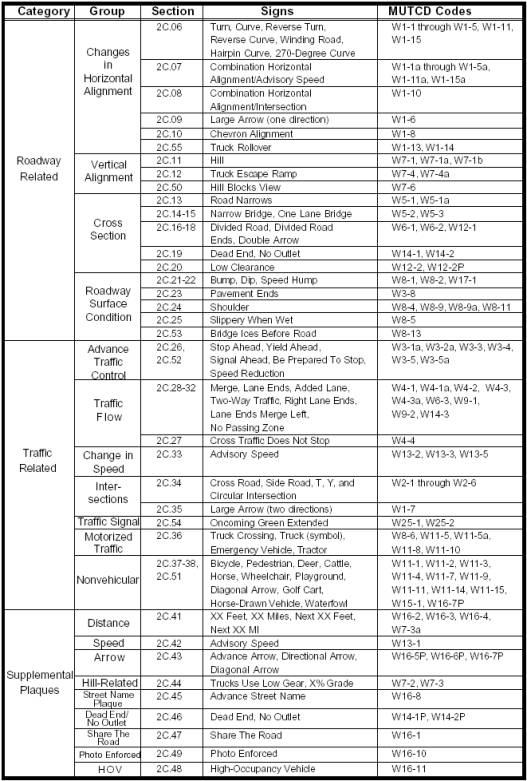
Key changes to Table 2C-1 include adding the following groups of warning signs: Traffic Signal, Nonvehicular, Photo Enforced, and HOV; adding the following Section reference of Warning Signs: 2C.55, 2C.50, 2C.53, 2C.26 and 2C.52; and corresponding additions and changes to the associated MUTCD codes.
112. Page 2C-3, Section 2C.04, Size of Warning Signs. Change:
Support:
Table 2C-2 is a listing of the sizes for warning signs.
Guidance:
The Conventional Road size should be used on conventional roads.
The Expressway and Freeway sizes should be used for higher-speed applications for increased recognition.
Option:
The minimum size may be used on low-speed roadways where the reduced legend size would be adequate.
Oversized signs and larger sizes may be used where speed, volume, or other factors result in conditions where greater visibility or emphasis would be desirable.
Standard:
The minimum size for supplemental
warning plaques shall be as shown in Table 2C-3.
to:
Support:
The “Standard Highway Signs” book prescribes design details for up to five different sizes depending on the type of traffic facility, including bikeways. Smaller sizes are designed to be used on bikeways and some other off-road applications. Larger sizes are designed for use on freeways and expressways, and can also be used to enhance road user safety and convenience on other facilities, especially on multilane divided highways and on undivided highways having five or more lanes of traffic and/or high speeds. The intermediate sizes are designed to be used on two-lane, three-lane, and four-lane highways that have low speeds and volumes.
Standard:
The sizes for warning signs shall be as shown in Table 2C-2.
Guidance:
The Conventional Road size should be used on conventional roads.
The Expressway and Freeway sizes should be used for higher-speed applications to provide larger signs for increased visibility and recognition.
Option:
The Minimum size may be used on low-speed roadways where the reduced legend size would be adequate for the warning or where physical conditions preclude the use of the other sizes.
Oversized signs and larger sizes may be used for those special applications where speed, volume, or other factors result in conditions where increased emphasis, improved recognition, or increased legibility would be desirable.
Standard:
The
minimum size for supplemental warning plaques shall be as shown in Table 2C-3.
Option:
Signs larger than those shown in Tables 2C-2 and 2C-3 may be used (see Section 2A.12).
113. Page 2C-4, Table 2C-2, Warning Sign Sizes. Replace select data in the table with the following: In Row 2, in Column 5, change: “900 x 900 (36 x 36)” to: “1200 x 1200 (48 x 48)” and in Column 7 replace: “1200 x 1200 (48 x 48)” with an em dash. In Row 6, in Columns 4 and 5, replace the em dashes with “1950 x 1200 (78 x 48)” in each column. In Row 7, in Column 2 change: “W7-4a” to: “W7-4a, b, c” and in Columns 4 and 5, replace the em dashes with “1950 x 1500 (78 x 60)” in each column. After Row 7, insert a new row: in Column 2 insert “W10-9, W10-10”; in Column 3 insert: “750 x 225 (30 x 9)”; and in Columns 4, 5, 6, and 7 insert em dashes. In Row 8, in Columns 4 and 5, replace the em dashes with “2100 x 600 (84 x 24)” in each column. In Row 9, in Column 2, change “W13” to: “W13, W25”. In Row 11, in Column 3, change: “450 (18) Dia.” to: “900 (36) Dia.”; in Column 4, replace the em dash with “1200 (48) Dia.”; in Column 6, change: “375 (15) Dia.” to: “750 (30) Dia.”; and in Column 7, change “600 (24) Dia.” to: “1200 (48) Dia.”
114. Page 2C-5, Section 2C.05, Placement of Warning Signs. Under Standard, change: “…Sections 2A.16 to 2A.21” to: “…Sections 2A.16 to 2A.22.”
115. Page 2C-6. Table 2C-4, Guidelines for Advance Placement of Warning Signs (Metric Units). Replace the table and associated notes with the following:
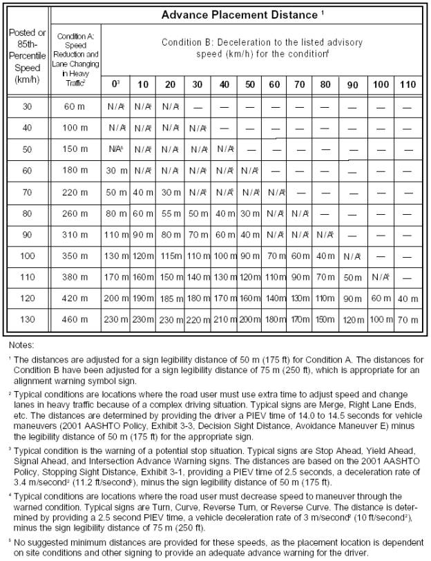
116. Page 2C-7, Table 2C-4, Guidelines for Advance Placement of Warning Signs (English Units). Replace the table and associated notes with the following:
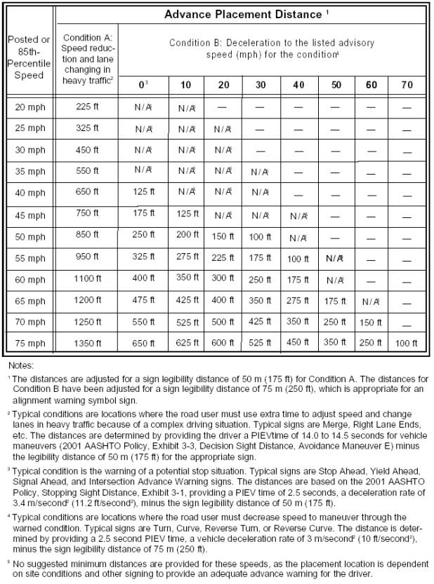
117. Page 2C-8, Section 2C.06, Horizontal
Alignment Signs (W1-1 through W1-5).
Change the Section title to: “Section 2C.06 Horizontal Alignment Signs (W1-1 through W1-5, W1-10, W1-11, W1-15).” Under the first Option, change:
The horizontal alignment Turn (W1-1), Curve (W1-2), Reverse Turn (W1-3), Reverse Curve (W1-4), or Winding Road (W1-5) signs may be used in advance of situations where the horizontal roadway alignment changes. A Large Arrow (W1-6) sign (see Section 2C.09) may be used on the outside of the turn or curve.
to:
The horizontal alignment Turn (W1-1), Curve (W1-2), Reverse Turn (W1-3), Reverse Curve (W1-4), or Winding Road (W1-5) signs (see Figure 2C-1) may be used in advance of situations where the horizontal roadway alignment changes. A One-Direction Large Arrow (W1-6) sign (see Figure 2C-1 and Section 2C.09) may be used on the outside of the turn or curve.
If the change in horizontal alignment is 135 degrees or more, the Hairpin Curve (W1-11) sign (see Figure 2C-1) may be used.
If the change in horizontal alignment is approximately 270 degrees, such as on a cloverleaf interchange ramp, the 270-degree Loop (W1-15) sign (see Figure 2C-1) may be used.
Under Guidance, add the following paragraph after the first paragraph:
When the Hairpin Curve sign or the 270-degree Loop sign is installed, either a One-Direction Large Arrow (W1-6) sign or Chevron Alignment (W1-8) signs should be installed on the outside of the turn or curve.
Under the second Option, change:
An Advisory Speed plaque (see Section 2C.42) may be used to indicate the speed for the change in horizontal alignment. The supplemental distance plaque NEXT XX KM (NEXT XX MILES) may be installed below the Winding Road sign where continuous roadway curves exist (see Section 2C.41). The combination Horizontal Alignment/Advisory Speed sign (see Section 2C.07) or combination Horizontal Alignment/Intersection sign (see Section 2C.08) may also be used.
to:
An Advisory Speed (W13-1) plaque (see Figure 2C-7 and Section 2C.42) may be used to indicate the speed for the change in horizontal alignment. The supplemental distance plaque NEXT XX KM (NEXT XX MILES) may be installed below the Winding Road sign where continuous roadway curves exist (see Section 2C.41). The combination Horizontal Alignment/Advisory Speed sign (see Section 2C.07), combination Horizontal Alignment/Intersection sign (see Section 2C.08), or the Curve Speed sign (see Section 2C.33) may also be used.
Under Standard, change: “When engineering judgment determines the need for a horizontal alignment sign, one of the W1-1 through W1-5 signs shall be used.” to: “When engineering judgment determines the need for a horizontal alignment sign, one of the W1-1 through W1-5, W1-10, W1-11 or W1-15 signs shall be used.” After the Standard, add the following:
Guidance:
The need for additional curve or turn warning and advisory speed reduction warning should be considered based on an engineering study or engineering judgment.
Option:
If the reduction in speed is 20 km/h (15 mph) or greater, a supplemental combination Horizontal Alignment/Advisory Speed sign or Curve Speed (W13-5) sign may be installed as near as practical to the point of curvature. If the reduction in speed is 40 km/h (25 mph) or greater, one or more additional Curve Speed signs may be installed along the curve.
118. Page 2C-8, Section 2C.07, Combination Horizontal Alignment/Advisory Speed Sign (W1-9). Change the Section title to: “Section 2C.07 Combination Horizontal Alignment/Advisory Speed Signs”; under Option, change:
The Turn (W1-1) sign or the Curve (W1-2) sign may be combined with the Advisory Speed (W13-1) plaque to create a combination Horizontal Alignment/Advisory Speed (W1-9) sign.
to:
The Turn (W1-1) sign may be combined with the Advisory Speed (W13-1) plaque (see Section 2C.42) to create a combination Turn/Advisory Speed (W1-1a) sign (see Figure 2C-1). Other Horizontal Alignment signs may also be combined with the Advisory Speed (W13-1) plaque to create a combination Horizontal Alignment/Advisory Speed sign.
Under Standard, change:
When used, the combination
Horizontal Alignment/Advisory Speed sign shall supplement other advance warning
signs and shall be installed at the beginning of the turn or curve. The minimum size of the W1-9 sign shall be
1200 x 1200 mm
(48 x 48 in) for high-speed facilities, and 900 x 900 mm (36 x 36 in) for low-speed facilities.
to:
When used, the combination Horizontal Alignment/Advisory Speed sign shall be installed as near as practical to the beginning of the turn or curve (see Figure 2C-2). The minimum size of the combination sign shall be 1200 x 1200 mm (48 x 48 in) for high-speed facilities, and 900 x 900 mm (36 x 36 in) for low-speed facilities. If a Horizontal Alignment warning sign with an Advisory Speed plaque is installed in advance of the turn or curve, the speeds shown on the Advisory Speed plaque and the combination sign shall be identical.
When the
recommended reduction in speed is 20 km/h (15 mph) or greater, the combination
Horizontal Alignment/Advisory Speed sign shall supplement other advance warning
signs.
Following the Standard, add:
Option:
When the recommended reduction in speed is less than 20 km/h (15 mph), instead of installing other advance warning signs, the combination Horizontal Alignment/Advisory Speed sign may be installed just before the point of curvature.
The Horizontal Alignment/Advisory Speed sign may also be used throughout the turn or curve.
119. Page 2C-9. Add a Figure number and title to this page of sign images: “Figure 2C-1 Horizontal Alignment Signs”; and add illustrations for the W1-1a and W1-2a Combination Horizontal Alignment/Advisory Speed signs, W1-11 Hairpin sign, the W1-13 and W1-13a Truck Tipping Over signs, and the W1-15 270-degree sign.”
120.
Page 2C-10, Table 2C-5, Horizontal Alignment Sign
Usage. In Row 3, Column3, change:
“Reverse Turn” to: “Reverse Curve”.
121. Page 2C-10, Section 2C.08, Combination Horizontal Alignment/Intersection Sign (W1-10). Under Option, change: “… to create a combination Horizontal Alignment/Intersection (W1-10) sign that depicts the condition …” to: “… to create a combination Horizontal Alignment/Intersection (W1-10) sign (see Figure 2C-1) that depicts the condition …”
122. Page 2C.10. Following Section 2C.08, add a new figure, numbered and titled: “Figure 2C-2. Example of Advisory Speed Signing for a Turn or Curve” illustrating the appropriate placement of advisory signing for a turn or curve.
123. Page 2C-10, 2C.09, One-Direction Large Arrow Sign (W1-6). Under Option, change: “A One-Direction Large Arrow (W1-6) sign may be used…” to: “A One-Direction Large Arrow (W1-6) sign (see Figure 2C-1) may be used…”
124. Page 2C-11, Section 2C.10, Chevron Alignment Sign (W1-8). Under the first Option, in the second sentence, change: “...on curves or to the Large Arrow...” to: “on curves or to the One-Direction Large Arrow”; under Standard, at the end of the first paragraph add: “No border shall be used on the Chevron Alignment sign”; under the second Option, change: “… to inform drivers of a change of horizontal alignment through the intersection.” to: “… to inform drivers of a change of horizontal alignment for through traffic.”
125. Page 2C-12, Section 2C.11 Hill Signs (W7-1, W7-1a, W7-1b). Under Guidance, in the first paragraph, change: “The Hill (W7-1) sign should be used…” to: “The Hill (W7-1) sign (see Figure 2C-3) should be used”; change: “The Hill sign and supplemental grade (W7-3) plaque (see Section 2C.45) used in combination…” to: “The Hill sign and supplemental grade (W7-3) plaque (see Section 2C.44) used in combination…”; in the fourth paragraph, in the second sentence, change: “On longer grades, the use of the distance (W7-3a) plaque …” to: “On longer grades, the use of the Hill sign with a distance (W7-3a) plaque…”
126. Page 2C-12 and 2C-14, Section 2C.12, Truck Escape Ramp Signs (W7-4 Series). Under Guidance, change: “Where applicable, truck escape (or runaway truck) ramp advance warning signs should be located…” to: “Where applicable, truck escape (or runaway truck) ramp advance warning signs (see Figure 2C-3) should be located…”
127. Page 2C-13. Add a Figure number and title to this page of sign images: “Figure 2C-3. Vertical Grade Signs”; and add an illustration for the HILL BLOCKS VIEW (W7-6) sign.
128. Page 2C-14, Section 2C.12, Truck Escape Ramp Signs (W7-4 Series). Under Standard, change: “When truck escape ramps are installed, one of the W7-4 series signs shall be used.” to: “When truck escape ramps are installed, at least one of the W7-4 series signs shall be used.”
129. Page 2C-14, Section 2C.13, ROAD NARROWS Sign (W5-1). Change the Section title to: “Section 2C.13 ROAD NARROWS Signs (W5-1, W5-1a)”. Under Guidance change: “A ROAD NARROWS (W5-1) sign should be used…” to: “A ROAD NARROWS (W5-1) sign (see Figure 2C-4) should be used…”; following the first paragraph of the Option, add new paragraph that reads: “The Road Narrows (W5-1a) symbol sign (see Figure 2C-4) may be used as an alternate to the word message ROAD NARROWS sign.”
130. Page 2C-14, Section 2C.14, NARROW BRIDGE Sign (W5-2). Under the Guidance, change "A NARROW BRIDGE (W5-2) sign should be used…” to “A NARROW BRIDGE (W5-2) sign (see Figure 2C-4) should be used…”;
131. Page 2C-15. Add a Figure number and title to this page of sign images: “Figure 2C-4. Miscellaneous Warning Signs”; and change the Narrow Bridge (W5-2a) symbol sign to the Narrow Road (W5-1a) symbol sign.
132. Page 2C-16, Section 2C.14, NARROW BRIDGE Sign (W5-2). Under Option, remove the second paragraph: “The Narrow Bridge (W5-2a) symbol sign may be used as an alternate to the word message NARROW BRIDGE sign.”
133. Page 2C-16, Section 2C.15, ONE LANE BRIDGE Sign (W5-3). Under Guidance, in the first paragraph, change: “A ONE LANE BRIDGE (W5-3) sign should be used…” to: “A ONE LANE BRIDGE (W5-3) sign (see Figure 2C-4) should be used…”; in Item C change: “Having a clear roadway width of 5.5 m (18 ft) or less, where the sight distance is limited on the approach to the structure.” to: “Having a clear roadway width of 5.5 m (18 ft) or less where the sight distance is limited on the approach to the structure.”
134. Page 2C-16, Section 2C.16, Divided Highway (Road) Sign (W6-1). Under Guidance, change: “A Divided Highway (W6-1) symbol sign should be used…” to: “A Divided Highway (W6-1) symbol sign (see Figure 2C-4) should be used…”; under Option, change: “The word message DIVIDED HIGHWAY (W6-1a) or DIVIDED ROAD (W6-1b) sign may be used…” to: “The word message DIVIDED HIGHWAY (W6-1a) or DIVIDED ROAD (W6-1b) sign (see Figure 2C-4) may be used…”
135. Page 2C-17, Section 2C.17, Divided Highway (Road) Ends Sign (W6-2). Under Guidance, change: “A Divided Highway Ends (W6-2) symbol sign should be used at the end of a section of physically divided highway (not an intersection or junction) as a warning of two-way traffic ahead.” to: “A Divided Highway Ends (W6-2) symbol sign (see Figure 2C-4) should be used in advance of the end of a section of physically divided highway (not an intersection or junction) as a warning of two-way traffic ahead.”; under Option, in the first paragraph, change: “The TWO-WAY TRAFFIC (W6-3) sign (see Section 2C.31) may be used…” to: “The Two-Way Traffic (W6-3) symbol sign (see Section 2C.31) may be used…”; in the second paragraph, change: “The word message DIVIDED HIGHWAY ENDS (W6-2a) or DIVIDED ROAD ENDS (W6-2b) sign may be used as an alternate to the symbol sign.” to: “The word message DIVIDED HIGHWAY ENDS (W6-2a) or DIVIDED ROAD ENDS (W6-2b) sign (see Figure 2C-4) may be used as an alternate to the symbol sign.”
136. Page 2C-17, Section 2C.18, Double Arrow Sign (W12-1). Under Option, change: “The Double Arrow (W12-1) sign may be used to advise road users…” to: “The Double Arrow (W12-1) sign (see Figure 2C-4) may be used to advise road users…”
137. Pages 2C-17 and 2C-18, Section 2C.19, DEAD END/NO OUTLET Signs (W14-1, W14-2). Under Option, in the first paragraph, change: “The DEAD END (W14-1) sign may be used …” to: “The DEAD END (W14-1) sign (see Figure 2C-4) may be used…”; in the second paragraph, change: “The DEAD END or NO OUTLET plaques (see Section 2C.46) may be used in combination with the Street Name (D3) sign…” to: “The DEAD END or NO OUTLET plaques (see Section 2C.46) may be used in combination with the Street Name (D3-1) sign…”; Under Standard, change: “When the W14-1 or W14-2 sign is used, the sign shall be posted at the entry point…” to: “When the W14-1 or W14-2 sign is used, the sign shall be posted as near as practical to the entry point…”
138. Page 2C-18, Section 2C.20, Low Clearance Signs (W12-2 and W12-2P). Under Standard, change: “The Low Clearance (W12-2) sign shall be used …” to: “The Low Clearance (W12-2) sign (see Figure 2C-4) shall be used …”; under Guidance in the second paragraph, change: “Where the clearance is less than the legal limit, a sign to that effect should be placed at the nearest intersecting road or wide point in the road at which a vehicle can detour or turn around.” to: “Where the clearance is less than the legal maximum vehicle height, the W12-2 sign with a supplemental distance plaque should be placed at the nearest intersecting road or wide point in the road at which a vehicle can detour or turn around.”; under Option, in the second sentence, change: “… a rectangular shape (W12-2P) with the appropriate legend.” to: “… a rectangular shape (W12-2P) with the appropriate legend (see Figure 2C-4).”
139. Page 2C-19. Add a Figure number and title to this page of sign images: “Figure 2C-5. Roadway Condition and Advance Traffic Control Signs”; and add the W8-13 BRIDGE ICES BEFORE ROAD sign and the W3-4 BE PREPARED TO STOP sign.
140. Page 2C-20, Section 2C.21, BUMP and DIP Signs (W8-1, W8-2). Under the first Guidance, change: “BUMP (W8-1) and DIP (W8-2) signs should be used …” to: “BUMP (W8-1) and DIP (W8-2) signs (see Figure 2C-5) should be used …”; Under Standard, change: “The DIP sign shall not be used at a short stretch of depressed alignment that may momentarily hide a vehicle.” to: “The DIP sign shall not be used at a short stretch of depressed alignment that might momentarily hide a vehicle.”; Under the second Guidance, change: “A short stretch of depressed alignment that may momentarily hide a vehicle should be treated as a no-passing zone (see Section 3B.02).” to: “A short stretch of depressed alignment that might momentarily hide a vehicle should be treated as a no-passing zone when centerline striping is provided on a two-lane or three-lane road (see Section 3B.02).”
141. Page 2C-20, Section 2C.22, SPEED HUMP Sign (W17-1). Under Guidance, change: “The SPEED HUMP (W17-1) sign should be used…” to: “The SPEED HUMP (W17-1) sign (see Figure 2C-5) should be used…”; after the first paragraph of the Option, add a new paragraph that reads: “The legend SPEED BUMP may be used instead of the legend SPEED HUMP on the W17-1 sign.”
142. Page 2C-20, Section 2C-23, PAVEMENT ENDS Sign (W8-3). Under Guidance, change: “A PAVEMENT ENDS (W8-3) word message sign should be used…” to: “A PAVEMENT ENDS (W8-3) word message sign (see Figure 2C-5) should be used…”
143. Page 2C-21, Section 2C.24, Shoulder Signs (W8-4, W8-9, W8-9a, and W8-11). Change the Section title to: “Section 2C.24 Shoulder and UNEVEN LANES Signs (W8-4, W8-9, W8-9a, and W8-11)”; under Support, change: “The signs discussed in this Section are appropriate for use in temporary traffic control zones (see Part 6).” to: “The signs discussed in this Section are also appropriate for use in temporary traffic control zones (see Section 6F.41).”; under Option, in the first paragraph, change: “The SOFT SHOULDER (W8-4) word message sign may be used…” to: “The SOFT SHOULDER (W8-4) sign (see Figure 2C-5) may be used…”; in the second paragraph, change: “The LOW SHOULDER (W8-9) word message sign may be used…” to: “The LOW SHOULDER (W8-9) sign (see Figure 2C-5) may be used…”; following Option, add a new Standard: “The SHOULDER DROP-OFF (W8-9a) sign (see Figure 2C-5) shall be used when a shoulder drop-off, adjacent to the travel lane, exceeds 75 mm (3 in) in depth and is not protected by portable barriers.”; under Guidance, remove the first paragraph: “The SHOULDER DROP-OFF (W8-9a) sign should be used during construction and maintenance when a shoulder drop-off exceeds 75 mm (3 in) in height.”; in the second paragraph, change: “The UNEVEN LANES (W8-11) word message sign should be used…” to: “The UNEVEN LANES (W8-11) sign (see Figure 2C-5) should be used…”
144. Page 2C-22, Section 2C.25, Slippery When Wet Sign (W8-5). Under the Option, change: “The Slippery When Wet (W8-5) sign may be used to warn that a slippery condition may exist.” to: “The Slippery When Wet (W8-5) sign (see Figure 2C-5) may be used to warn that a slippery condition might exist.”
145. Page 2C-22, Section 2C.26, Advance Traffic Control Signs (W3-1, W3-2, W3-3, W3-4). Change the Section title to: “Section 2C.26 Advance Traffic Control Signs (W3-1a, W3-2a, W3-3, W3-4)”; under Standard, in the first sentence, change: “The Advance Traffic Control symbol signs include…” to: “The Advance Traffic Control symbol signs (see Figure 2C-5) include…”
146. Page 2C-23, Section 2C.26, Advance Traffic Control Signs (W3-1a, W3-2a, W3-3, W3-4). Under Option, in the first paragraph, change: “A warning beacon may be used with a Signal Ahead (W3-3) sign.” to: “A warning beacon may be used with an Advance Traffic Control sign.”; in the second paragraph, change: “A BE PREPARED TO STOP (W3-4) sign may be used to warn of stopped traffic caused by traffic control signals or in areas that regularly experience traffic congestion.” to: “A BE PREPARED TO STOP (W3-4) sign (see Figure 2C-5) may be used to warn of stopped traffic caused by a traffic control signal or in advance of a section of roadway that regularly experiences traffic congestion.”; under Standard, change: “When a BE PREPARED TO STOP sign is used in advance of traffic signals, it shall be used in addition to a Signal Ahead sign.” to: “When a BE PREPARED TO STOP sign is used in advance of a traffic control signal, it shall be used in addition to a Signal Ahead sign.”; under Option, change: “The BE PREPARED TO STOP sign may be supplemented with beacons.” to: “The BE PREPARED TO STOP sign may be supplemented with a warning beacon.”; under Guidance, change: “When the beacon is interconnected with a traffic control signal…” to: “When the warning beacon is interconnected with a traffic control signal…”
147. Page 2C-23, Section 2C.27, CROSS TRAFFIC DOES NOT STOP Plaque (W4-4). Change Section title to: “Section 2C.27 CROSS TRAFFIC DOES NOT STOP Plaque (W4-4)”; replace the Section text in its entirety with the following:
Option:
The CROSS TRAFFIC DOES NOT STOP (W4-4) plaque (see Figure 2C-9) may be used in combination with a STOP sign when engineering judgment indicates that drivers frequently misinterpret the intersection as a multi-way stop condition.
Standard:
If the W4-4 plaque is used, it shall be installed below the STOP sign.
148. Page 2C-24. Add a Figure number and title to this page of sign images: “Figure 2C-6. Merging and Passing Signs” and add the W4-1a Entering Roadway Merge sign, the W4-2 Lane Ends symbol sign, and the W4-3a Added Lane sign. Remove the arrow from the W4-4P CROSS TRAFFIC DOES NOT STOP sign, renumber it as W4-4, and move it to Figure on existing page 2C-29.
149. Page 2C-24, Section 2C.28, Merge Sign (W4-1). Change the Section title to: “Section 2C.28 Merge Signs (W4-1, W4-1a)”; under Option, in the first paragraph, change: “A Merge (W4-1) sign may be used…” to: “A Merge (W4-1) sign (see Figure 2C-6) may be used…”; under Guidance, following the second paragraph, add a new paragraph:
When a Merge sign is to be installed on an entering roadway that curves before merging with the major roadway, such as a ramp with a curving horizontal alignment as it approaches the major roadway, the Entering Roadway Merge (W4-1a) sign (see Figure 2C-6) should be used to better portray the actual geometric conditions to road users on the entering roadway.
150. Page 2C-25, Section 2C.28, Merge Sign (W4-1). Under Guidance, in the second paragraph, change: “The Merge sign should not be used in place of a Lane Ends (W4-2) sign…” to: “The Merge sign should not be used in place of a Lane Ends sign…”
151. Page 2C-25, Section 2C.29, Added Lane Sign (W4-3). Change the section title to: “Section 2C. 29 Added Lane Signs (W4-3, W4-3a)”; under Guidance, change: “The Added Lane (W4-3) sign should be installed…” to: “The Added Lane (W4-3) sign (see Figure 2C-6) should be installed”; and at the end of Guidance add a new paragraph that reads:
When an Added Lane sign is to be installed on a roadway that curves before converging with another roadway that has a tangent alignment at the point of convergence, the Entering Roadway Added Lane (W4-3a) sign (see Figure 2C-6) should be used to better portray the actual geometric conditions to road users on the curving roadway.
152. Page 2C-25, Section 2C.30, Lane Ends Signs (W9-1, W9-2). Change Section title to: “Section 2C.30 Lane Ends Signs (W4-2, W9-1, W9-2).” Under the first Guidance, change: “The LANE ENDS MERGE LEFT (RIGHT) sign (W9-2) should be used to warn of the reduction in the number of traffic lanes in the direction of travel on a multilane highway.” to: “The LANE ENDS MERGE LEFT (RIGHT) (W9-2) word sign, or the Lane Reduction (W4-2) symbol sign, should be used to warn of the reduction in the number of traffic lanes in the direction of travel on a multilane highway (see Figure 2C-6)”; under Option, add a new first paragraph: “The number of lanes depicted at the top and the bottom of the Lane Reduction (W4-2) sign may be modified to represent the actual road lane configuration”; and in the existing first paragraph, (new second paragraph) change:
The RIGHT (LEFT) LANE ENDS (W9-1) sign may be used in advance of the Lane Ends (W4-2) sign or the LANE ENDS MERGE LEFT (RIGHT) (W9-2) sign as additional warning or to emphasize that the traffic lane is ending and that a merging maneuver will be required.
to:
The RIGHT (LEFT) LANE ENDS (W9-1) word sign (see Figure 2C-6) may be used in advance of the Lane Reduction (W4-2) symbol sign or the LANE ENDS MERGE LEFT (RIGHT) (W9-2) word sign as additional warning or to emphasize that the traffic lane is ending and that a merging maneuver will be required.
Under the second Guidance, in the first paragraph, change: “Where an extra lane has been provided for slower moving traffic (see Section 2B.27), a Lane Ends sign should be installed in advance of the end of the extra lane.” to: “Where an extra lane has been provided for slower moving traffic (see Section 2B.27), a Lane Ends word sign or a Lane Reduction (W4-2) symbol sign should be installed in advance of the end of the extra lane.”
153. Page 2C-26, Section 2C.31, Two-Way Traffic Sign (W6-3). Under Guidance, change: “A Two-Way Traffic (W6-3) sign should be used…” to: “A Two-Way Traffic (W6-3) sign (see Figure 2C-6) should be used…”
154.
Page 2C-26, Section 2C.32, NO PASSING ZONE Sign
(W14-3). Under Standard, in the
first sentence, change: “The NO PASSING ZONE (W14-3) sign shall be a
pennant-shaped isosceles triangle…” to: “The NO PASSING ZONE (W14-3) sign (see
Figure 2C-6) shall be a pennant-shaped isosceles triangle…”
155. Page 2C-26, Section 2C.33, Advisory Exit, Ramp, and Curve Speed Signs (W13-2, W13-3, W13-5). Under Standard, in the second paragraph, change: “The Exit Speed (W13-2), Ramp Speed (W13-3), or Curve Speed (W13-5) signs shall be used…” to: “The advisory Exit Speed (W13-2), Ramp Speed (W13-3), or Curve Speed (W13-5) signs (see Figure 2C-7) shall be used”; also consolidate paragraphs one and two of the Standard; under Guidance, in the first paragraph, change: “The Exit Speed sign should be used along the deceleration lane and the Ramp Speed sign should be used along the actual ramp since in some cases the ramp speed may be different from the deceleration exit speed.” to: “The Exit Speed sign should be used along the deceleration lane and one or more Ramp Speed signs should be used along the actual ramp since in some cases the ramp speed may be different from the deceleration exit speed (see Figure 2C-8).”
156. Page 2C.27. Add a Figure number and title to this page of sign images: “Figure 2C-7. Advisory Speed and Speed Reduction Signs”; remove the METRIC plaque and add a black circle around the speed value on all metric speed advisory speed signs; add the new diamond shaped symbol (W3-5) and word (W3-5a) Speed Reduction signs in both metric and English units.
157. Page 2C-28, Section 2C.33, Advisory Exit, Ramp, and Curve Speed Signs (W13-2, W13-3, W13-5). Under Option, in the second paragraph, change:
A Curve Speed sign may be used beyond the beginning of a curve following a Horizontal Alignment and Advisory Speed sign combination where the recommended speed changes because of a change in curvature or when there is a need to remind road users of the recommended speed.
to:
A Curve Speed sign may be used at and beyond the beginning of a curve following a Horizontal Alignment and Advisory Speed sign combination, or when there is a need to remind road users of the recommended speed, or where the recommended speed changes because of a change in curvature (see Section 2C.06).
Following the second paragraph of the Option, add a new paragraph:
The 85th-percentile speed, which is equivalent to the 16-degree ball-bank indication or an 88 mm/second (0.28 ft/second) reading on an accelerometer, along the ramp or curve may be used to determine the recommended speed as it is the speed at which most road users’ judgment recognizes incipient instability along a ramp or curve.
158. Following Section 2C.33, add a new Figure numbered and titled: “Figure 2C-8. Example of Advisory Speed Signing for an Exit Ramp” that depicts a freeway exit ramp with additional Advisory Speed Ramp (W13-3) installed along the ramp.
159. Page 2C-28, Section 2C.34, Intersection Warning Signs (W2-1 through W2-6). Under Option, in the first paragraph, change:
A Cross Road (W2-1), Side Road (W2-2 or W2-3), T-Symbol (W2-4), or Y-Symbol (W2-5) sign may be used on a roadway, street, or shared-use path in advance of an intersection to indicate the presence of an intersection and the possibility of turning or entering traffic. The Circular Intersection (W2-6) sign accompanied by an educational word message plaque may be installed in advance of a circular intersection.
to:
A Cross Road (W2-1) symbol, Side Road (W2-2 or W2-3) symbol, T-Symbol (W2-4), or Y-Symbol (W2-5) sign (see Figure 2C-9) may be used in advance of an intersection to indicate the presence of an intersection and the possibility of turning or entering traffic. The Circular Intersection (W2-6) symbol sign accompanied by an educational word message plaque may be installed in advance of a circular intersection.
Under Option, in the third paragraph, change: “An advance street name plaque (see Section 2C.45) may be installed below an Intersection sign.” to: “An advance street name plaque (see Section 2C.45) may be installed below an Intersection warning sign.”; under the Guidance, in the first paragraph, change: “The Intersection sign should illustrate and depict the general configuration of the intersecting roadway, such as cross road, side road, T-intersection, Y-intersection, or curvilinear alignment.” to: “The Intersection warning sign should illustrate and depict the general configuration of the intersecting roadway, such as cross road, side road, T-intersection, or Y-intersection.”; in the second paragraph, change:
Intersection signs should not be used on approaches controlled by STOP signs, YIELD signs, signals, or where Junction signing (see Sections 2D.13 and 2D.28) or advance route turn assembly signs (see Section 2D.29) are present.
to:
Intersection Warning signs, other than the Circular Intersection Warning symbol (W2-6) sign, should not be used on approaches controlled by STOP signs, YIELD signs, signals, or where Junction signing (see Sections 2D.13 and 2D.28) or advance route turn assembly signs (see Section 2D.29) are present.
Under the Guidance, following the third paragraph add a new paragraph: “The Circular Intersection Warning symbol (W2-6) sign should be installed on the approach to a YIELD sign controlled roundabout intersection.”
160.
Page 2C-29, Section 2C.35, Two-Direction Large Arrow
Sign (W1-7). Under Standard, in the
first paragraph, change: “The Two-Direction Large Arrow (W1-7) sign shall be a
horizontal rectangle.” to: “The Two-Direction Large Arrow (W1-7) sign (see
Figure 2C-9) shall be a horizontal rectangle.”
161.
Page 2C-29. Add
a Figure number and title to this page of sign images: “Figure 2C-9. Intersection Warning Signs”; change the
Circular Intersection (W2-6) to three curved arrows instead of the circle; add
the CAUTION ONCOMING GREEN EXTENDED (W25-1) sign; add the CAUTION ONCOMING
GREEN MAY BE EXTENDED (W25-2) sign; add the CROSS TRAFFIC DOES NOT STOP (W4-4)
sign without an arrow.
162.
Page 2C-29, Section 2C.35, Two-Direction Large Arrow
Sign (W1-7). Under Standard, in the
first paragraph, change: “The Two-Direction Large Arrow (W1-7) sign shall …”
to: “The Two-Direction Large Arrow (W1-7) sign (see Figure 2C-9) shall …”
163. Page 2C-30, Section 2C.36, Motorized Traffic Signs (W8-6, W11-5, W11-8, W11-10). Change the Section title to: “Section 2C.36 Motorized Traffic Signs (W8-6, W11-5, W11-5a, W11-8, W11-10, W11-10a, W11-12)” Under the first Option, change:
Motorized Traffic (W8-6, W11-5, W11-8, W11-10 or W11-10a, W11-12) signs may be used to alert road users to locations where unexpected entries into the roadway by trucks, farm vehicles, emergency vehicles, or other vehicles might occur.
to:
Motorized Traffic (W8-6, W11-5, W11-5a, W11-8, W11-10 or W11-10a) signs (see Figure 2C-10) may be used to alert road users to locations where unexpected entries into the roadway by trucks, farm vehicles, emergency vehicles, or other vehicles might occur. The TRUCK CROSSING (W8-6) word message sign may be used as an alternate to the Truck Crossing symbol (W11-10) sign.
Under the second Option, change:
Supplemental plaques (see Section 2C.39) with the legend AHEAD, XX METERS (XX FEET), or NEXT XX KILOMETERS (NEXT XX MILES) may be mounted below Motorized Traffic signs to provide advance notice to road users of unexpected entries.
to:
Supplemental plaques (see Section 2C.39) with legends such as AHEAD, XX METERS (XX FEET), NEXT XX KILOMETERS (NEXT XX MILES), or SHARE THE ROAD may be mounted below Motorized Traffic signs to provide advance notice to road users of unexpected entries.
Under Standard, change: “The Emergency Vehicle (W11-8) sign with the EMERGENCY SIGNAL AHEAD (W11-12P) supplemental plaque shall be placed in advance of all emergency-vehicle traffic control signals (see Chapter 4F).” to: “The Emergency Vehicle (W11-8) sign with the EMERGENCY SIGNAL AHEAD (W11-12) supplemental plaque (see Figure 2C-10) shall be placed in advance of all emergency-vehicle traffic control signals (see Chapter 4F).”
164. Page 2C-30, Section 2C.37, Crossing Signs (W11-1, W11-2, W11-3, W11-4, W16-7P). Change the Section title to: “Section 2C.37 Nonvehicular Signs (W11-1, W11-2, W11-3, W11-4, W11-11, W11-14, , W11-14a, W11-15)”; under Option, change: “Crossing (W11-1 through W11-4) signs may be used to alert road users to locations where unexpected entries into the roadway by pedestrians, bicyclists, animals, and other crossing activities might occur.” to: “Nonvehicular signs (see Figure 2C-10) may be used to alert road users in advance of locations where unexpected entries into the roadway or shared use of the roadway by pedestrians, bicyclists, golf carts, animals, horse-drawn vehicles, and other crossing activities might occur.”
165. Page 2C-31. Add a Figure number and title to this page of sign images: “Figure 2C-10. Motorized Traffic and Nonvehicular Signs”; add the Tractor W11-5a sign, the Golf Cart (W11-11) sign, the SHARE THE ROAD (W16-1) sign, the Playground (W15-1) sign, the Horse and Buggy (W11-14) sign, the Horse and Carriage (W11-14a) sign, the Waterfowl (W11-15), the Dump Truck (W11-10a) sign; change the number of the EMERGENCY SIGNAL AHEAD sign from “W11-12P” to “W11-12”.
166. Page 2C-32, Section 2C.37, Crossing Signs (W11-1, W11-2, W11-3, W11-4, W16-7P). Under the first Option, change: “Crossing signs may be supplemented with supplemental plaques (see Section 2C.39) with the legend AHEAD, XX METERS (XX FEET), or NEXT XX KILOMETERS (NEXT XX MILES) to provide advance notice to road users of crossing activity.” to: “When used in advance of a crossing, Nonvehicular warning signs may be supplemented with supplemental plaques (see Section 2C.39) with the legend AHEAD, XX METERS (XX FEET), or NEXT XX KILOMETERS (NEXT XX MILES) to provide advance notice to road users of crossing activity.”; under Standard, in the first sentence, change:
Crossing signs shall be used adjacent to the crossing location. If the crossing location is not delineated by crosswalk pavement markings, the Crossing sign shall be supplemented with a diagonal downward pointing arrow plaque (W16-7P) showing the location of the crossing. If the crossing location is delineated by crosswalk pavement markings, the diagonal downward pointing arrow plaque shall not be required.
to:
When used at the crossing, Nonvehicular warning signs shall be supplemented with a diagonal downward pointing arrow (W16-7) plaque (see Figure 2C-10) showing the location of the crossing.
Under the second Option, in the first paragraph, change: “The crossing location may be defined with pavement markings...” to: “The crossing location may be defined with crosswalk markings…”; in the second paragraph, change: “Pedestrian, Bicycle, School Advance Crossing, and School Crossing signs may have a fluorescent yellow-green background with a black legend and border.” to: “Pedestrian, Bicycle, School Advance Crossing, and School Crossing signs and their related supplemental plaques may have a fluorescent yellow-green background with a black legend and border.”; under Guidance, in the second paragraph, change: “Crossing signs should be used only at locations where the crossing activity is unexpected or at locations not readily apparent.” to: “Nonvehicular signs should be used only at locations where the crossing activity is unexpected or at locations not readily apparent.”
167. Page 2C-32, Section 2C.38, Playground Sign (W15-1). Under Option, change: “The Playground (W15-1) sign may be used…” to: “The Playground (W15-1) sign (see Figure 2C-10) may be used…”
168. Page 2C-33. Add a figure number and title to this page of sign images: “Figure 2C-11. Supplemental Warning Plaques”; remove the Playground (W15-1) plaque and the SHARE THE ROAD (W16-1) plaque; add a two line example of the street name (W16-8) plaque with arrows, the PHOTO ENFORCED (W16-10) plaque, the HOV 2+ (W16-11) plaque; change the font of the W7-3a and W7-3b plaques to be identical to the font on the W7-3 plaque; add a border to the W16-8 plaque.
169. Page
2C-34, Section 2C.38, Playground Sign (W15-1).
Under Guidance, in the
second line, change: “Crossing” to: “Nonvehicular”.
170.
Page 2C-34,
Section 2C.41, Distance Plaques (W16-2, W16-3, W16-4, W7-3a).
Change the Section title to: “Section 2C.41 Distance Plaques (W16-2 series, W16-3
series, W16-4, W7-3a)”; Under
Option, in the first paragraph, change: “The Distance Ahead (W16-2 and W16-3)
plaques may be used…” to: “The Distance Ahead (W16-2 series and W16-3 series)
plaques (see Figure 2C-11) may be used…”; and in the second paragraph, change:
“The Next Distance (W16-4 and W7-3a) plaques may be used…” to: “The Next
Distance (W16-4 and W7-3a) plaques (see Figure 2C-11) may be used…”
171. Page 2C-35, Section 2C.42, Advisory Speed Plaque (W13-1). Under Option, change: “The Advisory Speed (W13-1) plaque may be used to indicate the recommended speed for a condition.” to: “The Advisory Speed (W13-1) plaque (see Figure 2C-7) may be used to supplement any warning sign to indicate the recommended speed for a condition.”; under Standard, add a new first paragraph: “The Advisory Speed plaque shall be used where an engineering study indicates a need to advise road users of the recommended speed for a condition.”; in the existing first paragraph (new second paragraph) change: “The Advisory Speed plaque shall carry the message XX km/h (XX M.P.H). The speed shown shall be a multiple of 10 km/h (5 mph).” to: “If used, the Advisory Speed plaque shall carry the message XX km/h (XX M.P.H). The speed shown shall be a multiple of 10 km/h (5 mph).”; following the Guidance, add an Option:
The 85th-percentile speed, which is equivalent to the 16-degree ball-bank indication or an 88 mm/second (0.28 ft/second) reading on an accelerometer, along the ramp or curve may be used to determine the recommended speed as it is the speed at which most road users’ judgment recognizes incipient instability along a ramp or curve.
172. Page 2C-35, Section 2C.43, Supplemental Arrow Plaques (W16-5P, W16-6P). Change the Section
title to: “Section 2C.43 Supplemental Arrow Plaques (W16-5, W16-6,
W16-7)”; under Guidance, in the last line, change: “…Supplemental Arrow plaque (W16-5P,
W16-6P) should…” to: “Supplemental
Arrow plaque (W16-5P, W16-6P, W16-7) (see Figure 2C.10)
should…”; under Standard, change: “Supplemental Arrow plaques shall have the
same legend design as the Advance Turn and
Direction Arrow markers …” to: “Supplemental
Arrow plaques (see Figure 2C-10) shall have the same legend design as the
Advance Turn Arrow and Direction Arrow auxiliary signs…”
173. Page 2C-35, Section 2C.44, Hill-Related Plaques (W7-2 and W7-3). Change the Section title to: “Section 2C.44 Hill-Related Plaques (W7-2 Series, W7-3 Series)”; under Guidance, change: “Hill-Related (W7-2 series, W7-3 series) plaques (or other appropriate legends) and larger signs should be used for emphasis or where special hill characteristics exist.” to: “Hill-Related (W7-2 series, W7-3 series) plaques (see Figure 2C-11) or other appropriate legends and larger signs should be used for emphasis or where special hill characteristics exist.”
174. Page 2C-36, Section 2C.45, Advance Street Name Plaque (W16-8). Under Option, change: “An Advance Street Name (W16-8) plaque may be used…” to: “An Advance Street Name (W16-8) plaque (see Figure 2C-11) may be used…”
175. Page
2C-36, Section 2C.46, DEAD END/NO OUTLET
Plaques (W14-1P, W14-2P).
Under Option, change: “DEAD END (W14-1P) or NO OUTLET(W14-2P)
plaques may be used in combination
Street Name (D3) signs (see Section 2D.38) at intersections instead of or in
addition to the W14-1 or W14-2 signs.” to: “DEAD
END (W14-1P) or NO OUTLET(W14-2P) plaques (see Figure 2C-11) may be used in combination Street Name (D3-1) signs
(see Section 2D.38) to warn turning traffic that the cross street ends in the
direction indicated by the arrow.”; following
the first paragraph, add a new paragraph: “At locations where the cross street
does not have a name, DEAD END or NO OUTLET plaques may be used alone in place
of a street name sign."; remove the
Standard in its entirety.
176. Page 2C-36, Section 2C.47, SHARE THE ROAD Plaque (W16-1). Under Option, change:
In situations where there is a need to warn drivers to watch for other slower forms of transportation traveling along the highway, such as bicycles, golf carts, or farm machinery, a SHARE THE ROAD (W16-1) plaque may be used.
to:
In situations where there is a need to warn drivers to watch for other slower forms of transportation traveling along the highway, such as bicycles, golf carts, horse-drawn vehicles, or farm machinery, a SHARE THE ROAD (W16-1) plaque (see Figure 2C-10) may be used.
177. Page 2C-36. Following Section 2C.47, add a new Section numbered and titled: “2C.48 High Occupancy Vehicle (HOV) Plaque (W16-11)”. The new section reads:
Option:
In situations where there is a need to warn drivers in an HOV lane of a specific condition, a HOV (W16-11) plaque (see Figure 2C-11) may be used. The HOV plaque may be used to differentiate a warning sign specific for HOV lanes when the sign is also visible to traffic on the adjoining general purpose roadway. Among the warning signs that may be possible applications of the HOV plaque are the Advisory Speed, Advisory Exit Speed, Added Lane, and Merge signs.
The diamond symbol may be used instead of the word message HOV on the W16-11 plaque. When appropriate, the words LANE or ONLY may be used on this plaque.
Then, add a new Section numbered and titled: “Section 2C.49 PHOTO ENFORCED Plaque (W16-10)”. The new Section reads:
Option:
A PHOTO ENFORCED (W16-10) plaque (see Figure 2C-11) may be mounted below a warning sign to advise road users that the regulations associated with the condition being warned about (such as a traffic signal or a toll plaza) are being enforced by photographic equipment.
Standard:
If used below a warning sign, the
PHOTO ENFORCED plaque shall be a rectangle with a black legend and border on a
yellow background.
Then, add a new Section numbered and titled: “Section 2C.50 HILL BLOCKS VIEW Sign (W7-6)”. The new section reads:
Option:
A HILL BLOCKS VIEW (W7-6) sign (see Figure 2C-3) may be used in advance of a crest vertical curve to advise road users to reduce speed as they approach and traverse the hill as only limited stopping sight distance is available.
Guidance:
When a HILL BLOCKS VIEW sign is used, it should be supplemented by an Advisory Speed (W13-1) plaque indicating the recommended speed for traveling over the hillcrest based on available stopping sight distance.
Then, add a new Section numbered and titled: “Section 2C.51 Speed Reduction Signs (W3-5, W3-5a)”. The new Section reads:
Guidance:
A Speed Reduction (W3-5 or W3-5a) sign (see Figure 2C-7) should be used to inform road users of a reduced speed zone when engineering judgment indicates the need for advance notice to comply with the posted speed limit ahead.
Standard:
If used, Speed Reduction signs shall be followed by a Speed Limit (R2-1) sign installed at the beginning of the zone where the speed limit applies.
The speed limit displayed on the Speed Reduction sign shall be identical to the speed limit displayed on the subsequent Speed Limit sign.
Then, add a new Section numbered and titled: “Section 2C.52 BRIDGE ICES BEFORE ROAD Sign (W8-13)”. The new Section reads:
Option:
A BRIDGE ICES BEFORE ROAD (W8-13) sign (see Figure 2C-5) may be used in advance of bridges to advise bridge users of winter weather conditions.
Guidance:
The BRIDGE ICES BEFORE ROAD sign should be removed or covered during seasons of the year when its message is not relevant.
Then, add a new Section numbered and titled: “Section 2C.53 Traffic Signal Signs (W25-1, W25-2)”. The new Section reads:
Standard:
Unless a separate left-turn signal
face is provided and is operated as described in Section 4D.06, if the
possibility exists that a CIRCULAR YELLOW signal indication could be displayed
to an approach from which drivers are turning left permissively without the
simultaneous display of a CIRCULAR YELLOW signal indication to the opposing
approach (see Section 4D.05), either a W25-1 or a W25-2 sign (see Figure 2C-9)
shall be installed near the left-most signal head. If the operation described in the previous sentence occurs
regularly, the CAUTION ONCOMING GREEN EXTENDED (W25-1) sign shall be used; if
the operation occurs only occasionally, the CAUTION ONCOMING GREEN MAY BE
EXTENDED (W25-2) sign shall be used.
Then, add a new Section numbered and titled: “Section 2C.54 Truck Rollover Warning Signs (W1-13, W1-13a)”. The new Section reads:
Option:
A Truck Rollover Warning (W1-13) sign or Combination Truck Rollover/Advisory Speed (W1-13a) sign (see Figure 2C-1) may be used to warn drivers of vehicles with a high center of gravity, such as trucks, tankers, and recreational vehicles, of a curve or turn having geometric conditions that are prone to cause such vehicles to lose control and overturn.
Standard:
When the Truck Rollover Warning (W1-13) sign is used, it shall be accompanied by an Advisory Speed Plaque (W13-1) indicating the recommended speed for vehicles with a higher center of gravity.
Option:
The Truck Rollover Warning or Combination Truck Rollover/Advisory Speed sign may be displayed either as a static sign, a static sign supplemented by a flashing warning beacon, or as a changeable message sign activated by the detection of an approaching vehicle with a high center of gravity that is traveling in excess of the recommended speed for the condition.
178. Page 2D-1, Section 2D.03, Color, Retroreflection, and Illumination. Following Standard, insert new paragraphs:
Support:
Color coding is sometimes used to help road users distinguish between multiple potentially confusing destinations. Examples of valuable uses of color coding include guide signs for roadways approaching or inside an airport property with multiple terminals serving multiple airlines, and wayfinding signs for various traffic generator destinations within a community or area.
Standard:
Different color sign backgrounds shall not be used to provide color coding of destinations. The color coding shall be accomplished by the use of different colored square or rectangular panels on the face of the guide signs.
Option:
The different colored panels may include a black or white (whichever provides the better contrast with the panel color) letter, numeral, or other appropriate designation to identify the airport terminal or other destination.
Support:
Two examples of color-coded sign assemblies are shown in Figure 2D-1.”
179. Page 2D-2, Section 2D.04, Size of Signs. Under Option, change: “Because the size of overhead signs are sometimes limited by factors such as lane width and vertical clearance, reduced letter height, reduced interline spacing, and reduced edge spacing may be used.” to: “Reduced letter height, reduced interline spacing, and reduced edge spacing may be used on guide signs if sign size must be limited by factors such as lane width or vertical or lateral clearance.”; following Option, insert:
Standard:
Reduced spacing between the letters or words on a line of legend shall not be used as a means of reducing the overall size of a guide sign.
180. Page 2D-2. After Section 2D.04, add a new Figure numbered and titled: “Figure 2D-1. Examples of Color-Coded Destination Guide Signs” and containing an example of an overhead-mounted horizontal assembly of two color-coded guide signs for airport terminals and an example of a ground-mounted vertical assembly of two color-coded community destination guide signs.
181. Page 2D-2, Section 2D.05, Lettering Style. Under Standard, change: “…(Section 2A.14)…” to: “…(see Section 2A.14)…”
182. Page 2D-3, Section 2D.06, Size of Lettering. Under Standard, remove: “Sign panels shall be large enough to accommodate the required legend without crowding.”
183. Page 2D-3, Section 2D.08, Arrows. Under Support, change: “Figure 2D-1…” to: “Figure 2D-2…”
184. Page 2D-4, Figure 2D-1, Arrows for Use on Guide Signs. Change the figure number from: “Figure 2D-1” to: “Figure 2D-2”.
185. Page 2D-6, Section 2D.11, Design of Route Signs. Under Standard, change: “…signs shall…” to: “…signs (see Figure 2D-3”) shall…”.
186. Page 2D-7. Add a figure number and title to the this page of sign images: “Figure 2D-3. Route Signs and Markers”.
187. Page 2D-8, Section 2D.11, Design of Route Signs. Under the first Standard (line 1), second Standard (line 1 of the first paragraph), and third Standard (line 2), change: “…signs shall…” to: “…signs (see Figure 2D-3) shall…”; under Guidance (line 1), change: “…signs should…” to: “…signs (see Figure 2D-3) should…”.
188. Page 2D-9, Section 2D.11, Design of Route Signs. Under Standard (line 1), change: “…signs for…” to: “…signs (see Figure 2D-3”) for…”.
189. Page 2D-10, Section 2D.13, Junction Auxiliary Sign. In line 1 change: “…sign shall…” to: “…sign (see Figure 2D-4) shall…”.
190. Page 2D-10, Section 2D.14, Combination Junction Sign. Under Standard, change: “…sign shall…” to: “…sign (see Figure 2D-4”) shall…”.
191. Page 2D-11. Add a title to the Figure: “Figure 2D-4. Route Sign Auxiliaries”; and at the bottom right corner of the Figure add a new M4-7a sign with the legend “TEMP”.
192. Page 2D-12, Section 2D.15, Cardinal Direction Auxiliary Signs (M3-1 through M3-4). Under Guidance, change: “…signs carrying…” to: “…signs (see Figure 2D-4) carrying…”
193. Page 2D-12, Section 2D.17, ALTERNATE Auxiliary Signs (M4-1, M4-1a). Under Option, change: “…sign may…” to: “…sign (see Figure 2D-4) may…”; under Guidance, change: “…shorter or…” to: “…shorter (time or distance) or…”.
194. Page 2D-13, Section 2D.18, BY-PASS Auxiliary Sign (M4-2). Under Option, change: “…sign may…” to: “…sign (see Figure 2D-4) may…”.
195. Page 2D-13, Section 2D.19, BUSINESS Auxiliary Sign (M4-3). Under Option, change: “…sign may…” to: “…sign (see Figure 2D-4) may…”.
196. Page 2D-13, Section 2D.20, TRUCK Auxiliary Sign (M4-4). Under Option, change: “…sign may…” to: “…sign (see Figure 2D-4) may…”.
197. Page 2D-13, Section 2D.21, TO Auxiliary Sign (M4-5). Under Option, change: “…sign may…” to: “…sign (see Figure 2D-4) may…”.
198. Page 2D-14, Section 2D.22, END Auxiliary Sign (M4-6). Under Guidance, change: “…sign should…” to: “…sign (see Figure 2D-4) should…”.
199. Page 2D-14, Section 2D.23, TEMPORARY Auxiliary Sign (M4-7). Change Section title to: “Section 2D.23, TEMPORARY Auxiliary Signs (M4-7, M4-7a).” Under Option, change: “…(M4-7) auxiliary sign may…” to: “…(M4-7) or the TEMP (M4-7a) auxiliary sign (see Figure 2D-4) may…”; under Standard, paragraphs 1 and 2, change: “…TEMPORARY auxiliary…” to: “…TEMPORARY or TEMP auxiliary…”.
200. Page 2D-15, Section 2D.25, Advance Turn Arrow Auxiliary Signs (M5-1, M5-2). Change: “…sign shall…” to: “…sign (see Figure 2D-5) shall…”.
201. Page 2D-15, Section 2D.26, Directional Arrow Auxiliary Signs (M6 Series). Change: “…sign shall…” to: “…sign (see Figure 2D-5) shall…”
202. Page 2D-16. Add a figure number and title to this page of sign images: “Figure 2D-5. Directional Arrow Auxiliary Signs”; and remove the illustration of the M6-8 and M6-9 signs.
203. Page 2D-17, Section 2D.27, Route Sign Assemblies. Under Support, change: “Figure 2D-2…” to: “Figure 2D-6…”
204. Page 2D-18, Figure 2D-2, Illustration of Directional Assemblies and Other Route Signs (for One Direction of Travel Only) (Sheet 1 of 3). Change the number of the Figure from “Figure 2D-2” to “Figure 2D-6”; in all cardinal direction signs, change the initial capital letter of the direction to make it larger than the rest of the word; in the left-hand illustration, add “NORTH” cardinal direction signs above both U.S. 37 route markers at the intersection and remove the M6-9 sign from under the route 18 marker in the junction assembly; in the right-hand illustration, change the route marker assembly at the intersection from one having three route markers to one having five route markers with accompanying cardinal directions and directional arrow signs for each direction, and remove all the arrows from the advance junction sign at lower right.
205. Page 2D-19, Figure 2D-2, Illustration of Directional Assemblies and Other Route Signs (for One Direction of Travel Only) (Sheet 2 of 3). Change the number of the Figure from “Figure 2D-2” to “Figure 2D-6”; in all cardinal direction signs, change the initial capital letter of the direction to make it larger than the rest of the word; in the left-hand illustration, change the route marker assembly at the intersection from one having three route markers to one having four route markers with accompanying cardinal directions and directional arrow signs for each direction, remove the “TO U.S. 40” trailblazer assembly and straight ahead directional arrow sign, and add cardinal direction signs above the route 3 and route 15 markers in the advance route turn assembly; in the right-hand illustration, add cardinal direction signs above the Route 4 and U.S. 56 markers in the route sign assembly at the intersection, and in the directional sign change: “BRISTOL” to “EUREKA”.
206. Page 2D-20, Figure 2D-2, Illustration of Directional Assemblies and Other Route Signs (for One Direction of Travel Only) (Sheet 3 of 3). Change the number of the Figure from “Figure 2D-2” to “Figure 2D-6”; in all cardinal direction signs, change the initial capital letter of the direction to make it larger than the rest of the word; in the top left illustration remove the double arrow directional sign from under the route 4 marker in the junction assembly, add a cardinal direction sign above the U.S. 86 route marker in the advance route turn assembly, and change the route marker assembly at the intersection from one having two route markers to one having three route markers with accompanying cardinal directions and directional arrow signs for each direction; in the bottom left illustration, add cardinal direction signs above all route markers that do not have them in the existing illustration; in the right-hand illustration, in the dimension shown from the intersection to the crossroad warning sign, change “225 m (750 ft)” to “*” and add a note: “* See Table 2C-4 for distance”.
207. Page 2D-21, Section 2D.29, Advance Route Turn Assembly. Under Guidance, in the first and second paragraphs, change: “…the Route…” to: “…the Advance Route…”.
208. Page 2D-22, Section 2D.30, Directional Assembly. Under Support, change: “Figure 2D-2…” to: “Figure 2D-6…”
209. Page 2D-23, Section 2D.31, Confirming or Reassurance Assemblies. Under Standard, delete the second paragraph in its entirety. Under Guidance, in the first paragraph, change: “If the Confirming assembly is used, it should be placed 7.6 to 60 m (25 to 200 ft) beyond the far shoulder or curb line of the intersected highway.” to: “ A Confirming assembly should be installed just beyond intersections of numbered routes. It should be placed 7.6 to 60 m (25 to 200 ft) beyond the far shoulder or curb line of the intersected highway.”; and in the second paragraph, change: “If used, reassurance assemblies…” to: “If used, Reassurance assemblies…”
210. Page 2D-24, Section 2D.34, Destination Signs. Change the Section title to: “Section 2D.34 Destination Signs (D1 Series)”; under Standard, change: “…Destination sign, if…” to: “…Destination (D1-1 through D1-3) sign (see Figure 2D-7), if…”; under Option, change: “The distance to the place named may also be shown.” to: “The distance (see Section 2D.36) to the place named may also be shown on the Destination (D1-1a through D1-3a) sign (see Figure 2D-7).”
211. Page 2D-25, Section 2D.34, Destination Signs. Change:
Guidance:
The directional arrows should be horizontal or vertical, but at an irregular intersection a sloping arrow will sometimes convey a clearer indication of the direction to be followed.
If several individual name panels are assembled into a group, all panels in the assembly should be of the same length.
to:
Guidance:
Except as stated in the Option, the directional arrows should be horizontal or vertical.
Option:
At an irregular intersection a sloping arrow may be used if it will convey a clearer indication of the direction to be followed.
Guidance:
If several individual name panels are assembled into a group, all panels in the assembly should be of the same length.
212. Page 2D-26. Add a Figure number and title to this page of sign images: “Figure 2D-7. Destination and Distance Signs”; and in the D2-3 sign at lower right, change the three lines of sign legend from “LAMAR 35, EADS 15, LIMON 30” to “LAMAR 15, EADS 51, LIMON 133”.
213. Page 2D-27, Section 2D.35, Location of Destination Signs. Under Support, change: “Figure 2D-2…” to: “Figure 2D-6…”
214. Page 2D-28, Section 2D.36, Distance Signs. Change the Section title to: “Section 2D.36, Distance Signs (D2 Series)”; under Standard, change: “…Distance sign shall…” to: “…Distance (D2-1 through D2-3) sign (see Figure 2D-7) shall…”; under Guidance, insert a new first paragraph:
The distance shown should be the distance to the center of the central business district, or to the point where the major north/south and east/west routes serving the city intersect, or to some other point near the center of the city.
215. Page 2D-29, Section 2D.37, Location of Distance Signs. Under Support, change: “Figure 2D-2…” to: “Figure 2D-6…”
216. Page 2D-29, Section 2D.38, Street Name Sign (D3). Change the Section title to: “Section 2D.38 Street Name Sign (D3-1)”; under Guidance, change: “…(D3) signs should…” to: “…(D3-1) signs (see Figure 2D-8) should…”; remove: “Larger letter heights should be used for street name signs mounted overhead”; following second paragraph, insert a new third paragraph of the Guidance: “On multilane streets with speed limits greater than 60 km/h (40 mph), the lettering on Street Name signs should be at least 200 mm (8 in) high in capital letters, or 200 mm (8 in) upper-case letters with 150 mm (6 in) lower-case letters.”; under Option, change: “A symbol or letter designation may be used to identify the governmental jurisdiction.” to: “A symbol or letter designation may be used on a Street Name sign to identify the governmental jurisdiction, area of jurisdiction, or other government-approved institution.”; under Standard, change: “…the width…” to: “…the height or width…”.
217. Page 2D-30. Add a Figure number and title to this page of sign images: “Figure 2D-8. Street Name and Parking Signs”; and add illustrations of two versions of an Advance Street Name sign, one with three lines of legend: “(left arrow) Scott Boulevard, Lincoln Avenue (right arrow), NEXT SIGNAL”, and one with four lines of legend: “Shady Grove Road, NEXT INTERSECTION, Pleasant Street, 2nd INTERSECTION”.
218. Page 2D-31, Section 2D.38, Street Name Sign (D3). Under Option, change:
Street name signs may be installed at both midblock and intersection locations. To optimize visibility, Street Name signs may be mounted overhead. On intersection approaches, a supplemental Street Name sign (see Section 2C.45) may be installed separately or below an intersection-related warning sign. Street Name signs may also be placed above a regulatory or STOP sign with no required vertical separation.
to:
Street name signs may be installed at intersection locations. To optimize visibility, Street Name signs may be mounted overhead. Street Name signs may also be placed above a regulatory or STOP or YIELD sign with no required vertical separation.
Under second Guidance, remove: “When combined with a warning sign, the color of the supplemental Street Name sign should be a black message and border on a yellow background.” and insert:
In urban or suburban areas, especially where Advance Street Name signs are not used, the use of overhead-mounted Street Name signs should be considered. If overhead Street Name signs are used, the lettering should be at least 300 mm (12 in) high in capital letters, or 300 mm (12 in) upper-case letters with 225 mm (9 in) lower-case letters.
Support:
Information regarding the use of street name signs as supplemental plaques below intersection-related warning signs is contained in Section 2C.45.
219. Page 2D-31. Following Section 2D.38, insert a new Section numbered and titled: “Section 2D.39 Advance Street Name Signs (D3-2)”. The new Section reads:
Support:
Advance Street Name (D3-2) signs (see Figure 2D-8) identify the next intersecting street.
Standard:
Advance Street Name (D3-2) signs, if used, shall supplement rather than be used instead of the Street Name (D3-1) signs at the intersection.
Option:
Advance Street Name (D3-2) signs may be installed in advance of intersections to provide road users with advance information to identify the name(s) of the next intersected street to prepare for crossing traffic and to facilitate timely deceleration and/or lane changing in preparation for a turn.
Guidance:
On arterial highways in rural areas, Advance Street Name signs should be used in advance of all signalized intersections and in advance of all intersections with exclusive turn lanes.
In urban areas, Advance Street Name signs should be used in advance of all signalized intersections on major arterial streets, except where signalized intersections are closely spaced.
Option:
Advance Street Name signs may be used in advance of other non-signalized intersections.
Standard:
If used, Advance Street Name signs shall have a white legend and border on a green background.
On single-lane approaches, the lettering on Advance Street Name signs shall be at least 150 mm (6 in) high in capital letters, or 150 mm (6 in) upper-case letters with 113 mm (4.5 in) lower-case letters.
On multi-lane approaches or where mounted overhead, the lettering on Advance Street Name signs shall be at least 200 mm (8 in) high in capital letters, or 200 mm (8 in) upper-case letters with 150 mm (6 in) lower-case letters.
Advance Street Name signs shall provide the name(s) of the intersecting street(s) on the top lines of the legend and the distance to the intersecting streets or messages such as NEXT SIGNAL, NEXT INTERSECTION, or directional arrow(s) on the bottom line of the legend.
Option:
For intersection crossroads where the same road has a different street name for each direction of travel, the different street names may be shown on the same Advance Street Name sign along with directional arrows.
In advance of two closely spaced intersections where it is not practical to install separate Advance Street Name signs, the Advance Street Name sign may include the street names for both intersections along with appropriate supplemental legends for both street names, such as NEXT INTERSECTION, 2nd INTERSECTION, or NEXT LEFT and NEXT RIGHT, or advance directional arrows.
An Advance Street Name (W16-8) plaque with black legend on a yellow background, installed supplemental to an Intersection (W2) or Advance Traffic Control (W3) series warning sign may be used instead of an Advance Street Name guide sign (see Section 2C.45).
220. Page 2D-31, Section 2D.39, Parking Area Sign (D4-1). Change the Section number to: “Section 2D.40”; under Option, change: “…sign may…” to: “…sign (see Figure 2D-8) may…”.
221. Page 2D-32, Section 2D.40, PARK & RIDE Sign
(D4-2). Change the Section number to: “Section 2D.41”; in the Option change: “…signs may…” to: “…signs (see Figure 2D-8)
may..”
222. Page 2D-33, Section 2D.41, Rest Area Signs (D5 Series). Change the Section number to: “Section 2D.42”; under Standard, change: “…signs shall…” to: “…signs (see Figure 2D-9) shall…”.
223. Page 2D-33, Section 2D.42, Scenic Area Signs (D6 Series). Change the Section number to: “Section 2D.43”; under Option, change: “…signs carrying…” to: “…signs (see Figure 2D-9) carrying”; under Guidance, change: “… Section 2D.41…” to: “… Section 2D.42…”
224. Page 2D-34. Add a figure number and title to this page of sign images: “Figure 2D-9. Rest Area and Scenic Overlook Signs”.
225. Page 2D-35, Section 2D.43, Weigh Station Signing (D8 Series). Change the Section number to: “Section 2D.44”; under first Support, change: “… (see Section 2D.41)…” to: “… (see Section 2D.42)…”; under second Support, change: “Figure 2D-3.” to: “Figure 2D-10.”; under Option change: “…sign (Section 2B.44)…” to: “…sign (see Section 2B.44)…”
226. Page 2D-35, Section 2D.44, General Services Signs (D9 Series). Change the Section number to: “Section 2D.45”; under Option, change: “…signs may…” to: “…signs (see Figure 2D-11) may…”
227.
Page 2D-36, Figure 2D-3,
Typical Weigh Station Signing.
Change the Figure number and title to: “Figure 2D-10. Example of Weigh Station Signing.”
228. Page 2D-37, Section 2D.44, General Service Signs (D9 Series). Under second Standard, change: “…Police, or Truck Parking…” to: “…Police, Electric Vehicle Charging, or Truck Parking…”
229. Page
2D-38. Add a figure number
and title to this page of sign images: “Figure 2D-11. General Service Signs”; change the
trailer camping symbol sign from: “D9-4” to: “D9-3a”; change the handicapped
symbol sign from: “D9-5” to: “D9-6”; add a new D9-4 sign with an illustration
of the trash receptacle symbol sign; add a new D9-11a compressed natural gas symbol
sign; remove the D9-14 “POLICE” sign; and add names for all of the illustrated
signs.
230. Page 2D-39, Section 2D.44, General Service Signs (D9 Series). Under first Option, in the first paragraph, change: “…(see Figure 2E-35).” to: “…(see Figure 2E-42).”; in the second paragraph, change: “…(D9-5)…” to: “…(D9-6)…”; in the fourth paragraph, change: “The Trash Receptacle Symbol (D9-4) sign…” to: “The Trash Receptacle (D9-4) sign…”; remove the last sentence: “A Road Conditions Dial 511 sign may be installed if a 511 number is available to road users for obtaining road condition information.”; insert:
A TRAVELER INFO CALL 511 (D12-5) sign (see Figure 2D-13) may be installed if a 511 traveler information services telephone number is available to road users for obtaining traffic, public transportation, weather, construction, or road condition information.
The logo of the transportation agency or the traveler information service or program that is providing the traveler information may be incorporated within the D12-5 sign either above or below the TRAVELER INFO CALL 511 legend.
Standard:
The logo of a commercial entity shall not be incorporated within the D12-5 sign.
The TRAVELER INFO CALL 511 sign shall have a white legend and border on a blue background.
Guidance:
If the logo of the transportation agency or the traveler information service or program is used, the logo’s maximum height should not exceed two times the letter height used in the legend of the sign.
After
the inserted paragraphs, insert a new heading: “Option:” Before the existing
last paragraph of the first Option, under the existing second (new third) Option, change: “CB Monitoring” to: “Channel 9 Monitored
(D12-3).”
231.
Page
2D-40, Section
2D.44, General Service Signs (D9 Series). In listed
item C, change the
item title from: “CB 9 Monitored” to: “Channel 9 Monitored”.
232.
Page
2D-41, Section 2D.45,
Reference Posts
(D10-1 through D10-3). Change
the Section number and title to: “Section 2D.46 Reference
Location Signs
(D10-1 through D10-8)”; under first Option, change: “Reference posts (D10-1 to D10-3) may be
installed along any section of a highway route…” to: “Reference location (D10-1
to D10-3) signs (see Figure 2D-12) may be installed along any section or ramp
of a highway route…”; under first Standard, change:
If reference posts are used, the distance numbering shall be continuous for each route within a State, except where overlaps occur. With overlapped routes, reference post continuity shall be established for only one of the routes.
If used, reference posts shall be vertical panels having a green background with 150 mm (6 in) white numerals, border, and the legend km (MILE) in 100 mm (4 in) white letters. The design details for reference posts shall be as shown in the "Standard Highway Signs" book.
to:
If reference location signs are used, the distance numbering shall be continuous for each route within a State, except where overlaps occur. Where routes overlap, reference location sign continuity shall be established for only one of the routes.
If used on conventional roads, reference location signs shall be 250 mm (10 in) wide vertical panels having a green background with 150 mm (6 in) white numerals, border, and the legend km (MILE) in 100 mm (4 in) white letters. If used on freeways or expressways, reference location signs shall be designed in accordance with the Standards contained in Section 2E.54. The design details for reference location signs shall be as shown in the "Standard Highway Signs" book.
Except where conditions limit or restrict the use of reference location signs on the right side of the roadway, reference location signs shall be installed on the right side of the roadway.
Change all occurrences of “post” to “location sign” and “posts” to “location signs”; under second Standard, change: “The reference posts for southbound and westbound roadways shall be set at locations directly opposite the posts for the northbound or eastbound roadways.” to: “The reference location signs for southbound and westbound roadways shall be set at locations directly opposite the reference location signs for the northbound or eastbound roadways.”
233. Page 2D-42. Add a Figure number and title to this page of sign images: “Figure 2D-12. Reference Location Signs”; add metric versions of the D10-1, D10-2, and D10-3 signs; add new D10-7 and D10-8 signs with both their English and metric versions; and add a metric version of the I1-1 sign.
234. Page 2D-43, Section 2D.45, Reference Posts (D10-1 through D10-3). Under first Option, change: “post” to: “location sign”; under Guidance, change: “post” to: “location sign”; Under second Option, change:
To enhance the reference post numbering system, reference posts may be spaced at one, two, or five tenths of a kilometer (mile).
to:
To enhance the reference location sign system, intermediate reference location (D10-4 to D10-6) signs, which show the tenth of a kilometer (mile) with a decimal point, may be installed at one tenth of a kilometer (mile) intervals, or at some other regular spacing.
To further enhance the reference location sign system, enhanced reference location (D10-7) signs (see Figure 2D-12) and enhanced intermediate reference location (D10-8) signs (see Figure 2D-12) may be installed at one tenth of a kilometer (mile) intervals, or at some other regular spacing”;
Insert:
Standard:
If enhanced reference location signs or enhanced intermediate reference location signs are used, they shall be vertical panels having green backgrounds with white numerals, letters, and borders, except for the route shield which shall be the standard color and shape. The top line shall consist of the cardinal direction for the roadway. The second line shall consist of the applicable route shield for the roadway. The third line shall identify the kilometer (mile) reference for the location and the bottom line of the enhanced intermediate reference location sign shall give the tenth of a kilometer (mile) reference for the location. The bottom line of the enhanced intermediate reference location sign shall contain a decimal point.
In rural areas except where conditions limit or restrict the use of enhanced reference location signs on the right side of the roadway, enhanced reference location signs shall be installed on the right side of the roadway.
Option:
In urban areas, enhanced reference location signs or enhanced intermediate reference location signs may be installed on the right side of the roadway, in the median, or on ramps to replace or to supplement the reference location signs.
235. Page 2D-43, Section 2D.46, Traffic Signal Speed Sign (I1-1). Change the Section number to: “Section 2D.47”; under Option, change: “…sign, reading…” to: “…sign (see Figure 2D-12), reading…”
236. Page 2D-43, Section 2D.47, General Information Signs (I Series). Change the Section number to: “Section 2D.48”; under Support, change: “…signs.” to: “…signs (see Figure 2D-13).”
237. Page 2D-44, Section 2D.47, General Information Signs (I Series). At the top of the page, remove: “Adopt-a-Highway signs provide travelers with information about organizations that take responsibility for picking up litter along a section of highway”;
Following second Support, add:
Option:
State and local highway agencies may use signs to display safety or transportation-related messages such as SEAT BELTS BUCKLED? and DON’T DRINK AND DRIVE.
Guidance:
When a sign is used to display a safety or transportation-related message, the message should be simple, brief, legible, and clear.
A sign should not be used to display a safety or transportation-related message if doing so would adversely affect the efficiency of the roadway.
Standard:
When a sign is used to display a safety or transportation-related message, the display format shall not be of a type that would be considered similar to advertising displays. Messages and symbols that resemble any official traffic control device shall not be used on safety or transportation-related message signs”;
Under second Standard, change: “…political jurisdiction logos, scenic by-way logos, and Adopt-a-Highway signs…” to: “…political boundary and scenic by-way logos and signs...”
238. Page 2D-45. Add a Figure number and title to this page of sign images: “Figure 2D-13. General Information Signs”; add a new D12-5 “TRAVELER INFO CALL 511” sign; and add names for all signs from I-4 to I-10.
239. Page 2D-46, Section 2D.47, General Information Signs (I Series). Under Standard, remove: “Messages, symbols, and trademarks that resemble any official traffic control device shall not be used on Adopt-a-Highway signs.”; Remove the entire second Guidance.
240. Page 2D-46, Section 2D.48, Signing of Named Highways. Change the Section number to: “Section 2D.49”.
241. Page 2D-47, Section 2D.48, Signing of Named Highways. Under Guidance, change: “…placing memorial plaques in rest areas, at scenic overlooks, or at other appropriate locations where…” to: “…placing a memorial plaque in a rest area, scenic overlook, recreational area, or other appropriate location where…”; under first Option, change: “If installation of the memorial plaque…” to: “If the installation of a memorial plaque”; remove: “provided that they are independent of other guide and directional signing and they do not adversely compromise the safety or efficiency of traffic flow.”; under the first Standard, change:
When the memorial signs are installed on the mainline instead of off-highway memorial plaques, the signing shall be limited to one sign at an appropriate location in each route direction.
to:
Where such memorial signs are installed on the mainline, (1) memorial names shall not appear on directional guide signs, (2) memorial signs shall not interfere with the placement of any other necessary highway signing, and (3) memorial signs shall not compromise the safety or efficiency of traffic flow. The memorial signing shall be limited to one sign at an appropriate location in each route direction.
Under the second Standard, put quotes around “Purpose and Policy”.
242. Page 2D-48, Section 2D.49, Trail Signs. Change the Section number to: “Section 2D.50”.
243. Page 2D-48, Section 2D.50, Crossover Signs (D13 Series). Change the Section number to: “Section 2D.51”; under Standard, change: “…sign shall…” to: “…sign (see Figure 2D-13) shall…”; under Guidance, change: “…beyond the median, opening either…” to: “...beyond the median opening, either…”
244. Page 2D-49, Section 2D.50, Crossover Signs (D13 Series). Under Option, change: “…sign may…” to: “…sign (see Figure 2D-13) may…”
245. Page 2D-49. Following Section 2D.50, insert new Section numbered and titled: “Section 2D.52 National Scenic Byways Marker (D6-4)”. The new section reads as follows:
Support:
The Secretary of Transportation of the U.S. DOT recognizes certain
roads as National Scenic Byways or All-American Roads based on their
archeological, cultural, historic, natural, recreational, or scenic
qualities. The Federal Highway
Administration (FHWA) has developed a comprehensive marketing plan, including
an associated logo, for increasing public awareness and recognition of these
roads. Representatives of the
nationally designated byways have embraced the logo and are incorporating it
into brochures and other byways materials.
The National Scenic Byways Marker includes the logo and the phrase
AMERICA’S BYWAYS that must always be used together.
Option:
State and local highway agencies may install the National Scenic Byways Markers (D6-4) at entrance points to a route that has been recognized by the Secretary of Transportation of the U.S. DOT as a National Scenic Byway or an All-American road. The D6-4 marker may be installed on route marker assemblies (see Figure 2D-14) or as part of larger roadside structures. National Scenic Byways Markers may also be installed at periodic intervals along the designated route and at intersections where the designated route turns or follows a different numbered highway. At locations where roadside features have been developed to enhance the traveler’s experience such as rest areas, historic sites, interpretive facilities, or scenic overlooks, the National Scenic Byways Marker may be placed on the associated sign assembly (see Figure 2D-14) to inform travelers that the site contributes to the byway travel experience.
Standard:
When a National Scenic Byways Marker is installed on a route that has been recognized by the Secretary of Transportation of the U.S. DOT as a National Scenic Byway or an All-American Road, the design shown for the D6-4 marker on Figure 2D-14 shall be used. Use of this design shall be limited to routes that have been designated by the Secretary of Transportation of the U.S. DOT.
If used, the D6-4 marker shall be placed such that the roadway route markers have primary visibility for the road user.
246. Page 2D-49. Following Section 2D.50, insert a new Figure numbered and titled: “Figure 2D-14. Examples of Use of the National Scenic Byways Marker” showing the D6-4 National Scenic Byways marker and four examples of mounting it with other signs.
247. Page 2E-1, Section 2E.01, Scope of Freeway and Expressway Guide Sign Standards. Under Support, change: “The requirements and specifications for expressway signing exceed those for conventional roads (Chapter 2D),” to: “The requirements and specifications for expressway signing exceed those for conventional roads (see Chapter 2D),”.
248.
Page 2E-3, Section 2E.05, Retroreflectorization or Illumination. Change the Section title to: “Section
2E.05 Retroreflection or
Illumination”; under Standard, change: “The background of all signs
that are not independently illuminated shall be retroreflectorized.” to: “The
background of all guide signs that are not independently illuminated shall be
retroreflective.”
249. Page 2E-4, Section 2E.06, Characteristics of Urban Signing. Under Support, Item B, change: “Use of sign spreading to the maximum extent possible (see Section 2E.11)” to: “Use of sign spreading to the maximum extent possible (see Section 2E.10).”
250. Page 2E-6, Section 2E.10, Number of Signs at an Overhead Installation. Change Section title to: “Section 2E.10 Number of Signs at an Overhead Installation and Sign Spreading”. Following Option, add (moved from Page 2E-6, Section 2E.11, Sign Spreading and Pull-Through Signs):
Support:
Sign spreading is a concept where major overhead signs are spaced so that road users are not overloaded with a group of signs at a single location. Figure 2E-1 illustrates an example of sign spreading.”; following the new Support, add (moved from Page 2E-6, Section 2E.11, Sign Spreading and Pull-Through Signs):
Guidance:
Where overhead signing is used, sign spreading should be used at all single exit interchanges and to the extent possible at multiexit interchanges. Sign spreading should be accomplished by use of the following:
A. The Exit Direction sign should be the only sign used in the vicinity of the gore (other than the Gore sign). It should be located overhead near the theoretical gore and generally on an overhead sign support structure.
B. The Advance Guide sign to indicate the next interchange exit should be placed near the crossroad location. If the crossroad goes over the mainline, the Advance Guide sign should be placed on the overcrossing structure.
251. Page 2E-6, Section 2E.11, Sign Spreading and Pull-Through Signs. Change the Section title to: “Section 2E.11 Pull-Through Signs”; Remove the following text from this Section and move it to Section 2E.10:
Support:
Sign spreading is a concept where major overhead signs are spaced so that road users are not overloaded with a group of signs at a single location. Figure 2E-1 illustrates an example of sign spreading.”; following the new Support, add (moved from Page 2E-6, Section 2E.11, Sign Spreading and Pull-Through Signs):
Guidance:
Where overhead signing is used, sign spreading should be used at all single exit interchanges and to the extent possible at multiexit interchanges. Sign spreading should be accomplished by use of the following:
A. The Exit Direction sign should be the only sign used in the vicinity of the gore (other than the Gore sign). It should be located overhead near the theoretical gore and generally on an overhead sign support structure.
B. The Advance Guide sign to indicate the next interchange exit should be placed near the crossroad location. If the crossroad goes over the mainline, the Advance Guide sign should be placed on the overcrossing structure.
Under Guidance, make Item C into a paragraph; remove Item lettering, and change:
Pull-Through signs should be used only when the geometrics of a given interchange are such that it is not clear to the road user as to which is the through roadway, or where additional route guidance is desired. Pull-Through signs with down arrows should be used when the alignment and number of through lanes is not readily evident.
to:
Pull-Through signs should be used where the geometrics of a given interchange are such that it is not clear to the road user as to which is the through roadway, or where additional route guidance is desired. Pull-Through signs with down arrows should be used where the alignment of the through lanes is curved and the exit direction is straight ahead, where the number of through lanes is not readily evident, and at multilane exits.
252. Page 2E-13, Table 2E-2. Minimum Letter and Numeral Sizes for Expressway Guide Signs According to Sign Type, Sheet 2 of 2. In the left-hand column, in the second row, change “Reference Posts” to “Reference Location Signs”.
253. Page 2E-14, Table 2E-3. Minimum Letter and Numeral Sizes for Freeway Guide Signs According to Interchange Classification (sizes shown in millimeters). In the row for “Action Message Word” add the following values in columns 2 through 6 respectively: “300/250”, “300/250”. “250”, “200”, “250”; and add a final row to the table: “Numeral & Letter, 375, 375, 375, 250, --“.
254. Page 2E-15, Table 2E-3. Minimum Letter and Numeral Sizes for Freeway Guide Signs According to Interchange Classification (sizes shown in inches). In the row for “Action Message Word” add the following values in columns 2 through 6 respectively: “12/10”, “12/10”. “10”, “8”, “10”.
255.
Page 2E-17, Table 2E-4, Minimum Letter and Numeral
Sizes for Freeway Guide Signs According to Sign Type, (Sheet 2 of 2). In the left-hand column, in the second row, change:
“Reference Posts” to: “Reference Location Signs”.
256. Page 2E-18, Section 2E.16, Abbreviations. Under Guidance, change: “Periods should not be used, except when a cardinal direction is abbreviated as part of a destination name.” to: “Periods should not be used unless a cardinal direction is abbreviated as part of a destination name.”
257. Page 2E-19, Section 2E.18, Arrows for Interchange Guide Signs. Under Support, change: “Examples of arrows for use on guide signs are shown in Figure 2D-1. Detailed dimensions of arrows are provided in the "Standard Highway Signs" book.” to: “Examples of arrows for use on guide signs are shown in Figure 2D-2. Detailed dimensions of arrows are provided in the "Standard Highway Signs" book.”
258. Page 2E-20, Section 2E.19, Diagrammatic Signs. Under Standard, Item A, change: “The graphic legend shall be of a plan view showing a simplified off-ramp arrangement.” to: “The graphic legend shall be of a plan view showing the off-ramp arrangement, or showing each individual lane arrangement (see Figure 2E-3).”
259.
Page 2E-21, Figure 2E-3, Diagrammatic Sign for a
Single-Lane Left Exit. Remove the “EXIT 13” exit sign panel and the word
“Optional” from the figure; add a new optional exit sign panel design with one
arrow for each approach lane at the bottom of the page.
260. Page 2E-22, Section 2E.19, Diagrammatic Signs. Under Guidance, Item E, change: “Left exit interchange lane drop situations. In this situation, an EXIT ONLY (E11-1c) panel should be used without a down arrow for advance guide signs (see Figure 2E-8).” to: “Left exit interchange lane drop situations. In this situation, an EXIT ONLY (E11-1c) panel should be used without a down arrow for Advance Guide signs (see Figure 2E-8).”
261. Page 2E-22, Section 2E.20, Signing for Interchange Lane Drops. Under Guidance, change:
The EXIT ONLY (E11-1) panel should be used on all signing of lane drops on all Advance Guide signs for right exits (see Figure 2E-9). For lane drops on the left side, diagrammatic signing with the EXIT ONLY (E11-1c) panel should be used without a down arrow for Advance Guide signs (see Figure 2E-8).”
to:
The EXIT ONLY (down arrow) (E11-1) panel (see Figure 2E-9) should be used on all signing of lane drops on all Advance Guide signs for right exits (see Figure 2E-10). For lane drops on the left side, diagrammatic signing with the EXIT ONLY (E11-1c) panel (see Figure 2E-9) should be used without a down arrow for Advance Guide signs (see Figure 2E-8).
Under second Standard, change: “The Exit Direction (E11-1a) sign for all lane drops shall be of the format shown in Figure 2E-8. The standard slanted up arrow (left or right side) shall be used with the EXIT ONLY (E11-1) panel at the Exit Direction sign location.” to: “The Exit Direction sign and E11-1a panel shall be of the format shown in Figure 2E-8 for all lane drops. The standard slanted up arrow (left or right side) shall be included on the Exit Direction sign.”
262.
Page 2E-23. Figure 2E-4, Diagrammatic Signs for
Split with Dedicated Lanes. Add a
ground mounted exit number sign between the split roadways; add “LEFT” to all
of the exit number sign panels.
263.
Page 2E-24, Figure 2E-5, Diagrammatic Signs for
Split with Optional Lane. Add a ground mounted exit number sign between the
split roadways.
264.
Page 2E-27, Figure 2E-8, EXIT ONLY on Left with
Diagrammatic Sign for Left Lane Dropped at Interchange. In the figure title change: “…Dropped at
Interchange” to: “…Dropped at an Interchange”; add “LEFT” to all of the exit
number sign panels.
265.
Page 2E-28.
Add a Figure number and title to this page of sign images: “Figure
2E-9. EXIT ONLY Panels”.
266.
Page 2E-29, Figure 2E-9, EXIT ONLY Panels for Right
Lane Dropped at an Interchange.
Change the Figure number to: “Figure 2E-10.”
267.
Page 2E-30, Section 2E-20, Signing for Interchange
Lane Drops. Under Standard, change:
“If used on an existing sign, the E11-1b panel shall be placed on either side
of a white down arrow.” to: “If used on an existing sign, the E11-1b panel (see
Figure 2E-9) shall be placed on either side of a white down arrow.”
268. Page 2E-33, Section 2E-24, Guide Sign Classification. Under Support, Item J, change: “Reference Posts (see Section 2E.54)” to: “Reference Location signs (see Section 2E.54)”; under Items L, M and N, change “signs” to “signing”; under Item P change: “Recreation and Cultural Interest signs (see Chapter 2H)” to: “Recreation and Cultural Interest Area signs (see Chapter 2H)”.
269. Page 2E-33, Section 2E.25, Route Signs and Trailblazer Assemblies. Under Guidance, change: “Route signs should be…” to: “Route signs (see Figure 2E-11) should be…”
270. Page 2E-34. Add a figure number and title to this page of sign images : “Figure 2E-11. Interstate and U.S. Route Signs”.
271. Page 2E-35, Section 2E.26, Signs for Intersections at Grade. Under Guidance change: “If there are intersections at grade within the limits of an expressway, sign types specified in Chapter 2D should be used.” to: “If there are intersections at grade within the limits of an expressway, guide sign types specified in Chapter 2D should be used.”
272. Page 2E-36, Section 2E.27, Interchange Guide Signs. Under Guidance, change: “Reference should be made to Section 2E.11 and Sections 2E.30 through 2E.39 for a detailed description of the signs…” to: “Reference should be made to Section 2E.10 and Sections 2E.30 through 2E.39 for a detailed description of the signs.”
273. Page 2E-36, Section 2E.28, Interchange Exit Numbering. Under Standard, change:
“The standard exit number plaque shall include the word EXIT, the appropriate exit number, and the suffix letter A or B (on multiexit interchanges) in a single-line format on a plaque 750 mm (30 in) in height.” to: “The standard exit number plaque shall include the word EXIT, the appropriate exit number, and the suffix letter A or B (on multiexit interchanges) separated from the exit number by a space in a single-line format on a plaque 750 mm (30 in) in height.”; under Option, change: “There are two approaches to interchange exit numbering that the State and local highway agencies may use: (1) reference post numbering or (2) consecutive numbering.” to: “There are two approaches to interchange exit numbering that the State and local highway agencies may use: (1) reference location sign numbering or (2) consecutive numbering.”; under the second Support change:
Reference post exit numbering is preferred over consecutive exit numbering for two reasons: (1) if new interchanges are added to a route, the highway agencies do not have to change the numbering sequence; and (2) reference post numbering assists road users in determining their destination distances and travel mileage.
to:
Reference location sign exit numbering is preferred over consecutive exit numbering for two reasons: (1) if new interchanges are added to a route, the highway agencies do not have to change the numbering sequence; and (2) reference location sign numbering assists road users in determining their destination distances and travel mileage.
274. Page 2E-37, Section 2E.28, Interchange Exit Numbering. At the end of the first Guidance, add: “Because road users might not expect a left exit and might have difficulty in maneuvering to the left, the word LEFT should be added to the exit number plaque (see Figure 2E-3).”; under Option, change: “The word LEFT may be added to the exit number plaque (see Figure 2E-3).” to: “The portion of the exit number plaque containing the word LEFT may have a black legend and border on a yellow background.”; under Support, change: “The general plan for numbering interchange exits is shown in Figures 2E-10 through 2E-12.” to: “The general plan for numbering interchange exits is shown in Figures 2E-12 through 2E-14.”; change: “Details of typical exit number plaque designs are shown in Figures 2E-3 and 2E-13. Figures 2E-1, 2E-18, 2E-21, 2E-25 through 2E-30, and 2E-34 illustrate the incorporation of exit number plaques on guide signs.” to: “Details of typical exit number plaque designs are shown in Figures 2E-3 and 2E-15. Figures 2E-1, 2E-20, 2E-23, 2E-27 through 2E-32, and 2E-41 illustrate the incorporation of exit number plaques on guide signs.”; under Standard, in the second paragraph, after the first sentence, change:
The numbering shall begin with the first interchange west of the south end of an imaginary north-south line bisecting the circumferential route, at a radial freeway or other Interstate route, or some other conspicuous landmark in the circumferential route near a south polar location (see Figure 2E-10). The interchange numbers on loop routes shall begin at the loop interchange nearest the south or west mainline junction and increase in magnitude toward the north or east mainline junction (see Figure 2E-11). Spur route interchanges shall be numbered in ascending order starting at the interchange where the spur leaves the mainline of the principal route (see Figure 2E-11).
to:
The numbering shall begin with the first interchange west of the south end of an imaginary north-south line bisecting the circumferential route, at a radial freeway or other Interstate route, or some other conspicuous landmark in the circumferential route near a south polar location (see Figure 2E-12). The interchange numbers on loop routes shall begin at the loop interchange nearest the south or west mainline junction and increase in magnitude toward the north or east mainline junction (see Figure 2E-13). Spur route interchanges shall be numbered in ascending order starting at the interchange where the spur leaves the mainline of the principal route (see Figure 2E-13).
Under Standard, in the third paragraph, change: “Where numbered routes overlap, continuity of interchange numbering shall be established for only one of the routes (see Figure 2E-12). If one of the routes is an Interstate, the Interstate route shall maintain continuity of interchange numbering.”; to: “Where numbered routes overlap, continuity of interchange numbering shall be established for only one of the routes (see Figure 2E-14). If one of the routes is an Interstate, the Interstate route shall maintain continuity of interchange numbering.”; under Guidance, change: “The route chosen for continuity of interchange numbering should also have reference post continuity (see Figure 2E-12).” to: “The route chosen for continuity of interchange numbering should also have reference location sign continuity (see Figure 2E-14).”
275.
Page 2E-38. Figure 2E-10, Typical Interchange
Numbering for Mainline and Circumferential Routes. Change the Figure number to: “Figure 2E-12”; in the
figure title, change “Typical” to “Examples of”; in the Legend, change
“REFERENCE POST” to “REFERENCE LOCATION SIGN.”
276.
Page 2E-39,
Figure 2E-11, Typical Interchange Numbering for Mainline, Loop, and Spur
Routes. Change the Figure number
to: “Figure 2E-13”; in the figure title, change: “Typical” to:
“Examples of”; in the Legend, change: “REFERENCE POST” to: “REFERENCE LOCATION
SIGN.”
277.
Page 2E-40, Figure 2E-12, Typical Interchange
Numbering if Routes Overlap. Change the Figure number from: “2E-12” to: “2E-14”;
in the figure title, change: “Typical” to: “Examples of”; in the Legend,
change: “REFERENCE POST” to: “REFERENCE LOCATION SIGN.”
278. Page 2E-41, Section 2E.29, Interchange Classification. Under Support, Item A, change:
Major interchanges are subdivided into two categories: (a) interchanges with other expressways or freeways, or (b) interchanges, other than those named in (a), with high-volume multilane highways, principal urban arterials, and major rural routes where the volume of interchanging traffic is heavy or includes many road users unfamiliar with the area
to:
Major interchanges are subdivided into two categories: (a) interchanges with other expressways or freeways, or (b) interchanges with high-volume multilane highways, principal urban arterials, or major rural routes where the volume of interchanging traffic is heavy or includes many road users unfamiliar with the area.
Under Item B, change: “Intermediate interchanges are those with urban and rural routes not in the category of major or minor interchanges as defined herein.” to: “Intermediate interchanges are those with urban and rural routes not in the category of major or minor interchanges.”
279. Page 2E.41, Section 2E.30, Advance Guide Signs. Under Support, change: “…and the distance to that interchange (see Figure 2E-13).” to: “…and the distance to that interchange (see Figure 2E-15).”
280.
Page 2E-42, Figure 2E-13, Typical Interchange
Advance Guide Signs. Change: the
Figure number to: “Figure 2E-15”; in the figure title, change: “Typical”
to: “Examples of”; add an “EXIT 44” sign panel to the E1-1 sign; change: “E1-2”
sign number under the “Lincoln Ave EXIT ½ MILE” sign to: “E1-2a.”
281. Page 2E-43, Section 2E.31, Next Exit Supplemental Signs. Under first Option, change: “…Next Exit supplemental signs may be installed to inform road users of the distance to the next interchange (see Figure 2E-14).” to: “…Next Exit supplemental signs may be installed to inform road users of the distance to the next interchange (see Figure 2E-16).”
282. Page 2E-44, Figure 2E-14, Next Exit Supplemental Advance Guide Signs. Change the Figure number to: “Figure 2E-16”.
283.
Page 2E-45, Section 2E.32, Other Supplemental Guide
Signs. Under Guidance, change: “A
Supplemental Guide sign (see Figure 2E-15) should not list…” to: “A
Supplemental Guide sign (see Figure 2E-17) should not list…”; under Standard,
change: “Guide signs directing drivers to park and ride facilities shall be
considered as Supplemental Guide signs (see Figures 2E-16 and 2E-17).” to:
“Guide signs directing drivers to park and ride facilities shall be considered
as Supplemental Guide signs (see Figures 2E-18 and 2E-19).”
284. Page 2E-45, Section 2E.33, Exit Direction Signs. Under Standard, change: “Exit Direction signs shall be used…” to: “Exit Direction signs (see Figure 2E-20) shall be used…”
285. Page 2E-46, Figure 2E-15, Supplemental Guide Signs for Multiexit Interchanges. Change the Figure number to: “Figure 2E-17”.
286. Page 2E-46, Figure 2E-16, Supplemental Guide Signs for Park and Ride Facility (Route without Exit Numbering. Change the Figure number to: “Figure 2E-18”.
287. Page 2E-47, Figure 2E-17, Supplemental Guide Signs for Park and Ride Facility (Route with Exit Numbering. Change the Figure number to: “Figure 2E-19”.
288. Page 2E-47, Figure 2E-18, Interchange Exit Direction Sign. Change the Figure number to: “Figure 2E-20.”
289. Page 2E-48, Section 2E.33, Exit Direction Signs. Under Standard, change: “Where a through lane is being terminated (dropped) at an exit, the Exit Direction sign shall be placed overhead at the theoretical gore (see Figures 2E-8 and 2E-9).” to: “Where a through lane is being terminated (dropped) at an exit, the Exit Direction sign shall be placed overhead at the theoretical gore (see Figures 2E-8 and 2E-10).”; under Item A, change: “The sign shall carry the exit number (if used), the route number, cardinal direction, and destination with an appropriate upward slanting arrow (see Figure 2E-18).” to: “The sign shall carry the exit number (if used), the route number, cardinal direction, and destination with an appropriate upward slanting arrow (see Figure 2E-20).”
290.
Page 2E-49, Section 2E.34, Exit Gore Signs. Under Support, change: “The Exit sign in the gore indicates the
place of departure...” to: “The Exit sign in the gore indicates the exiting
point or the place of departure…”; also remove last sentence of the Support;
remove first “Guidance” heading, and move text to become second paragraph of
the second Guidance. Under first
Standard, change: “The sign shall carry the word EXIT or EXIT XX (if
interchange numbering is used) and an appropriate upward slanting arrow (see
Figure 2E-19).” to: “The sign shall carry the word EXIT or EXIT XX (if
interchange numbering is used) and an appropriate upward slanting arrow (see
Figure 2E-21)”; after the last Guidance, add a new Option: “A panel indicating
the advisory speed may be mounted below the Exit sign (see Figure 2E.19).”
291. Page 2E-50. Figure 2E-19. Exit Gore Signs. Change the Figure number to: “Figure 2E-21”; add a black legend and border on yellow background “35 M.P.H.” panel beneath the E5-1a sign with an accompanying note “(Optional Panel)”.
292. Page 2E-51. Figure 2E-20. Post-Interchange Distance Sign. Change the Figure number to: “Figure 2E-22.”
293. Page 2E-51, Section 2E.36, Distance Signs. Under Standard, change: “…or if there is no community, the route number or name of the intersected highway (see Figure 2E-20).” to: “…or if there is no community, the route number or name of the intersected highway (see Figure 2E-22).”
294. Page 2E-52, Section 2E.37, Interchange Sequence Signs. Under Support, change: “Signing of this type is illustrated in Figures 2E-21 and 2E-22, and is compatible with the sign spreading concept.” to: “Signing of this type is illustrated in Figures 2E-23 and 2E-24, and is compatible with the sign spreading concept.”; change: “These signs are installed in a series and display the next two or three interchanges by name or route number with distances to the nearest 400 m (0.25 mile).” to: “These signs are installed in a series and display the next two or three interchanges by name or route number with distances to the nearest 400 m (1/4 mile)”.
295. Page 2E-53, Figure 2E-21, Signing of Closely Spaced Interchanges Using Interchange Sequence Signs. Change the Figure number to: “Figure 2E-23”; remove the periods after: “St.”, “Ave.” and “Rd.” on the sign panel images; change: “RP 21, RP 22, and RP 23” to: “RLS 21, RLS 22, and RLS 23”.
296. Page 2E-54, Figure 2E-22, Interchange Sequence Sign. Change the Figure number to: “Figure 2E-24.”
297. Page 2E-54, Figure 2E-23, Community Interchanges Identification Sign. Change the Figure number to: “Figure 2E-25”.
298. Page 2E-54, Figure 2E-24, NEXT EXITS Sign. Change the Figure number to: “Figure 2E-26”.
299. Page 2E-55, Section 2E.38, Community Interchanges Identification Signs. Under Support, change: “For suburban or rural communities served by two or three interchanges, Community Interchanges Identification signs are useful (see Figure 2E-23).” to: “For suburban or rural communities served by two or three interchanges, Community Interchanges Identification signs are useful (see Figure 2E-25).”
300. Page 2E-56, Section 2E.39, NEXT EXITS Sign. Under Option, change: “Such regions or areas may be indicated by a NEXT X EXITS sign (see Figure 2E-24) located in advance of the Advance Guide sign or signs for the first interchange.” to: “Such regions or areas may be indicated by a NEXT X EXITS sign (see Figure 2E-26) located in advance of the Advance Guide sign or signs for the first interchange.”
301. Page 2E-56, Section 2E.40, Signing by Type of Interchange. Under Support, change: “Figures 2E-25 through 2E-30 show applications of guide signs for common types of interchanges.” to: “Figures 2E-27 through 2E-32 show applications of guide signs for common types of interchanges.”; under the Guidance, change:
The signing layout for all interchanges having only one exit ramp in the direction of travel should be similar, regardless of the interchange type (see Figures 2E-8, 2E-9, and Figures 2E-25 through 2E-30). For the sake of uniform application, the significant features of the signing plan for each of the more frequent kinds of interchanges (illustrated in Figures 2E-25 through 2E-30) should be followed as closely as possible. Even when unusual geometric features exist, variations in signing layout should be held to a minimum.
to:
The signing layout for all interchanges having only one exit ramp in the direction of travel should be similar, regardless of the interchange type (see Figures 2E-8, 2E-10, and Figures 2E-27 through 2E-32). For the sake of uniform application, the significant features of the signing plan for each of the more frequent kinds of interchanges (illustrated in Figures 2E-27 through 2E-32) should be followed as closely as possible. Even when unusual geometric features exist, variations in signing layout should be held to a minimum.
302. Page 2E-57, Section 2E.41, Freeway-to-Freeway Interchange. Under Support, change: “Figure 2E-25 shows typical applications of guide signs at a freeway-to-freeway interchange.” to: “Figure 2E-27 shows typical applications of guide signs at a freeway-to-freeway interchange.”
303. Page 2E-58, Figure 2E-25. Typical Freeway-to-Freeway Interchange Guide Signs. Change the Figure number to: “Figure 2E-27”; in the figure title, change: “Typical” to: “Examples of”.
304. Page 2E-59, Section 2E.42, Cloverleaf Interchange. Under Support, change: “Typical application of guide signs for cloverleaf interchanges is shown in Figure 2E-26.” to: “Typical application of guide signs for cloverleaf interchanges is shown in Figure 2E-28”; under Standard, change: “…on the Advance Guide sign for the second exit, as shown in Figure 2E-26.” to: “…on the Advance Guide sign for the second exit, as shown in Figure 2E-28”; under Option, change: “As shown in Figure 2E-26, the overhead Exit Direction sign for the second exit may be mounted on the structure…” to: “As shown in Figure 2E-28, the overhead Exit Direction sign for the second exit may be mounted on the structure…”
305. Page 2E-60, Figure 2E-26, Typical Guide Signs for Full Cloverleaf Interchange. Change the Figure number to: “Figure 2E-28”; in the figure title, change: “Typical” to: “Examples of”; on “EXIT 102B” Ottawa sign panel replace the down arrow with “1/4 MILE.”
306. Page 2E-61, Section 2E.44, Partial Cloverleaf Interchange. Under Support, change: “Typical application of guide signs for partial cloverleaf interchanges is shown in Figure 2E-27.” to: “Typical application of guide signs for partial cloverleaf interchanges is shown in Figure 2E-29.”; under Guidance, change: “As shown in Figure 2E-27, the overhead Exit Direction sign…” to “As shown in Figure 2E-29, the overhead Exit Direction sign…”
307. Page 2E-61, Section 2E.45, Diamond Interchange. Under Support, change: “Typical application of guide signs for diamond interchanges is shown in Figure 2E-28.” to: “Typical application of guide signs for diamond interchanges is shown in Figure 2E-30.”
308.
Page 2E-62, Figure 2E-27, Typical Partial
Cloverleaf Interchange Guide Signs. Change the figure number to: “Figure
2E-29”; in the Figure title, change: “Typical” to: “Examples of”.
309.
Page 2E-63, Figure 2E-28, Typical Diamond Interchange Guide Signs. Change the Figure number to: “Figure 2E-30”; in the Figure
title, change: “Typical” to: “Examples
of”; remove the optional arrow sign from beneath the “JCT 47” sign;
change: “South” to “SOUTH” on the Marion sign image in the interchange.
310. Page 2E-64, Section 2E.46, Urban Diamond Interchange. Under Support, change: “A typical application of guide signs for diamond interchanges in an urban area is shown in Figure 2E-29.” to: “A typical application of guide signs for diamond interchanges in an urban area is shown in Figure 2E-31.”
311.
Page 2E-65, Figure 2E-29, Typical Urban Diamond Interchange Guide Signs. Change the Figure number to: “Figure 2E-31”; in the Figure
title, change: “Typical” to: “Examples
of”; remove the optional arrow sign from beneath the “JCT 74” sign;
change: “West” to: “WEST” on the Liberty sign image.
312. Page 2E-66, Section 2E.47, Closely Spaced Interchanges. Under Guidance, change: “When used, they should identify and show street names and distances for the next two or three exits as shown in Figure 2E-21.” to: “When used, they should identify and show street names and distances for the next two or three exits as shown in Figure 2E-23.”
313. Page 2E-66, Section 2E.48, Minor Interchange. Under Support, change: “A typical application of guide signs for minor interchanges is shown in Figure 2E-30.” to: “A typical application of guide signs for minor interchanges is shown in Figure 2E-32.”
314. Page 2E-67, Figure 2E-30, Typical Minor Interchange Guide Signs. Change Figure number to: “Figure 2-32”; in the figure title, change: “Typical” to: “Examples of”.
315. Page 2E-68, Section 2E.49, Approaches and Connecting Roadways. Change Section title to: “Section 2E.49 Signing of Approaches and Connecting Roadways”; remove the existing text in its entirety and replace it with the following:
Support:
Because there are a number of different ramp configurations that are commonly used at interchanges with conventional roads, drivers on the conventional road cannot reliably predict whether they will be required to turn left or right in order to enter the correct ramp to access the freeway or expressway in the desired direction of travel. Consistently applied signing for conventional road approaches to freeway or expressway interchanges is highly desirable.
Guidance:
The signing of conventional roads with one lane of traffic approaching an interchange should consist of a sequence containing the following signs (see Figure 2E-33):
A. Junction Assembly
B. Destination sign
C. Entrance Direction sign for the first ramp
D. Advance Turn Assembly
E. Directional Assembly or Entrance Direction sign for the second ramp
Standard:
If used, the Entrance Direction sign shall consist
of a white legend on a green background.
It shall contain the freeway or expressway route shield(s), cardinal
direction, and directional arrow(s).
Option:
The Entrance Direction sign may contain a destination(s) and/or an action message such as NEXT RIGHT.
At minor interchanges, the following sequence of signs may be used (see Figure 2E-34):
A. Junction Assembly
B. Directional Assembly for the first ramp
C. Directional Assembly for the second ramp
Guidance:
On conventional roads with more than one lane of traffic approaching an interchange, the sign sequence should contain the following signs (see Figures 2E-35, 2E-36, and 2E-37):
A. Junction Assembly
B. Advance Entrance sign(s) for both directions (if applicable) of travel on the freeway or expressway
C. Entrance Direction sign for first ramp
D. Advance Turn Assembly
E. Entrance Direction sign for the second ramp.
Support:
Advance Entrance signs are used to direct road users to the appropriate lane(s).
Standard:
The Advance Entrance sign shall consist of a white legend on a green background. It shall contain the freeway or expressway route shield(s) and cardinal direction(s).
Option:
The Advance Entrance sign may have destinations, directional arrows, and/or an action message such as LEFT LANE, NEXT LEFT, or SECOND RIGHT. Signs in this sequence may be mounted overhead to improve visibility.”
316. Page 2E-68, Section 2E.49. Add five new figures as part of this revised section: “Figure 2E-33. Example of Signing for Single-Lane Approach”, “Figure 2E-34. Example of Minor Interchange Signing”, “Figure 2E-35. Examples of Multilane Crossroad Signing for Diamond Interchange”, “Figure 2E-36. Examples of Multilane Crossroad Signing for Partial Cloverleaf Interchange”, and “Figure 2E-37. Examples of Multilane Crossroad Signing for Cloverleaf Interchange”.
317. Page 2E-68, Section 2E.50, Wrong-Way Traffic Control at Interchange Ramps. Under Standard, change: “…the following signs shall be used (see Figure 2E-31):” to: “…the following signs shall be used (see Figure 2E-38):”
318. Page 2E-69, Figure 2E-31, Typical Regulatory Signing and Pavement Markings at Exit Ramp Termination to Deter Wrong-Way Entry. Change the Figure number to: “Figure 2E-38”; in the figure title, change: “Typical” to: “Examples of”.
319. Page 2E-69, Section 2E.50, Wrong-Way Traffic Control at Interchange Ramps. Under Guidance, Item B, change: “…a lane-use arrow should be placed in each lane of an exit ramp near the crossroad terminal where it will be clearly visible to a potential wrong-way road user (see Figure 2E-31.)” to: “…a lane-use arrow should be placed in each lane of an exit ramp near the crossroad terminal where it will be clearly visible to a potential wrong-way road user (see Figure 2E-38.)”; under the Option, Item C, change: “Slender, elongated wrong-way arrow pavement markings (see Figure 3B-20) intended primarily to warn wrong-way road users that they are going in the wrong direction may be placed upstream from the ramp terminus, as shown in Figure 2E-31,…” to: “Slender, elongated wrong-way arrow pavement markings (see Figure 3B-21) intended primarily to warn wrong-way road users that they are going in the wrong direction may be placed upstream from the ramp terminus, as shown in Figure 2E-38,...”
320. Page 2E-70, Figure 2E-32, Typical Regulatory Signing and Pavement Markings at Entrance Ramp Terminal Where Design Does Not Clearly Indicate the Direction of Flow. Change the Figure number to: “Figure 2E-39”; in the Figure title, change: “Typical” to: “Examples of”.
321. Page 2E-70, Section 2E.50, Wrong-Way Traffic Control at Interchange Ramps. Under Guidance, change: “…a ONE WAY sign visible to traffic on the entrance ramp and through roadway should be placed on each side of the through roadway near the entrance ramp merging point as illustrated in Figure 2E-32.” to: “…a ONE WAY sign visible to traffic on the entrance ramp and through roadway should be placed on each side of the through roadway near the entrance ramp merging point as illustrated in Figure 2E-39.”; under Support, change: “Sections 2A.24 and 2B.30 contain further information on signing to avoid wrong-way movements at at-grade intersections on expressways.” to: “Section 2B.30 contains further information on signing to avoid wrong-way movements at at-grade intersections on expressways.”
322. Page 2E-71, Section 2E.51, General Service Signs. Under Option change: “If interchanges are not numbered, an action message such as NEXT RIGHT or SECOND RIGHT may be used (see Figure 2E-33).” to: “If interchanges are not numbered, an action message such as NEXT RIGHT or SECOND RIGHT may be used (see Figure 2E-40).”
323. Page 2E-72, Figure 2E-33, Typical General Service Signs (without Exit Numbering). Change the Figure number to: “Figure 2E-40”; in the figure title, change: “Typical” to: “Examples of”.
324. Page 2E-72, Figure 2E-34, Typical General Service Signs (with Exit Numbering). Change the Figure number to: “Figure 2E-41”; in the figure title, change: “Typical” to: “Examples of”.
325.
Page 2E-72, Figure 2E-35, Example of
Next Services Sign. Change
the Figure number to: “Figure 2E-42”; in
the figure title, change: “Typical” to: “Example of”.
326. Page 2E-72, Figure 2E-36, Typical Rest Area Gore Sign. Change the Figure number to: “Figure 2E-43”; in the Figure title, change: “Typical” to: “Example of”.
327. Page 2E-73, Section 2E.51, General Service Signs. Under Guidance, Item B2, change: “Continuous operation to serve three meals per day, at least 6 days per week…” to: “Continuous operation to serve at least two meals per day, at least 6 days per week
328. Page 2E-74, Section 2E.51, General Service Signs. Under first Guidance, change: “The General Service sign should contain the interchange number, if any, as illustrated in Figure 2E-34.” to: “The General Service sign should contain the interchange number, if any, as illustrated in Figure 2E-41.”; under the Option, change: “If the distance to the next point where services are available is greater than 16 km (10 miles), a sign NEXT SERVICES XX KM (XX MILES), shown in Figure 2E-35, may be used…” to: “If the distance to the next point where services are available is greater than 16 km (10 miles), a sign NEXT SERVICES XX KM (XX MILES), shown in Figure 2E-42, may be used”; under the second Standard, change: “Signs for services shall conform to the format for General Service signs (see Section 2D.44) and as specified herein.” to: “Signs for services shall conform to the format for General Service signs (see Section 2D.45) and as specified herein.”; under second Guidance, change: “If used, HOSPITAL and CAMPING should be on separate lines (see Figure 2E-34).” to: “If used, HOSPITAL and CAMPING should be on separate lines (see Figure 2E-41).”
329. Page 2E-76, Section 2E.52, Rest and Scenic Area Signs. Under Guidance, change: Signing for rest areas and scenic areas should conform to the provisions set forth in Sections 2D.41 and 2D.42.” to: “Signing for rest areas and scenic areas should conform to the provisions set forth in Sections 2D.42 and 2D.43”; under Standard, change: “At the rest area exit gore, there shall be a sign with a message REST AREA together with an arrow indicating the appropriate turn as shown in Figure 2E-36.” to: “At the rest area exit gore, there shall be a sign with a message REST AREA together with an arrow indicating the appropriate turn as shown in Figure 2E-43.”; under Option, change: “If the rest area has facilities for the physically impaired (see Section 2D.44),…” to: “If the rest area has facilities for the physically impaired (see Section 2D.45),...”
330. Page 2E-77, Section 2E.53, Tourist Information and Welcome Centers. Change the Section title to: “Section 2E.53 Tourist Information and Welcome Center Signs”.
331. Pages 2E-78 and 2E-79, Section 2E.54, Reference Posts. Change the Section title to: “Section 2E.54 Reference Location Signs”; under Standard, in the first paragraph, change:
Reference posts shall be placed on all freeway facilities. Reference posts shall also be placed on expressway facilities that are located on a route where there is reference post continuity. Reference posts shall conform to the general provisions for reference posts contained in Section 2D.45. These signs shall contain 250 mm (10 in) white numerals on 300 mm (12 in) wide vertical green panels with a white border. Panels shall be 600, 900, or 1200 mm (24, 36, or 48 in) in length for one, two, or three digits, respectively, and shall contain the abbreviation KM (MILE).
to:
Reference location signs (see Figure 2D-12) shall be placed on all freeway facilities. Reference location signs shall also be placed on expressway facilities that are located on a route where there is reference location sign continuity. Reference location signs shall conform to the general provisions for reference location signs contained in Section 2D.46. When placed on freeways or expressways, these signs (D10-1 through D10-3) shall contain 250 mm (10 in) white numerals on 300 mm (12 in) wide vertical green panels with a white border. Panels shall be 600, 900, or 1200 mm (24, 36, or 48 in) in length for one, two, or three digits, respectively, and shall contain the abbreviation KM (MILE) in 100 mm (4 in) white letters”
Under Standard, in the second paragraph change: “Reference posts located in line with delineator posts shall have the bottom of the sign at the same height as the delineator.” to: “Reference location signs located in line with delineator posts shall have the bottom of the sign at the same height as the delineator.”
332. Page 2E-79, Section 2E.54, Reference Posts. Under Guidance, change: “On a route without reference post continuity…” to: “On a route without reference location sign continuity…”; under Option, change: “Reference posts may be placed…” to: “Reference location signs may be placed…”; under Option at the end, add a paragraph “Intermediate (D10-4 through D10-6) and enhanced (D10-7, D10-8) reference location signs may also be used on freeways and expressways (see Section 2D.46).”
333. Page 2E-79, Section 2E.55, Miscellaneous Guide Signs. Under Support, change: “Miscellaneous Guide signs are used to point out geographical features, such as rivers and summits, and other jurisdictional boundaries (see Section 2D.47).” to: “Miscellaneous Guide signs are used to point out geographical features, such as rivers and summits, and other jurisdictional boundaries (see Section 2D.48).”
334. Page 2E-81, Section 2E.56, Radio Information Signing. Under Option, change: “A Channel 9 Monitored (D12-3) sign or cell phone sign may be installed as needed.” to:“A Channel 9 Monitored (D12-3) sign or cellular phone sign may be installed as needed.”; following Standard, add:
Option:
A TRAVELER INFO CALL 511 (D12-5) sign (see Figure 2D-13) may be installed if a 511 traveler information services telephone number is available to road users for obtaining traffic, public transportation, weather, construction, or road condition information.
The logo of the transportation agency or the traveler information service or program that is providing the traveler information may be incorporated within the D12-5 sign either above or below the TRAVELER INFO CALL 511 legend.
Standard:
The logo of a commercial entity shall not be incorporated within the D12-5 sign.
The TRAVELER INFO CALL 511 sign shall have a white legend and border on a blue background.
335. Page 2E-81, Section 2E.57, Carpool Information Signing. At the end of the Option, add a second paragraph: “Carpool Information signs may include Internet addresses or telephone numbers within the legend.”; under Standard, change: “…the maximum vertical dimensions of the logo or symbol shall not exceed 900 mm (36 in).” to: “…the maximum vertical dimension of the logo or symbol shall not exceed 450 mm (18 in).”
336. Page 2E-81, Section 2E.58, Weigh Station Signing. Under Standard, change: “Weigh Station signing on freeways and expressways shall be the same as that specified in Section 2D.43,..” to: “Weigh Station signing on freeways and expressways shall be the same as that specified in Section 2D.44,…”
337.
Page 2E-81. Following Section 2E-58, add a new
Section numbered and titled: “Section 2E. 59 High-Occupancy Vehicle (HOV) Signs”. The new Section reads:
Standard:
A combination of guide and regulatory signs shall be
used in advance of all High-Occupancy Vehicle (HOV) lanes. The advance guide signs for HOV lanes shall
be consistent with the requirements of Section 2E.30.
Reversible flow or express lanes that do not have any specific vehicle occupancy or designation restrictions shall be consistent with the requirements of Chapters 2B and 3B.
Guidance:
Because consistency in signing and pavement markings for HOV lanes within a State or metropolitan area plays a critical role in building public awareness, understanding, and acceptance, and makes enforcement more effective, an engineering study should be conducted to determine the appropriate combinations of overhead signs, ground-mounted signs, and pavement markings for a specific HOV lane application.
Existing sign and bridge structures should be used to the extent practical for the installation of HOV signs. The signing should be designed to avoid overloading the road user. Based on the importance of the sign, the following priority should be given: regulatory, advance regulatory, guide, then next exit supplemental signs.
Standard:
Ground-mounted HOV guide signs shall be used only as a supplement to overhead HOV guide signs unless an engineering study identifies that overhead guide signs are not appropriate for a particular situation or location.
Option:
Overhead lane control signs and changeable message signs may be used to supplement static HOV signs.
Standard:
Changeable message signs (see Section 2A.07) serving as HOV guide signs shall be the required sign size, and shall display the required letter height and legend format that corresponds to the type of facility and design speed.
Option:
Agencies may select from either the HOV abbreviation or the diamond symbol to reference the HOV lane designation.
Standard:
The diamond symbol shall not be used with lanes designated for bus or taxi traffic.
Guidance:
Where lateral clearance is limited, such as when a ground-mounted sign is installed on a median barrier, the sign should not project beyond the outer edges of the barrier. The width for signs when lateral clearance is limited should be a maximum of 750 mm (30 in) to minimize the amount that the sign needs to be skewed to keep it within the width of the barrier. The angle of the skew should not be more than 45 degrees.
Standard:
For barrier-separated HOV lanes, overhead guide signs shall be provided in advance of each entry point (see Figure 2E-44). Ground-mounted guide signs shall be used at intermediate entry or exit points or gaps in the barrier where road users can access the HOV lane (see Figure 2E-45).
Guidance:
Where conditions restrict the ability to provide more than one advance guide sign prior to the entrance to a barrier-separated HOV lane, the sign should be placed approximately 800 m (1/2 mi) in advance of the exit. In these situations, the installation of the corresponding regulatory and next exit supplemental signs should be located based on the priority of the message and the available space.
Standard:
For buffer-separated HOV lanes, which are separated using pavement markings from the adjacent mixed-use lanes by a distance of at least 1.2 m (4 ft), ground-mounted guide signs on the median or median barrier shall be used in advance of and at the exit point from the HOV lane (see Figure 2E-45). Guide signs shall not be used beyond the designated entry points where vehicles can access the HOV lane.
Guidance:
For barrier- and buffer-separated HOV lanes, guide and regulatory signs should be provided to alert HOV lane users and non-users of the minimum allowable vehicle occupancy requirement and the locations of the designated entry and exit points.
Standard:
For concurrent flow HOV lanes on the left side of the roadway, guide signs shall only be used if the HOV restrictions are in place on a 24 hours per day basis. Guide signs shall not be used for part-time HOV operation. Overhead advance and regulatory HOV signs shall be used when a mixed-flow lane transitions into an HOV lane on the left side of the roadway (see Figure 2E-46).
Support:
Figures 2E-47 and 2E-48 show examples of the signing for direct entrances to and direct exits from HOV lanes.
Additional information and figures related to the designation and operation of HOV lanes and the application of signing and pavement markings for HOV lanes is provided in Sections 2B.48 through 2B.50, 2C.48, 3B.22, and 3B.23.”
338. Following Section 2E-58. Add five new figures as part of this new section: “Figure 2E-44. Example of Signing for the Entrance to Barrier-Separated HOV Lanes”, “Figure 2E-45. Example of Signing for Intermediate Entry and Exit to Barrier- or Buffer-Separated HOV Lanes”, “Figure 2E-46. Example of Signing for Concurrent Flow HOV Lanes”, “Figure 2E-47. Example of Signing for a Direct Entrance to an HOV Lane”, and “Figure 2E-48. Example of Signing for a Direct Exit From an HOV Lane”.
339. Page 2F-2, Section 2F.01, Eligibility. Under Guidance, Item B.2, change: “Continuous operations to serve three meals per day, at least 6 days per week;” to: “Continuous operations to serve at least two meals per day, at least 6 days per week;”.
340. Page 2F-3, Section 2F.02, Application. Under first Option, change: “General Service signs (see Sections 2D.44 and 2E.51) may be used…” to: “General Service signs (see Sections 2D.45 and 2E.51) may be used”.
341. Page 2F-4, Figure 2F-1, Typical Specific Service Signs. In the Figure title, change: “Typical” to: “Examples of”.
342. Page 2F-5, Figure 2F-2, Typical Specific Service Sign Locations. In the Figure title, change: “Typical” to: “Examples of”.
343.
Page 2F-7, Section 2F.04, Number and Size of Logos
and Signs. Under Standard, change:
“A logo panel on signs for conventional roads and ramps shall not exceed 600 mm
(24 in) in width and 450 mm (18 in) in height.” to: “A logo panel on signs for
conventional roads and ramps shall not exceed 750 mm (30 in) in width and 450
mm (18 in) in height.”
344. Page 2F-9, Section 2F.08, Double-Exit Interchanges. At the beginning of the Option, add: “At a double-exit interchange where there are four logo panels to be displayed for one of the exits and one or two logo panels to be displayed for the other exit, the logo panels may be arranged in three rows with two logo panels per row.”
345. Page 2F-9, Section 2F.09, Signs at Intersections. Under first Standard, change:“Where both tourist-oriented information (Chapter 2G)…” to: “Where both tourist-oriented information (see Chapter 2G)…”
346.
Page 2G-1, Section 2G.01, Purpose and
Application. Under second Standard,
change: “When used, tourist-oriented directional signs shall be used only on
rural conventional roads and shall not be used at interchanges on expressways
or freeways.” to: “When used, tourist-oriented directional signs shall be used
only on rural conventional roads and shall not be used on conventional roads in
urban areas nor at interchanges on expressways or freeways.”; add: “Where both
tourist-oriented directional signs and Specific Service signs (see Chapter 2F)
would be needed at the same intersection, the tourist-oriented directional
signs shall incorporate the needed information from, and be used in place of,
the Specific Service signs”; under Guidance, remove: “Where both
tourist-oriented directional signs and Specific Service signs (Chapter 2F)
would be needed at the same intersection, the tourist-oriented directional
signs should incorporate the needed information from, and be used in place of,
the Specific Service signs.”; under
second Option, change: “Tourist-oriented directional signs may be used
in conjunction with General Service signs (see Section 2D.44).” to:
“Tourist-oriented directional signs may be used in conjunction with General
Service signs (see Section 2D.45).”
347. Page 2G-2, Section 2G.02, Design. Under second Standard, change: “It shall be placed above and in addition to the panels.” to: “If used, it shall be placed above and in addition to the panels.”; under second Option, change: “The General Service sign symbols (see Section 2D.44)…” to: “The General Service sign symbols (see Section 2D.45)…”
348. Page 2G-3, Section 2G.02, Design. Under Support, change: “Typical tourist-oriented directional signs are shown in Figure 2G-1.” to: “Examples of tourist-oriented directional signs are shown in Figure 2G-1 and 2G-2.”
349.
Page 2G-4, Figure 2G-1, Typical Tourist-Oriented
Directional Signs. In the Figure
title, change: “Typical” to: “Examples
of”.
350.
Page 2G-5, Figure 2G-2, Typical Intersection
Approach Signs and Advance Signs for Tourist-Oriented Directional Signs. In the Figure title, change: “Typical” to: “Examples of”.
351. Page 2G-7, Section 2G.06, Sign Locations. Under Guidance, change: “Position, height, and lateral clearance of signs should be governed by Chapters 2A and 2D except as permitted in this Section.” to: “Position, height, and lateral clearance of signs should be governed by Chapter 2A except as permitted in this Section.”
352. Page 2G-7, Section 2G.07, State Policy. Under Standard, in the first sentence, change: “… facilities shall comply with applicable State or Federal laws concerning the provisions ….” to: “…facilities shall comply with applicable State and Federal laws concerning the provisions ...”; under Guidance, in the first sentence change: “Each State that elects to use tourist-oriented directional signs should have a policy that includes:” to: “Furthermore, the State policy should include:”.
353.
Page 2H-5, Figure 2H-1, Typical Use of Educational
Plaques, Prohibitory Slashes, and Arrows. In the Figure title, change: “Typical” to: “Examples of”.
354.
Page 2H-7, Figure 2H-2, Typical General Directional
Guide Signs for Conventional Roads.
In the Figure title, change: “Typical” to: “Examples of”. Add new trapezoidal signs for “Yosemite National Park” and
“Carlsbad Caverns”.
355. Page 2H-9, Figure 2H-4, Typical Symbol Signing Layout. In the Figure title, change: “Typical” to: “Example of.”
356.
Page 2H-12, Section 2H.09, Destination Guide Signs. Under second Standard, change: “Linear
parkway-type highways that merely function as arterial connectors without
providing access to recreational or cultural interest areas shall not qualify
for the use of white-on-brown destination guide signs.” to: “Linear
parkway-type highways that primarily function as arterial connectors, even if
they also provide access to recreational or cultural interest areas, shall not qualify
for the use of white-on-brown destination guide signs.”
357. Page 2I-2, Section 2I.03, EVACUATION ROUTE Sign (EM-1). Under the first Standard, in the first sentence, change:
The EVACUATION ROUTE (EM-1) sign shall be circular, having a minimum outside diameter of 450 mm (18 in), carrying a directional arrow and the legend EVACUATION ROUTE.
to:
The EVACUATION ROUTE (EM-1) sign (see Figure 2I-1) shall be a rectangular sign with a blue circular symbol with a directional arrow and the legend EVACUATION ROUTE. The minimum size shall be 600 x 600 mm (24 x 24 in). The diameter of the circular symbol shall be 25 mm (1 in) smaller than the width of the sign.
Under the second Standard, in the first paragraph, in the first sentence, change: “The legend, arrow, symbol, and border shall be white on a blue background. At least the arrow and border shall be retroreflective.” to: “The legend and arrow of the EVACUATION ROUTE sign shall be white on a blue circular background. The corners of the sign outside of the circle shall be white. At least the arrow, legend and corners shall be retroreflective.”; at the beginning of the second Option, add: “The legend on the EVACUATION ROUTE sign may be modified to describe the type of evacuation route, such as HURRICANE.”
358. Page 2I-3. Add a figure number and title to this page of sign images: “Figure 2I-1. Emergency Management Signs”; add a square sign panel as background for the EM-1 HURRICANE EVACUATION ROUTE sign and change the size of the EM-1 sign from “900 mm (36 in) diameter” to “600 x 600 mm (24 x 24 in)”; add illustrations of EM-6b WELFARE CENTER, EM-6c REGISTRATION CENTER, EM-6d DECONTAMINATION CENTER, EM7-a EMERGENCY SHELTER 2 MI, EM-7c FALLOUT SHELTER 5 MI, and EM-7d CHEMICAL SHELTER 6 km signs.
359. Page 2I-4, Section 2I.04, AREA CLOSED Sign (EM-2). Under Standard, change: “The AREA CLOSED (EM-2) sign shall be used to close a roadway in order to prohibit traffic from entering the area.” to: “The AREA CLOSED (EM-2) sign (see Figure 2I-1) shall be used to close a roadway in order to prohibit traffic from entering the area.”
360. Page 2I-4, Section 2I.05, TRAFFIC CONTROL POINT Sign (EM-3). Under Standard, change: “The TRAFFIC CONTROL POINT (EM-3) sign shall be used to designate a location…” to: “The TRAFFIC CONTROL POINT (EM-3) sign (see Figure 2I-1) shall be used to designate a location...”
361. Page 2I-5, Section 2I.06, MAINTAIN TOP SAFE SPEED Sign (EM-4). Under Option, change: “The MAINTAIN TOP SAFE SPEED (EM-4) sign may be used…” to: “The MAINTAIN TOP SAFE SPEED (EM-4) sign (see Figure 2I-1) may be used...”
362. Page 2I-5, Section 2I.07, ROAD (AREA) USE PERMIT REQUIRED FOR THRU TRAFFIC Sign (EM-5). Under Support, change: “The intent of the ROAD (AREA) USE PERMIT REQUIRED FOR THRU TRAFFIC sign is to notify road users…” to: “The intent of the ROAD (AREA) USE PERMIT REQUIRED FOR THRU TRAFFIC (EM-5) sign (see Figure 2I-1) is to notify road users...”
363. Page 2I-6, Section 2I.08, Emergency Aid Center Signs (EM-6 Series). Under Standard, change: “Emergency Aid Center (EM-6 series) signs shall carry the designation…” to: “Emergency Aid Center (EM-6 series) signs (see Figure 2I-1) shall carry the designation...”
364. Page 2I-6, Section 2I.09, Shelter Directional Signs (EM-7 Series). Under Standard, change: “Shelter Directional (EM-7 Series) signs shall be used…” to: “Shelter Directional (EM-7 Series) signs (see Figure 2I-1) shall be used...”
365. Page 2I-7, Section 2I.09, Shelter Directional Signs (EM-7 Series). Under Option, change: “The Shelter signs may be used…” to: “The Shelter Directional signs may be used…”; under Guidance, change: “As a general rule, the Shelter sign should not be posted more than 8 km (5 mi) from a shelter.” to: “As a general rule, the Shelter Directional sign should not be posted more than 8 km (5 mi) from a shelter.”
Part 3
1. Cover of Part 3. Change: “Incorporating: Errata No. 1 dated June 14, 2001” to: “Incorporating: Proposed Revision No. 2, Errata No. 1 dated June 14, 2001.”
2.
Page 3A-2, Section 3A.04,
Colors. Under Standard, change:
“Black in conjunction with one of the above colors shall be a usable color for
object markers.” to: “Black in conjunction with one of the above colors shall
be a usable color.”
3. Page 3A-3, Section 3A.05, Colors of Longitudinal Pavement Markings. Chance Section title to: “Section 3A.05 Colors of Pavement Markings”; under Standard, change:
The colors of longitudinal pavement markings shall conform to the following basic concepts:
A. Yellow lines delineate:
1. The separation of traffic traveling in opposite directions.
2. The left edge of the roadways of divided and one-way highway and ramps.
3. The separation of two-way left turn lanes and reversible lanes from other lanes.
B. White lines delineate:
1. The separation of traffic flows in the same direction.
2. The right edge of the roadway.
C. Red markings delineate roadways that shall not be entered or used.
D. Blue markings delineate parking spaces for persons with disabilities
to:
When used, white markings or raised pavement markers for longitudinal lines shall delineate:
A. The separation of traffic flows in the same direction.
B. The right edge of the roadway.
When used, yellow markings or raised pavement markers for longitudinal lines shall delineate:
A. The separation of traffic traveling in opposite directions.
B. The left edge of the roadways of divided and one-way highways and ramps.
C. The separation of two-way left turn lanes and reversible lanes from other lanes.
When used, red raised pavement markers shall delineate roadways that shall not be entered or used.
When used, blue markings shall supplement white markings for parking spaces for persons with disabilities.
4. Page 3A-3 and 3A-4, Section 3A.06, Widths and Patterns of Longitudinal Pavement Markings. Under Standard, change:
The widths and patterns of longitudinal lines shall be as follows:
A. A solid line prohibits or discourages crossing.
B. A normal line is 100 to 150 mm (4 to 6 in) wide.
C. A wide line is at least twice the width of a normal line. The width of the line indicates the degree of emphasis.
D. A double line consists of two normal lines separated by a discernible space. A double line indicates maximum or special restrictions.
E. A broken line consists of normal line segments separated by gaps. A broken line indicates a permissive condition.
F. A dotted line shall consist of noticeably shorter line segments separated by shorter gaps than used for a broken line. The width of a dotted line shall be at least the same as the width of the line it extends. A dotted line provides guidance.
G. The value of N for a broken or dotted line shall equal the length of one line segment plus one gap. The value of N referenced for solid lines shall equal the N for the broken or dotted lines that might be adjacent to or might extend the solid lines (see Sections 3B.13 and 3B.14).
to:
The widths and patterns of longitudinal lines shall be as follows:
A. A normal line is 100 to 150 mm (4 to 6 in) wide.
B. A wide line is at least twice the width of a normal line. The width of the line indicates the degree of emphasis.
C. A double line consists of two parallel lines separated by a discernible space.
D. A broken line consists of normal line segments separated by gaps.
E. A dotted line shall consist of noticeably shorter line segments separated by shorter gaps than used for a broken line. The width of a dotted line shall be at least the same as the width of the line it extends.
F.
The value of N for a broken or dotted line shall equal
the length of one line segment plus one gap.
The value of N referenced for solid lines shall equal the N for the
broken or dotted lines that might be adjacent to or might extend the solid
lines (see Sections 3B.13 and 3B.14).”
5. Page 3A-4, Section 3A.06, Widths and Patterns of Longitudinal Pavement Markings. Under Guidance, change: “On rural highways, broken lines should consist of 3 m (10ft) line segments and 9 m (30 ft) gaps, or similar dimensions in a similar ratio of line segments to gaps as appropriate for traffic speeds and need for delineation.” to: “Broken lines should consist of 3 m (10 ft) line segments and 9 m (30 ft) gaps, or dimensions in a similar ratio of line segments to gaps as appropriate for traffic speeds and need for delineation”; under Option, change: “A dotted line may consist of 0.6 (2 ft) line segments, and 1.2 m (4 ft) or longer gaps, with a maximum segment-to-gap ratio of 1-to-3.” to: “A dotted line for line extensions may consist of 0.6 m (2 ft) line segments and 0.6 m (2 ft) to 1.8 m (6 ft) gaps. A dotted line for lane drop/add markings may consist of 0.9 m (3 ft) line segments and 2.7 m (9 ft) gaps.”
6. Page 3B-1, Section 3B.01, Yellow Centerline and Left Edge Line Pavement Markings and Warrants. In Section title, remove: “and Left Edge Line.”
7.
Page
3B-2, Figure 3B-1, Typical Two-Lane, Two-Way Marking Applications. In Figure title, change: “Typical” to: “Examples of”.
8.
Page
3B-3, Figure 3B-2, Typical Four-or-More Lane, Two-Way Marking Applications.
In Figure title, change: “Typical” to: “Examples of”.
9. Page 3B-4, Section 3B.01, Yellow Centerline Pavement Markings and Warrants. Under Guidance, change: “On two-way roadways with three traffic lanes, two lanes should be designated for traffic in one direction by using one- or two-direction no-passing zone markings as shown in Figure 3B-3.” to: “On two-way roadways with three through traffic lanes, two lanes should be designated for traffic in one direction by using one- or two-direction no-passing zone markings as show in Figure 3B-3.” Under Standard, change: “Centerline markings shall be placed on all paved urban arterials and collectors that have a traveled width of 6.1 m (20 ft) or more and an ADT of 6,000 vehicles per day or greater.” to: “Centerline markings shall be placed on all paved urban arterials and collectors that have a traveled way of 6.1 m (20 ft) or more in width and an ADT of 6,000 vehicles per day or greater.” Under second Guidance, change:
Centerline markings should be placed on paved urban arterials and collectors that have a traveled width of 6.1 m (20 ft) or more and an ADT of 4,000 vehicles per day or greater. Centerline markings should also be placed on all rural arterials and collectors that have a traveled width of 5.5 m (18 ft) or more and an ADT of 3,000 vehicles per day or greater.
to:
Centerline markings should be placed on paved urban arterials and collectors that have a traveled way of 6.1 m (20ft) or more in width and an ADT of 4,000 vehicles per day or greater. Centerline markings should also be placed on all rural arterials and collectors that have a traveled way of 5.5 m (18 ft) or more in width and an ADT of 3,000 vehicles per day or greater.
Remove the last Standard from this section and place it in Section 3B.06.
10. Page 3B-5, Figure 3B-3, Typical Three-Lane, Two-Way Marking Applications. In Figure title, change: “Typical” to: “Examples of”.
11. Page 3B-6 and 3B-8, Section 3B.02, No-Passing Zone Pavement Markings and Warrants. Under second Standard, change: “No-passing zone markings shall be used on approaches to highway-rail grade crossings (see Section 8B.16) and at other locations where the prohibition of passing is appropriate.” to: “No-passing zone markings shall be used on approaches to highway-rail grade crossings in conformance with Section 8B.19”; under third Standard, change:
The buffer zone shall be a median island consisting of a lane transition in each direction and a minimum of a 15 m (50 ft) buffer zone. In areas where no-passing zones are required because of limited passing sight distances, the buffer zone shall be the distances between the beginnings of the no-passing zones in each direction.
to:
The
buffer zone shall be a median island that is at least 15 m (50 ft) in length.
12. Page 3B-7, Figure 3B-4, Typical Three-Lane, Two-Way Marking for Changing Direction of the Center Lane. In Figure title, change: “Typical” to: “Example of”; in the illustration, at the top and bottom points where the double yellow line representing the buffer zone transition rejoins the double yellow center lines, eliminate overlapping yellow center lines.
13. Page 3B-10, Figure 3B-5. Method of Locating and Determining the Limits of No-Passing Zones at Curves. In the upper illustration (a), centered above the “Note:” insert as a single line of text: “Profile View”; in the lower illustration (b), centered above the “Note”, insert as a single line of text: “Plan View”.
14. Page 3B-11, Section 3B.03, Other Yellow Longitudinal Pavement Markings. Under first Standard, in the first paragraph, change:
If reversible lanes are used, the lane line pavement markings on each side of reversible lanes shall consist of two normal broken yellow lines to delineate the edges of a lane in which the direction of travel is reversed from time to time, such that each of these markings serve as the centerline markings of the roadway during some period (see Figure 3B-6).
to:
If reversible lanes are used, the lane line pavement markings on each side of reversible lanes shall consist of a normal double broken yellow line to delineate the edge of a lane in which the direction of travel is reversed from time to time, such that each of these markings serve as the centerline markings of the roadway during some period (see Figure 3B-6)”;
Under the first Standard, in the third paragraph, change:
If a two-way left-turn lane is used, the lane line pavement markings on each side of the two-way left-turn lane shall consist of normal broken yellow line and a normal solid yellow line to delineate the edges of a lane that can be used by traffic in either direction as part of a left-turn maneuver.
to:
If a two-way left-turn lane that is never operated as a reversible lane is used, the lane line pavement markings on each side of the two-way left-turn lane shall consist of a normal broken yellow line and a normal solid yellow line to delineate the edges of a lane that can be used by traffic in either direction as part of a left-turn maneuver.
15. Page 3B-12, Figure 3B-6,
Typical Reversible Lane Marking Application. In Figure title, change: “Typical” to: “Example of”.
16. Page 3B-13, Figure 3B-7,
Typical Two-Way Left-Turn Marking Applications. In Figure title, change: “Typical” to: “Example of”.
17. Page
3B-14, Section 3B.04, White Lane Line and Right Edge Line Pavement Markings and
Warrants. Change Section title to:
“Section 3B.04 White Lane Line
Pavement Markings and Warrants”; under Support, change: “Typical applications of lane line markings
are shown in Figures 3B-2, 3B-3, 3B-7 through 3B-13, 3B-21, 3B-23, and 3B-25.”
to: “Typical applications of lane line markings are shown in Figures 3B-2,
3B-3, 3B-7 through 3B-13, 3B-22, 3B-24, and 3B-26.”
18. Page 3B-15, Section3B.04, White Lane Line and Right Edge Line Pavement Markings and Warrants. Remove first Standard from the top of the page and place it in Section 3B.06.
19. Pages 3B-16 and 3B-17, Figure 3B-8, Sheets 1 and 2, Typical Exit Ramp
and Cloverleaf Ramp Markings.
In both sheets, change Figure title to: “Figure 3B-8.
Examples of Channelizing Line Applications for Exit Ramp Markings.”
20. Page 3B-18, Figure 3B-9, Typical Entrance Ramp Markings. Change figure title to: to: “Figure 3B-9. Examples of Channelizing Line Applications for Entrance Ramp Markings”; in right-hand illustration, change color of inner stripe of entrance ramp from white to yellow.
21. Page 3B-19, Section 3B.05, Other White Longitudinal Pavement Markings. Under second Option, change: “The lane drop marking may consist of a wide, white dotted line with line segments 0.9 m (3 ft) in length separated by 3.6 m (12 ft) gaps.” to: “The lane drop markings may consist of a wide, white dotted line with line segments 0.9 m (3 ft) in length separated by 2.7 m (9 ft) gaps.”
22. Page 3B-19, Section 3B.06, Edge Line Pavement Markings. Under Standard, change: “If used, edge line pavement markings shall delineate the right or left edges of a roadway (see Sections 3B.01 and 3B.04).” to: “If used, edge line pavement markings shall delineate the right or left edges of a roadway.”; change: “Edge line markings shall not be continued through intersections; however, edge line extensions (see Sections 3B.08) may be placed through intersections.” to: “Edge line markings shall not be continued through intersections; however, dotted line extensions (see Section 3B.08) may be placed through intersections.”; move fourth Standard from Page 3B-4, Section 3B.01, inserting it following the two paragraphs which formerly comprised the sole Standard in Section 3B.06; delete the term “Standard” from the text prior to moving it; immediately following this, insert the fourth Standard from Page 3B-15, Section 3B.04; also delete the term “Standard” from this text prior to moving it. The new, integrated text should read:
Standard:
If used, edge line pavement markings shall delineate the right or left edges of a roadway.
Edge line markings shall not be continued through intersections; however, dotted edge line extensions (see Section 3B.08) may be placed through intersections.
If used on the roadways of divided highways or one-way streets, or on any ramp in the direction of travel, left edge line pavement markings shall consist of a normal solid yellow line to delineate the left edge of a roadway or to indicate driving or passing restrictions left of these markings.
If used, the right edge line pavement markings shall consist of a normal solid white line to delineate the right edge of the roadway.
23. Page 3B-20, Figure 3B-10, Typical Lane Drop Markings at Exit Ramps. In Figure title, change: “Typical” to: “Example of”.
24. Page 3B-21, Section 3B.06, Edge Line Pavement Markings. Under Support, insert an Option: “Wide solid edge line markings may be used for greater emphasis.”
25. Page 3B-21, Section 3B.07 Warrants for Use of Edge Lines. Under Option, change: “Edge line markings may be placed on streets and highways that do not have centerline markings.” to: “Edge line markings may be placed on streets and highways with or without centerline markings.”
26. Page 3B-22, Section 3B.08, Extensions Through Intersections or Interchanges. Under Guidance, at the end of the second paragraph, add: “However, edge lines should not be extended into or continued through intersections.”; following this, add two new paragraphs to the Guidance:
A single line of equal width to one of the lines of the double line should be used to extend a double line through an intersection.
To the extent possible, pavement marking extensions through intersections should be designed in a manner that minimizes potential confusion for drivers in adjacent or opposing lanes.
27. Page 3B-23, Figure 3B-11, Typical Pavement Marking Applications (Sheet 1 of 2). Change Figure title to: “Figure 3B-11. Examples of Extensions through Intersections or Interchanges”; In both illustrations, redraw the white pavement markings to be more proportionally accurate.
28. Page 3B-24, Figure 3B-11, Typical Pavement Marking Applications (Sheet 2 of 2). Change Figure title to: “Figure 3B-11. Examples of Extensions through Intersections or Interchanges”; In both illustrations, remove pavement marking extension lines from the crosswalk; in the lower illustration, change the extension lines from double yellow lines to single yellow lines. Redraw the westbound lane approaching the intersection to show a new right turn lane and crosswalk island.
29. Page 3B-25, Figure 3B-12, Typical Lane Reduction Transition Markings. In Figure title, change: “Typical” to: “Examples of” and delete “Transition”; remove illustration C from the figure, update Lane Reduction signs.
30. Page 3B-26, Section 3B.09, Lane Reduction Transition Markings. Under Guidance, change: “Lane line markings should be discontinued one-quarter of the distance between the Pavement Width Transition sign (see Section 2C.30) and the point where the transition taper begins.” to: “Lane line markings should be discontinued one-quarter of the distance between the Lane Ends sign (see Section 2C.30) and the point where the transition taper begins.”
31. Page 3B-27, Section 3B.11, Raised Pavement Markers. Under Support, change:
A raised pavement marker is a device with a height of at least 10 mm (0.4 in) mounted on or in a road surface that is intended to be used as a positioning guide or to supplement or substitute for pavement markings.
to:
A raised pavement marker is a device with the height of the retroreflective surface of at least 10 mm (0.4 in), physically or optically, mounted on or in a road surface that is intended to be used as a positioning guide or to supplement or substitute for pavement markings, or to mark the position of a fire hydrant.
32. Page 3B-28, Figure 3B-13, Typical Markings for Obstructions in the Roadway. In Figure title, change: “Typical” to: “Examples of”; in all illustrations, where a double center line has been overlapped to look like a single lane line, change the illustration to represent a double center line.
33. Page 3B-29, Section 3B.11, Raised Pavement Markers. After the Standard, insert an Option: “Blue raised pavement markers may be used to mark the positions of fire hydrants.”
34. Page 3B-29, Section 3B.12, Raised Pavement Markers as Vehicle Positioning Guides with Other Longitudinal Markings. Under Support, change: “A typical spacing for such applications is 2N, where N equals the length of one line segment plus one gap (see Section 3A.06).” to: “A typical spacing for such applications is 3N, where N equals the length of one line segment plus one gap (see Section 3A.06).”
35. Page 3B-30, Section 3B.12, Raised Pavement Markers as Vehicle Positioning Guides with Other Longitudinal Markings. Under Option, change: “Where it is desired to alert the road user to changes in the travel path, such as on sharp curves or on transitions that reduce the number of lanes or that shift traffic laterally, the spacing may be reduced to N or less.” to: “Where it is desired to alert the road user to changes in the travel path, such as on sharp curves or on transitions that reduce the number of lanes or that shift traffic laterally, the spacing may be reduced to 2N or less.”
36. Page 3B-30, Section 3B.13, Raised Pavement Markers Supplementing Other Markings. Under Guidance, change:
B. Longitudinal Spacing
1. When supplementing solid line markings, raised pavement markers at a spacing no greater than N (see Section 3A.06) should be used, except when supplementing left edge line markings, a spacing no greater than N/2 should be used. Raised markers should not supplement right edge line markings.
2. When supplementing broken line markings, a spacing no greater than 2N should be used. However, when supplementing broken line markings identifying reversible lanes, a spacing no greater than N should be used.
3. When supplementing dotted line markings, a spacing appropriate for the application should be used.
4. When supplementing longitudinal line markings through at-grade intersections, one raised pavement marker for each short line segment should be used.
5. When supplementing edge line extensions through freeway interchanges, a spacing of N/2 should be used.
to:
B. Longitudinal Spacing
1. When supplementing solid line markings, raised pavement markers at a spacing no greater than N (see Section 3A.06) should be used, except when supplementing left edge line markings, a spacing no greater than N/2 should be used. Raised markers should not supplement right edge line markings, unless they are spaced closely enough (no greater than 3m (10 ft) apart) to approximate the appearance of a solid line.
2. When supplementing broken line markings, a spacing no greater than 3N should be used. However, when supplementing broken line markings identifying reversible lanes, a spacing no greater than N should be used.
3. When supplementing dotted line markings, a spacing appropriate for the application should be used.
4. When supplementing longitudinal line markings through at-grade intersections, one raised pavement marker for each short line segment should be used.
5. When supplementing edge line extensions through freeway interchanges, a spacing of N should be used.
37. Page 3B-31, Section 3B.14, Raised Pavement Markers Substituting for Pavement Markings. Under first Standard, change:
When raised pavement markers substitute for broken line markings, a group of four or five markers equally spaced at N/12 (see Section 3A.06), or at the one-third points of the line segment if N is other than 12 m (40 ft), with at least one retroreflective or internally illuminated marker per group shall be used.
When raised pavement markers substitute for solid lane line markings, the markers shall be equally spaced at no greater than N/8, with retroreflective or internally illuminated units at a spacing no greater than N/2.
to:
If raised pavement markers are used to substitute for broken line markings, a group of three to five markers equally spaced at N/8 (see Section 3A.06), or at the one-third points of the line segment if N is other than 12 m (40 ft), with at least one retroreflective or internally illuminated marker per group shall be used.
When raised pavement markers substitute for solid lane line markings, the markers shall be equally spaced at no greater than N/4, with retroreflective or internally illuminated units at a spacing no greater than N/2.
38. Page 3B-32, Section 3B.14, Raised Pavement Markers Substituting for Pavement Markings. Under the Standard, change: “When raised pavement markers substitute for dotted lines, they shall be spaced at N/8, with not less than one raised pavement marker per dotted line. At least one raised marker every N shall be retroreflective or internally illuminated.” to: “When raised pavement markers substitute for dotted lines, they shall be spaced at N/4, with not less than one raised pavement marker per dotted line. At least one raised marker every N shall be retroreflective or internally illuminated.”
39. Page 3B-32, Section 3B.15, Transverse Markings. Under Standard, change: “Transverse markings, which include shoulder markings, word and symbol markings, stop lines, crosswalk lines, speed measurement markings, parking space markings and others, shall be white unless otherwise specified herein.” to: “Transverse markings, which include shoulder markings, word and symbol markings, stop lines, yield lines, crosswalk lines, speed measurement markings, speed hump markings, parking space markings, and others, shall be white unless otherwise specified herein.”; under Guidance, change the second paragraph into a Standard.
40. Page 3B-32, Section 3B.16, Stop and Yield Lines. Under Standard, change: “If used, yield lines shall consist of a row of solid white isosceles triangles pointing toward approaching vehicles extending across approach lanes to indicate the point at which the yield is intended or required to be made (see Figure 3B 14).” to: “If used, yield lines (see Figure 3B-14) shall consist of a row of solid white isosceles triangles pointing toward approaching vehicles extending across approach lanes to indicate the point at which the yield is intended or required to be made.”
41.
Page 3B-33,
Figure 3B-14, Typical Yield Line Layout for Streets and Highways. Change Figure title to: “Examples of Yield Line Layouts”.
42.
Page 3B-34, Section 3B.16, Stop and Yield
Lines. Under first Guidance,
change: “Stop lines should be used to indicate the point behind which vehicles
are required to stop, in compliance with a STOP sign, traffic control signal,
or some other traffic control device.” to: “Stop lines should be used to
indicate the point behind which vehicles are required to stop, in compliance
with a STOP (R1-1) sign, traffic control signal, or some other traffic control
device, except YIELD signs.”; under Option, change: “Yield lines may be used to
indicate the point behind which vehicles are required to yield in compliance
with a YIELD sign.” to: “Yield lines may be used to indicate the point behind
which vehicles are required to yield in compliance with a YIELD (R1-2) sign or
a Yield Here to Pedestrians (R1-5 or R1-5a) sign”; under second Guidance,
change:
If used, stop and yield lines should be placed 1.2 m (4 ft) in advance of and parallel to the nearest crosswalk line, except at roundabouts as provided for in Section 3B.24. In the absence of a marked crosswalk, the stop line or yield line should be placed at the desired stopping or yielding point, but should be placed no more than 9 m (30 ft) nor less than 1.2 m (4 ft) from the nearest edge of the intersecting traveled way.
Stop
lines should be placed to allow sufficient sight distance for all approaches to
an intersection. Stop lines at midblock signalized locations
should be placed at least 12 m (40 ft) in advance of the nearest signal
indication (see Section 4D.15).
to:
If used, stop and yield lines should be
placed a minimum of 1.2 m (4 ft) in advance of the nearest crosswalk line at
controlled intersections, except for yield lines at roundabouts as provided for
in Section 3B.24 and at midblock crosswalks.
In the absence of a marked crosswalk, the stop line or yield line should
be placed at the desired stopping or yielding point, but should be placed no
more than 9 m (30 ft) nor less than 1.2 m (4 ft) from the nearest edge of the
intersecting traveled way. Stop lines
should be placed to allow sufficient sight distance for all approaches to an
intersection.
If used at an unsignalized midblock
crosswalk, yield lines should be placed adjacent to the Yield Here to
Pedestrians sign located 6.1 to 15 m (20 to 50 ft) in advance of the nearest
crosswalk line, and parking should be prohibited in the area between the yield
line and the crosswalk (see Figure 3B-15).
Stop lines at midblock signalized locations
should be placed at least 12 m (40 ft) in advance of the nearest signal
indication (see Section 4D.15);
Following the second Guidance, insert
a Support: “Drivers who yield too close to crosswalks on multilane approaches
place pedestrians at risk by blocking other drivers’ views of pedestrians.
43. Page 3B-35, Section 3B-17, Crosswalk Markings. Under first Guidance, change: “Crosswalk lines, if used on both sides of the crosswalk, should extend across the full width of pavement to discourage diagonal walking between crosswalks (see Figure 3B-15).” to: “Crosswalk lines, if used on both sides of the crosswalk, should extend across the full width of pavement or to the edge of the intersecting crosswalk to discourage diagonal walking between crosswalks (see Figures 3B-15 and 3B-16).” Insert a new figure numbered and titled: “Figure 3B-15. Examples of Yield Lines at Unsignalized Midblock Crosswalks”; under Option, change: “For added visibility, the area of the crosswalk may be marked with white diagonal lines at a 45-degree angle to the line of the crosswalk or with white longitudinal lines parallel to traffic flow as show in Figure 3B-15.” to: “For added visibility, the area of the crosswalk may be marked with white diagonal lines at a 45-degree angle to the line of the crosswalk or with white longitudinal lines parallel to traffic flow as show in Figure 3B-16.”; under second Guidance, change: “If used, the diagonal or longitudinal lines should be 300 to 600 mm (12 to 24 in) wide and spaced 300 to 600 mm (12 to 24 in) apart. The spacing design should avoid the wheel paths.” to: “If used, the diagonal or longitudinal lines should be 300 to 600 mm (12 to 24 in) wide and spaced 300 to 1500 mm (12 to 60 in) apart. The marking design should avoid the wheel paths, and the spacing should not exceed 2.5 times the line width.”
44. Page 3B-36, Figure 3B-15, Typical Types of
Crosswalk Markings. Change
the Figure number to: “Figure 3B-16”; in
the Figure title, change: “Typical” to: “Examples of””.
45. Page 3B-36, Figure 3B-16, Typical Crosswalk Markings for Exclusive Pedestrian Phase that Permits Diagonal Crossing. Change the Figure number to: “Figure 3B-17”; in the Figure title, change: “Typical” to: “Examples of”.
46. Page 3B-37, Section 3B-17, Crosswalk Markings. Under Option, change: “…Figure 3B-16…” to: “…Figure 3B-17…”.
47. Page 3B-37, Section 3B.18, Parking Space Markings. Under first Support, change: “Typical parking space markings are shown in Figure 3B-18.” to: “Examples of parking space markings are shown in Figure 3B-18.” Under second Support, change: “…Figure 3B-18” to: “…Figure 3B-19”.
48. Page 3B-37, Section 3B.19, Pavement Word and Symbol Markings. Under Support, change: “…Figures 3B-19 and 3B-20.” to: “…Figures 3B-20 and 3B-21.”
49. Page 3B-38, Figure 3B-17, Typical Parking Space
Markings. Change the Figure
number to: “Figure 3B-18”; in the Figure title, change: “Typical” to: “Examples of”.
50.
Page 3B-39,
Figure 3B-18, International Symbol of Accessibility Parking Space Marking with
Blue Background and White Border Options.
Change figure number to: “Figure 3B-19”.
51. Page 3B-39, Figure 3B-19, Typical Elongated Letters
for Word Pavement Markings.
Change the Figure number to: “Figure 3B-20”; in the Figure
title, change: “Typical” to: “Examples
of”.
52. Page 3B-40, Figure 3B-20, Typical Lane-Use, Lane-Reduction, and Wrong-Way Arrows for Pavement Markings. Change figure number and title to: “Figure 3B-21. Examples of Arrows for Pavement Markings”; and in the caption at the bottom of the page, in the last sentence, change: “…’Typical Alphabets for Highway Signs and Pavement Markings’…” to: “…’Standard Alphabets for Highway Signs and Pavement Markings’ 2002 Edition….”
53. Page 3B-41, Section 3B.19, Pavement Word and Symbol Markings. Under first Guidance, change: “Except as noted in the Option below, pavement word and symbol markings should be no more than one lane in width.” to: “Except as noted in the Option, pavement word and symbol markings should be no more than one lane in width”; under first Option, change: “The SCHOOL word marking may extend to the width of two lanes (see Section 7C.06).” to: “The SCHOOL word marking may extend to the width of two approach lanes (see Section 7C.06)”; under second Option, change: “…Figure 3B-18.” to: “…Figure 3B-19.”; under Standard, in the first sentence, change: “(see Figure 3B-20)” to: “(see Figure 3B-21)”; in the second paragraph, also change “…Figure 3B-20.” to: “…Figure 3B-21.”
54. Page 3B-42, Section 3B.19, Pavement Word and Symbol Markings. Under first Option, first paragraph, change: “…(see Figure 3B-20)…” to: “…(see Figure 3B-21)…”; in the second paragraph, change: “…(see Figure 3B-19)…” to: “…(see Figure 3B-20)…” and change: “…(see Figure 3B-21).” to: “…(see Figure 3B-22).”; in the third paragraph, change: “…Figure 3B-20…” to: “…Figure 3B-21...”; under second Guidance, change: “…(see Figure 3B-22).” to: “…(see Figure 3B-23).”; under second Option, in the first paragraph, change: “The wrong-way arrow markings show in Figure 3B-20 may be placed near the downstream terminus of a ramp as shown in Figures 3B-22 and 3B-23 to indicate the correct direction of traffic flow and to discourage drivers from traveling in the wrong direction.” to: “The wrong-way arrow markings shown in Figure 3B-21 may be placed near the downstream terminus of a ramp as shown in Figures 3B-23 and 3B-24 to indicate the correct direction of traffic flow and to discourage drivers from traveling in the wrong direction.”; in the second paragraph, change: “…(see Figure 3B-24).” to: “…(see Figure 3B-25).”; under Support, change: “…(see Figure 3B-21).,” to: “…(see Figure 3B-22).”
55. Page 3B-43, Figure 3B-21, Typical Lane Use Control
Word and Symbol Markings.
Change the Figure number to: “Figure 3B-22”; in the Figure
title, change: “Typical” to: “Examples
of”; change the curved extension of the yellow centerline markings
through the intersection from a double dotted to a single dotted line.
56. Page 3B-44, Figure 3B-22, Typical Arrow Markings at
Exit-Ramp Terminals to Deter Wrong-Way Entry. Change the Figure number and title to: “Figure 3B-23. Examples of
Arrow Markings at Exit Ramp Terminals”.
57. Page 3B-45, Figure 3B-23, Typical Arrow Markings at
Entrance Ramp Terminals Where Design Does Not Clearly Indicate the Direction of
Flow. Change the Figure number and title to: “Figure 3B-24. Examples of Arrow Markings at Entrance Ramp
Terminals”.
58. Page 3B-46, Figure 3B-24, Typical Yield Ahead
Triangle Symbols for Streets and Highways. Change the Figure number and title to: “Figure 3B-25. Examples of Yield Ahead Triangle Symbols”.
59. Page 3B-47, Section 3B.19, Pavement Word and Symbol Markings. Under Standard, change:
The word STOP shall not be used on the pavement unless accompanied by a stop line (see Section 3B.16) and STOP sign (see Section 2B.04).
to:
Except at the ends of aisles in parking lots, the word STOP shall not be used on the pavement unless accompanied by a stop line (see Section 3B.16) and STOP sign (see Section 2B.04). At the ends of aisles in parking lots, the word STOP shall not be used on the pavement unless accompanied by a stop line.
At the end of the third paragraph, change “…Figure 3B-24.” to “…Figure 3B-25.”
60.
Page 3B-48, Section 3B.21, Curb Markings. Under Standard, change: “Signs shall be
used with curb markings in those areas where curb markings are frequently
obliterated by snow and ice accumulation.” to: “Signs shall be used with curb
markings in those areas where curb markings are frequently obliterated by snow
and ice accumulation unless the no parking zone is controlled by statute or
local ordinance.”; under Guidance, change: “When curb markings are used without
signs to convey parking regulations, a legible word marking regarding the
regulation (such as “No Parking” or “No Standing”) should be placed on the
curb.” to: “Except as noted in the Option, when curb markings are used without
signs to convey parking regulations, a legible word marking regarding the
regulation (such as “No Parking” or “No Standing”) should be placed on the
curb.”; create a new, second Guidance which includes paragraphs 2 and 3.;
between the two Guidance statements, insert an Option: “When curb markings are
used to convey statutory law, such as near crosswalks, stop signs, or fire
hydrants, the associated signs and word markings may be omitted.”
61.
Page 3B-49, Section 3B.22, Preferential Lane Word
and Symbol Markings. Change Support
from: “Preferential lanes may be designated to identify a wide variety of
special uses. This could include, but
is not limited to, high-occupancy vehicle (HOV) lanes, bicycle lanes, bus only
lanes, and taxi only lanes.” to: “Preferential lanes identify a wide variety of
special uses, including, but not limited to, high-occupancy vehicle (HOV)
lanes, bicycle lanes, bus only lanes, taxi only lanes, and light rail transit
only.”
62. Pages 3B-49 and 3B-50, Section 3B.22, Preferential Lane Word and Symbol
Markings. Under second Standard,
change: “Where a preferential lane use is established, the preferential lane
shall be marked with one of the following symbol or word markings for the
preferential lane use specified:” to: “Where a preferential lane use is
established, the preferential lane shall be marked with one or more of the
following symbol or word markings for the preferential lane use specified:”;
change Item A from: “HOV lane – the preferential lane use markings for
high-occupancy vehicle lanes shall consist of white lines formed in a diamond
shape.” to: “HOV lane – the preferential lane use marking for high-occupancy
vehicle lanes shall consist of white lines formed in a diamond shape symbol or
the word message HOV.”; insert a new Item E, “Light rail transit lane – the
preferential lane use marking for a light rail transit lane shall consist of
the letter T.”; re-letter last Item, changing it from “”E.” to “F.”; add a new
paragraph: “If two or more preferential lane uses are permitted in a single
lane, the symbol or word marking for each preferential lane use shall be
installed.”
63. Page 3B-50, Section 3B.22, Preferential Lane Word and
Symbol Markings. Under Option, change:
“The vehicle occupancy requirements established for a high-occupancy vehicle
lane may be included in sequence after the diamond symbol. The word message HOV may be used instead of
the diamond symbol.” to: “The vehicle occupancy requirements established for a high-occupancy
vehicle lane may be included in sequence after the diamond symbol or HOV word
message.”
64.
Pages 3B-51 and 3B-55, Section 3B.23, Preferential
Lane Longitudinal Markings for Motorized Vehicles. Under Standard, Item A, change: “…(see Figure 3B-25a).” to:
“…(see Figure 3B-26a).”; Under Item B, change: “…(see Figure 3B-25a).” to:
“…(see Figure 3B-26a).”; under Item C, Number 1, change: “…(see Figure
3B-25b).” to: “…(see Figure 3B-26b).”; under Item C, Number 2, change: “…(see
Figure 3B-25c).” to: “…(see Figure 3B-26c).”; under Item C, Number 3, change:
“…(see Figure 3B-25d).” to: “…(see Figure 3B-26d).”; under Item D, Number 1,
change: “…(see Figure 3B-25b).” to: “…(see Figure 3B-26b).”; under Item D,
Number 2, change: “…(see Figure 3B-25c).” to: “…(see Figure 3B-26c).”; under
Item D, Number 3, change: “…(see Figure 3B-25d).” to: “…(see Figure 3B-26d).”;
under Item D, Number 4, change: “…(see Figure 3B-25e).” to: “…(see Figure
3B-26e).”
65.
Page 3B-52,
Table 3B-2, Standard Edge Line Lane Markings for Preferential Lanes. Change
the Figure number references from: “Figure 3B-25” (b, c, d, and e) to: “Figure
3B-26” (b, c, d, and e).
66.
Pages 3B-53 and 3B-54, Figure 3B-25, Sheets 1
and 2, Typical Markings for Preferential Lanes for Motorized Vehicles. In Figure title, both sheets, change figure number and title
to: “Figure 3B-26. Examples of Markings for
Preferential Lanes”. On Sheet 2 of 2, on illustration e, at
the top, change: “SINGLE SOLID WIDE WHITE” to: “DOUBLE SOLID WIDE WHITE”, and
change the line on the illustration from a single to a double wide white line;
on the bottom half of illustration e, remove the labels of “DOUBLE SOLID WIDE
WHITE (Crossing Prohibited)” and “or SINGLE BROKEN WIDE WHITE (Crossing
Permitted)”, add “(Crossing Permitted)” to the label of “SINGLE DOTTED NORMAL
WHITE”, and change the line on the illustration from six segments to three
segments and as a wide line rather than a normal line.
67.
Page 3B-55 and 56, Section 3B.24, Markings for
Roundabouts. Under Support, Item A,
change: “A requirement to yield at entry which gives a vehicle on the circular
roadway the right-of-way; and” to: “A requirement to yield at entry which gives
a vehicle on the circular roadway the right-of-way;”; after Item C, change:
“Typical markings for roundabouts are shown in Figures 3B-26 and 3B-27.” to:
“Examples of markings for roundabouts are shown in Figures 3B-27 and 3B-28.”
68. Page 3B-56, Section 3B.24, Markings for Roundabouts. Under Guidance, change: “Where crosswalk markings are used, these markings should be located a minimum of 7.6 m (25 ft) upstream for the yield line, or, if none, from the dotted white line.” to: “Where crosswalk markings are used, these markings should be located a minimum of 7.6 m (25 ft) upstream from the yield line, or, if none, from the dotted white line.”; after the second Option, insert a new Standard: “Bicycle lanes shall not be provided on the circular roadway.”
69.
Page 3B-56, Section 3B.25, Markings for Other
Circular Intersections. Under
Option, change: “…Figures 3B-26 and 3B-27” to: “…Figures 3B-27 and 3B-28.”
70. Page 3B-57, Figure 3B-26, Typical Markings for
Roundabouts with One Lane.
Change the figure number and title to: “Figure 3B-27. Examples of
Markings for Roundabouts with One-Lane Approaches”; in the illustration, in four
places, insert an asterisk next to each arrow sign; at the bottom right of the
illustration, insert the note, “* Optional”; add additional pavement markings
around each splitter island.
71. Page 3B-58, Figure 3B-27, Typical Markings for
Roundabouts with Two Lanes.
Change the figure number and title to: “Figure 3B-28. Examples of Markings for Roundabouts with Two-Lane Approaches”; in the illustration, in four
places, insert an asterisk next to each arrow sign only; at the bottom right of
the illustration, insert the note, “* Optional”; on all four approaches to the roundabout; revise to show two
approach and two departure lanes; change the pavement markings in the circular
roadway of the roundabout.
72. Page 3B-59, Section 3B.26, Speed Hump Markings. Under Option, change: “…Figure 3B-28.” to: “…Figure 3B-29.”; change: “…Figure 3B-29.” to: “…Figure 3B-30.”
73. Page 3B-59, Section 3B.27, Advance Hump Markings. Under Option, change: “…(see Figure 3B-30).” to: “…(see Figure 3B-31).”
74. Page 3B-60, Figure 3B-28, Typical Pavement Markings
for Speed Humps. Change the
figure number and title
to: “Figure
3B-29. Examples of Pavement Markings for Speed Humps
without Crosswalks”.
75. Page 3B-61, Figure 3B-29, Typical Pavement Markings
for Speed Tables or Speed Humps with Crosswalks. Change the Figure number to: “Figure
3B-30”; in the Figure title, change: “Typical” to: “Examples of”; remove Option C from the
figure.
76. Page 3B-62, Figure 3B-30, Typical Advance Warning
Markings for Speed Humps.
Change the Figure number to: “Figure 3B-31”; in the Figure
title, change: “Typical” to: “Examples
of”.
77. Page 3C-1, Section 3C.01, Object Marker Design and
Placement Height. Under
Standard, change: “When used, object markers shall consist of an arrangement…”
to: “When used, object markers (see Figure 3C-1) shall consist of an
arrangement…”; indent the second,
third, and fourth paragraphs (“Type 1, Type 2, and Type 3”) to make them
subsets of the first paragraph; change last sentence of newly-configured
Standard from: “The minimum width of the yellow stripe shall be 75 mm (3 in).”
to: “The minimum width of the yellow and black stripes shall be 75 mm (3 in).”
78. Page 3C-2. Add a Figure number and title to this page of marker
illustrations: “Figure 3C-1.
Examples of Object Markers and End of Road Markers”; In each illustration title, remove
the word “Typical”.
79. Page 3C-4, Section 3C.04, End-of-Roadway Markings. Under first Standard, change:
The end-of roadway marker shall be one of the following: a marker consisting of nine red retroreflectors, each with a minimum diameter of 75 mm (3 in), mounted symmetrically on a red or black diamond panel 450 mm (18 in) or more on a side; or on a retroreflective red diamond panel 450 mm (18 in) or more on a side.
to:
The
end-of roadway marker (see Figure 3C-1) shall be one of the following: a marker
consisting of nine red retroreflectors, each with a minimum diameter of 75 mm
(3 in), mounted symmetrically on a red (OM4-1) or black (OM4-2) diamond panel
450 mm (18 in) or more on a side; or a retroreflective red diamond panel
(OM4-3) 450 mm (18 in) or more on a side.
80. Page 3D-1, Section 3D.01, Delineators. Change the Standard to a Support statement and unbold the text.
81. Page 3D-1, Section 3D.03, Delineator Application. Under first Standard, change: “The color of delineators shall conform to the color of edge lines stipulated in Sections 3B.01 and 3B.04.” to: “The color of delineators shall conform to the color of edge lines stipulated in Section 3B.06.”
82. Page 3D-5, Figure 3D-1, Typical Delineator Installation. In Figure title, change: “Typical” to: “Example of.”
83. Page 3E-1, Section 3E.01, General. Under Support, insert a second paragraph: “Colored pavement located between crosswalk lines to emphasize the presence of the crosswalk is not considered to be a traffic control device.”; under Guidance, change: “Colored pavements should be used...” to: “Colored pavements used as traffic control devices should be used…”; also add a second paragraph: “Colors that degrade the contrast of white crosswalk lines, or that might be mistaken by road users as a traffic control application, should not be used for colored pavement located between crosswalk lines.” Under Standard, change: “Colors for pavements used as traffic control devices shall be limited to the following:” to: “Colored pavements used as traffic control devices shall be limited to the following colors and applications:”; eliminate Item A; re-letter Items B and C, changing “B” to “A”, and “C” to “B”; in new Item A change: “Yellow shall be used only for median islands...” to: “Yellow shall be used only for flush or raised median islands”; in new Item B change: “White shall be used for delineation on shoulders, on Channelizing islands where traffic passes on both sides in the same general direction, and for crosswalks.” to: “White shall be used for delineation on shoulders, and for flush or raised channelizing islands where traffic passes on both sides in the same general direction.”; omit the second Guidance (following the Standard) entirely.
84. Page 3F-1, Section 3F.01, Barricades. Under Option, in item A, change: “A roadway that ends in a dead end or cul-de-sac with no outlet;” to: “A roadway ends;”
85. Page 3G-1, Section 3G.02, Approach-end Treatment. Under second Guidance, change: “Bars or buttons should not project more than 25 mm (1 in) to 75 mm (3 in) above the pavement surface and should be designed so that any wheel encroachment within the area will be obvious to the vehicle operator, but will not result in loss of control of the vehicle.” to: “Bars or buttons should not project more than 25 to 75 mm (1 to 3 in) above the pavement surface and should be designed so that any wheel encroachment within the area will be obvious to the vehicle operator, but will not result in loss of control of the vehicle.”
86. Page 3G-2, Section 3G.04, Island Marking Colors. Under Option, change: “On long islands, curb retroreflection may be discontinued such that it does not extend for the entire length of the curb, especially if the island is illuminated or marked with delineators.” to: “On long islands, curb retroreflection may be discontinued such that it does not extend for the entire length of the curb, especially if the island is illuminated or marked with delineators or edge lines.”
Part 4
1. Cover of Part 4. Change: “Incorporating: Revision No. 1 dated December 28, 2001, Errata No. 1 dated June 14, 2001” to: “Incorporating: Proposed Revision No. 2, Revision No. 1 dated December 28, 2001, Errata No. 1 dated June 14, 2001.”
2. Pages 4A-1 through 4A-6, Section 4A.02, Definitions Relating to Highway Traffic Signals. Under Standard, change:
The following technical terms, when used in Part 4, shall be defined as follows:
1. Accessible Pedestrian Signal—a device that communicates information about pedestrian timing in nonvisual format such as audible tones, verbal messages, and/or vibrating surfaces.
2. Active Grade Crossing Warning System—the flashing-light signals, with or without warning gates, together with the necessary control equipment used to inform road users of the approach or presence of trains at highway-rail grade crossings.
3. Actuated Operation—a type of traffic control signal operation in which some or all signal phases are operated on the basis of actuation.
4. Actuation—initiation of a change in or extension of a traffic signal phase through the operation of any type of detector.
5. Approach—all lanes of traffic moving towards an intersection or a midblock location from one direction, including any adjacent parking lane(s).
6. Average Day—a day representing traffic volumes normally and repeatedly found at a location, typically a weekday when volumes are influenced by employment or a weekend when volumes are influenced by entertainment or recreation.
7. Backplate—a thin strip of material that extends outward from and parallel to a signal face on all sides of a signal housing to provide a background for improved visibility of the signal indications.
8. Beacon—a highway traffic signal with one or more signal sections that operates in a flashing mode.
9. Conflict Monitor—a device used to detect and respond to improper or conflicting signal indications and improper operating voltages in a traffic controller assembly.
10. Controller Assembly—a complete electrical device mounted in a cabinet for controlling the operation of a highway traffic signal.
11. Controller Unit—that part of a controller assembly that is devoted to the selection and timing of the display of signal indications.
12. Crosswalk—(a) that part of a roadway at an intersection included within the connections of the lateral lines of the sidewalks on opposite sides of the highway measured from the curbs or in the absence of curbs, from the edges of the traversable roadway, and in the absence of a sidewalk on one side of the roadway, the part of a roadway included within the extension of the lateral lines of the sidewalk at right angles to the centerline; (b) any portion of a roadway at an intersection or elsewhere distinctly indicated for pedestrian crossing by lines or other markings on the surface.
13. Cycle Length—the time required for one complete sequence of signal indications.
14. Dark Mode—the lack of all signal indications at a signalized location. (The dark mode is most commonly associated with power failures, ramp meters, beacons, and some movable bridge signals.)
15. Detector—a sensing device used for determining the presence or passage of vehicles or pedestrians.
16. Emergency Vehicle Traffic Control Signal—a special traffic control signal that assigns the right-of-way to an authorized emergency vehicle.
17. Flasher—a device used to turn highway traffic signal indications on and off at a repetitive rate of approximately once per second.
18. Flashing (Flashing Mode)—a mode of operation in which a traffic signal indication is turned on and off repetitively.
19. Full-Actuated Operation—a type of traffic control signal operation in which all signal phases function on the basis of actuation.
20. Highway Traffic Signal—a power-operated traffic control device by which traffic is warned or directed to take some specific action. These devices do not include power-operated signs, illuminated pavement markers, barricade warning lights, or steady-burning electric lamps.
21. In-Roadway Lights—a special type of highway traffic signal installed in the roadway surface to warn road users that they are approaching a condition on or adjacent to the roadway that might not be readily apparent and might require the road users to slow down and/or come to a stop.
22. Intersection—(a) the area embraced within the prolongation or connection of the lateral curb lines, or if none, the lateral boundary lines of the roadways of two highways that join one another at, or approximately at, right angles, or the area within which vehicles traveling on different highways that join at any other angle may come into conflict; (b) the junction of an alley or driveway with a roadway or highway shall not constitute an intersection.
23. Intersection Control Beacon—a beacon used only at an intersection to control two or more directions of travel.
24. Interval—the part of a signal cycle during which signal indications do not change.
25. Interval Sequence—the order of appearance of signal indications during successive intervals of a signal cycle.
26. Lane-Use Control Signal—a signal face displaying signal indications to permit or prohibit the use of specific lanes of a roadway or to indicate the impending prohibition of such use.
27. Lens—see Signal Lens.
28. Louver—a device that can be mounted inside a signal visor to restrict visibility of a signal indication from the side or to limit the visibility of the signal indication to a certain lane or lanes.
29. Major Street—the street normally carrying the higher volume of vehicular traffic.
30. Malfunction Management Unit—same as Conflict Monitor.
31. Minor Street—the street normally carrying the lower volume of vehicular traffic.
32. Movable Bridge Resistance Gate—a type of traffic gate, which is located downstream of the movable bridge warning gate, that provides a physical deterrent to vehicle and/or pedestrian traffic when placed in the appropriate position.
33. Movable Bridge Warning Gate—a type of traffic gate designed to warn, but not primarily to block, vehicle and/or pedestrian traffic when placed in the appropriate position.
34. Pedestrian Change Interval—an interval during which the flashing UPRAISED HAND (symbolizing DONT WALK) signal indication is displayed. When a verbal message is provided at an accessible pedestrian signal, the verbal message is "wait."
35. Pedestrian Clearance Time—the time provided for a pedestrian crossing in a crosswalk, after leaving the curb or shoulder, to travel to the center of the farthest traveled lane or to a median.
36. Pedestrian Signal Head—a signal head, which contains the symbols WALKING PERSON (symbolizing WALK) and UPRAISED HAND (symbolizing DONT WALK), that is installed to direct pedestrian traffic at a traffic control signal.
37. Permissive Mode—a mode of traffic control signal operation in which, when a CIRCULAR GREEN signal indication is displayed, left or right turns may be made after yielding to pedestrians and/or oncoming traffic.
38. Platoon—a group of vehicles or pedestrians traveling together as a group, either voluntarily or involuntarily, because of traffic signal controls, geometrics, or other factors.
39. Preemption Control—the transfer of normal operation of a traffic control signal to a special control mode of operation.
40. Pretimed Operation—a type of traffic control signal operation in which none of the signal phases function on the basis of actuation.
41. Priority Control—a means by which the assignment of right-of-way is obtained or modified.
42. Protected Mode—a mode of traffic control signal operation in which left or right turns may be made when a left or right GREEN ARROW signal indication is displayed.
43. Pushbutton—a button to activate pedestrian timing.
44. Pushbutton Locator Tone—a repeating sound that informs approaching pedestrians that they are required to push a button to actuate pedestrian timing and that enables pedestrians who have visual disabilities to locate the pushbutton.
45. Ramp Control Signal—a highway traffic signal installed to control the flow of traffic onto a freeway at an entrance ramp or at a freeway-to-freeway ramp connection.
46. Ramp Meter—see Ramp Control Signal.
47. Red Clearance Interval—an optional interval that follows a yellow change interval and precedes the next conflicting green interval.
48. Right-of-Way (Assignment)—the permitting of vehicles and/or pedestrians to proceed in a lawful manner in preference to other vehicles or pedestrians by the display of signal indications.
49. Roadway Network—a geographical arrangement of intersecting roadways.
50. Semiactuated Operation—a type of traffic control signal operation in which at least one, but not all, signal phases function on the basis of actuation.
51. Signal Coordination—the establishment of timed relationships between adjacent traffic control signals.
52. Signal Face—the front part of a signal head.
53. Signal Head—an assembly of one or more signal faces together with the associated signal housings.
54. Signal Housing—that part of a signal section that protects the light source and other required components.
55. Signal Indication—the illumination of a signal lens or equivalent device.
56. Signal Lens—that part of the signal section that redirects the light coming directly from the light source and its reflector, if any.
57. Signal Phase—the right-of-way, yellow change, and red clearance intervals in a cycle that are assigned to an independent traffic movement or combination of movements.
58. Signal Section—the assembly of a signal housing, signal lens, and light source with necessary components to be used for providing one signal indication.
59. Signal System—two or more traffic control signals operating in signal coordination.
60. Signal Timing—the amount of time allocated for the display of a signal indication.
61. Signal Visor—that part of a signal section that directs the signal indication specifically to approaching traffic and reduces the effect of direct external light entering the signal lens.
62. Signal Warrant—a threshold condition that, if found to be satisfied as part of an engineering study, shall result in analysis of other traffic conditions or factors to determine whether a traffic control signal or other improvement is justified.
63. Speed Limit Sign Beacon—a beacon used to supplement a SPEED LIMIT sign.
64. Steady (Steady Mode)—the continuous illumination of a signal indication for the duration of an interval, signal phase, or consecutive signal phases.
65. Stop Beacon—a beacon used to supplement a STOP sign, a DO NOT ENTER sign, or a WRONG WAY sign.
66. Traffic Control Signal (Traffic Signal)—any highway traffic signal by which traffic is alternately directed to stop and permitted to proceed.
67. Vibrotactile Pedestrian Device—a device that communicates, by touch, information about pedestrian timing using a vibrating surface.
68. Visibility-Limited Signal Face or Signal Section—a type of signal face or signal section designed to restrict the visibility of a signal indication from the side, to a certain lane or lanes, or to a certain distance from the stop line.
69. Walk Interval—an interval during which the WALKING PERSON (symbolizing WALK) signal indication is displayed. When a verbal message is provided at an accessible pedestrian signal, the verbal message is "walk sign."
70. Warning Beacon—a beacon used only to supplement an appropriate warning or regulatory sign or marker.
71. Yellow Change Interval—the first interval following the green interval during which the yellow signal indication is displayed.
to:
The following technical terms, when used in Part 4, shall be defined as follows:
1. Accessible Pedestrian Signal—a device that communicates information about pedestrian timing in nonvisual format such as audible tones, verbal messages, and/or vibrating surfaces.
2. Active Grade Crossing Warning System—the flashing-light signals, with or without warning gates, together with the necessary control equipment used to inform road users of the approach or presence of trains at highway-rail grade crossings or highway-light rail transit grade crossings.
3. Actuated Operation—a type of traffic control signal operation in which some or all signal phases are operated on the basis of actuation.
4. Actuation—initiation of a change in or extension of a traffic signal phase through the operation of any type of detector.
5. Approach—all lanes of traffic moving towards an intersection or a midblock location from one direction, including any adjacent parking lane(s).
6. Average Day—a day representing traffic volumes normally and repeatedly found at a location, typically a weekday when volumes are influenced by employment or a weekend day when volumes are influenced by entertainment or recreation.
7. Backplate—see Signal Backplate.
8. Beacon—a highway traffic signal with one or more signal sections that operates in a flashing mode.
9. Conflict Monitor—a device used to detect and respond to improper or conflicting signal indications and improper operating voltages in a traffic controller assembly.
10. Controller Assembly—a complete electrical device mounted in a cabinet for controlling the operation of a highway traffic signal.
11. Controller Unit—that part of a controller assembly that is devoted to the selection and timing of the display of signal indications.
12. Crosswalk—(a) that part of a roadway at an intersection included within the connections of the lateral lines of the sidewalks on opposite sides of the highway measured from the curbs or in the absence of curbs, from the edges of the traversable roadway, and in the absence of a sidewalk on one side of the roadway, the part of a roadway included within the extension of the lateral lines of the sidewalk at right angles to the centerline; (b) any portion of a roadway at an intersection or elsewhere distinctly indicated as a pedestrian crossing by lines on the surface, which may be supplemented by a contrasting pavement texture, style, or color.
13. Cycle Length—the time required for one complete sequence of signal indications.
14. Dark Mode—the lack of all signal indications at a signalized location. (The dark mode is most commonly associated with power failures, ramp meters, beacons, and some movable bridge signals.)
15. Detector—a device used for determining the presence or passage of vehicles or pedestrians.
16. Dual-Arrow Signal Section—a type of signal section designed to include both a yellow arrow and a green arrow.
17. Emergency Beacon—a special type of beacon used to warn and control traffic at an unsignalized location where emergency vehicles enter or cross a street or highway.
18. Emergency Vehicle Traffic Control Signal—a special traffic control signal that assigns the right-of-way to an authorized emergency vehicle.
19. Flasher—a device used to turn highway traffic signal indications on and off at a repetitive rate of approximately once per second.
20. Flashing—an operation in which a highway traffic signal indication is turned on and off repetitively.
21. Flashing Mode—a mode of operation in which at least one traffic signal indication in each vehicular signal face of a highway traffic signal is turned on and off repetitively.
22. Full-Actuated Operation—a type of traffic control signal operation in which all signal phases function on the basis of actuation.
23. Highway Traffic Signal—a power-operated traffic control device by which traffic is warned or directed to take some specific action. These devices do not include signals at toll plazas, power-operated signs, illuminated pavement markers, warning lights (see Section 6F.72), or steady-burning electric lamps.
24. In-Roadway Lights—a special type of highway traffic signal installed in the roadway surface to warn road users that they are approaching a condition on or adjacent to the roadway that might not be readily apparent and might require the road users to slow down and/or come to a stop.
25. Intersection—(a) the area embraced within the prolongation or connection of the lateral curb lines, or if none, the lateral boundary lines of the roadways of two highways that join one another at, or approximately at, right angles, or the area within which vehicles traveling on different highways that join at any other angle might come into conflict; (b) the junction of an alley or driveway with a roadway or highway shall not constitute an intersection.
26. Intersection Control Beacon—a beacon used only at an intersection to control two or more directions of travel.
27. Interval—the part of a signal cycle during which signal indications do not change.
28. Interval Sequence—the order of appearance of signal indications during successive intervals of a signal cycle.
29. Lane-Use Control Signal—a signal face displaying signal indications to permit or prohibit the use of specific lanes of a roadway or to indicate the impending prohibition of such use.
30. Lens—see Signal Lens.
31. Louver—see Signal Louver.
32. Major Street—the street normally carrying the higher volume of vehicular traffic.
33. Malfunction Management Unit—same as Conflict Monitor.
34. Minor Street—the street normally carrying the lower volume of vehicular traffic.
35. Movable Bridge Resistance Gate—a type of traffic gate, which is located downstream of the movable bridge warning gate, that provides a physical deterrent to vehicle and/or pedestrian traffic when placed in the appropriate position.
36. Movable Bridge Signal—a highway traffic signal installed at a movable bridge to notify traffic to stop during periods when the roadway is closed to allow the bridge to open.
37. Movable Bridge Warning Gate—a type of traffic gate designed to warn, but not primarily to block, vehicle and/or pedestrian traffic when placed in the appropriate position.
38. Pedestrian Change Interval—an interval during which the flashing UPRAISED HAND (symbolizing DONT WALK) signal indication is displayed. When a verbal message is provided at an accessible pedestrian signal, the verbal message is "wait."
39. Pedestrian Clearance Time—the time provided for a pedestrian crossing in a crosswalk, after leaving the curb or shoulder, to travel to the far side of the traveled way or to a median.
40. Pedestrian Signal Head—a signal head, which contains the symbols WALKING PERSON (symbolizing WALK) and UPRAISED HAND (symbolizing DONT WALK), that is installed to direct pedestrian traffic at a traffic control signal.
41. Permissive Mode—a mode of traffic control signal operation in which, when a CIRCULAR GREEN signal indication is displayed, left or right turns are permitted to be made after yielding to pedestrians and/or oncoming traffic.
42. Platoon—a group of vehicles or pedestrians traveling together as a group, either voluntarily or involuntarily, because of traffic signal controls, geometrics, or other factors.
43. Preemption Control—the transfer of normal operation of a traffic control signal to a special control mode of operation.
44. Pretimed Operation—a type of traffic control signal operation in which none of the signal phases function on the basis of actuation.
45. Priority Control—a means by which the assignment of right-of-way is obtained or modified.
46. Protected Mode—a mode of traffic control signal operation in which left or right turns are permitted to be made when a left or right GREEN ARROW signal indication is displayed.
47. Pushbutton—a button to activate pedestrian timing.
48. Pushbutton Locator Tone—a repeating sound that informs approaching pedestrians that they are required to push a button to actuate pedestrian timing and that enables pedestrians who have visual disabilities to locate the pushbutton.
49. Ramp Control Signal—a highway traffic signal installed to control the flow of traffic onto a freeway at an entrance ramp or at a freeway-to-freeway ramp connection.
50. Ramp Meter—see Ramp Control Signal.
51. Red Clearance Interval—an optional interval that follows a yellow change interval and precedes the next conflicting green interval.
52. Right-of-Way (Assignment)—the permitting of vehicles and/or pedestrians to proceed in a lawful manner in preference to other vehicles or pedestrians by the display of signal indications.
53. Roadway Network—a geographical arrangement of intersecting roadways.
54. Semiactuated Operation—a type of traffic control signal operation in which at least one, but not all, signal phases function on the basis of actuation.
55. Separate Left-Turn Signal Face—a signal face for controlling a left-turn movement that sometimes displays a different color of circular signal indication than the adjacent through signal faces display.
56. Shared Left-Turn Signal Face—a signal face, for controlling both a left turn movement and the adjacent through movement, that always displays the same color of circular signal indication that the adjacent through signal face or faces display.
57. Signal Backplate—a thin strip of material that extends outward from and parallel to a signal face on all sides of a signal housing to provide a background for improved visibility of the signal indications.
58. Signal Coordination—the establishment of timed relationships between adjacent traffic control signals.
59. Signal Face—that part of a traffic control signal provided for controlling one or more traffic movements on a single approach.
60. Signal Head—an assembly of one or more signal sections.
61. Signal Housing—that part of a signal section that protects the light source and other required components.
62. Signal Indication—the illumination of a signal lens or equivalent device.
63. Signal Lens—that part of the signal section that redirects the light coming directly from the light source and its reflector, if any.
64. Signal Louver—a device that can be mounted inside a signal visor to restrict visibility of a signal indication from the side or to limit the visibility of the signal indication to a certain lane or lanes, or to a certain distance from the stop line.
65. Signal Phase—the right-of-way, yellow change, and red clearance intervals in a cycle that are assigned to an independent traffic movement or combination of movements.
66. Signal Section—the assembly of a signal housing, signal lens, and light source with necessary components to be used for providing one signal indication.
67. Signal System—two or more traffic control signals operating in signal coordination.
68. Signal Timing—the amount of time allocated for the display of a signal indication.
69. Signal Visor—that part of a signal section that directs the signal indication specifically to approaching traffic and reduces the effect of direct external light entering the signal lens.
70. Signal Warrant—a threshold condition that, if found to be satisfied as part of an engineering study, shall result in analysis of other traffic conditions or factors to determine whether a traffic control signal or other improvement is justified.
71. Speed Limit Sign Beacon—a beacon used to supplement a SPEED LIMIT sign.
72. Steady (Steady Mode)—the continuous illumination of a signal indication for the duration of an interval, signal phase, or consecutive signal phases.
73. Stop Beacon—a beacon used to supplement a STOP sign, a DO NOT ENTER sign, or a WRONG WAY sign.
74. Traffic Control Signal (Traffic Signal)—any highway traffic signal by which traffic is alternately directed to stop and permitted to proceed.
75. Vibrotactile Pedestrian Device—a device that communicates, by touch, information about pedestrian timing using a vibrating surface.
76. Visibility-Limited Signal Face or Signal Section—a type of signal face or signal section designed (or shielded, hooded, or louvered) to restrict the visibility of a signal indication from the side, to a certain lane or lanes, or to a certain distance from the stop line.
77. Walk Interval—an interval during which the WALKING PERSON (symbolizing WALK) signal indication is displayed. When a verbal message is provided at an accessible pedestrian signal, the verbal message is "walk sign."
78. Warning Beacon—a beacon used only to supplement an appropriate warning or regulatory sign or marker.
79. Yellow
Change Interval—the first interval following the green interval during which
the yellow signal indication is displayed.
3. Page 4B-1, Section 4B.02, Basis of Installation or Removal of Traffic Control Signals. Under the first Guidance, change: “The selection and use of traffic control signals should be based on an engineering study of roadway, pedestrian, bicyclist and other conditions.” to: “The selection and use of traffic control signals should be based on an engineering study of roadway, traffic (vehicular, pedestrian, and bicyclist), and other conditions”; under Support, change: “A careful analysis of traffic operations, pedestrian, and bicyclist needs, and other factors at a large number of signalized and unsignalized intersections,…” to: “A careful analysis of traffic operations, pedestrian and bicyclist needs, and other factors at a large number of signalized and unsignalized locations,…”; and under the second Guidance, insert a new first paragraph: “Engineering judgment should be applied in the review of operating traffic control signals to determine whether the type of installation and the timing program meet the current requirements of traffic.”
4. Page 4B-2, Section 4B.02, Basis of Installation or Removal of Traffic Control Signals. Under Option, item E, change: “…the poles and cables may remain in place for 1 year after removal of the signal heads…” to: “…the poles and cables may remain in place after removal of the signal heads…”
5. Page 4B-2, Section 4B.03, Advantages and Disadvantages of Traffic Control Signals. Under Support, Item B, change: “…and if the signal timing is reviewed and updated on a regular basis (every 2 years) to ensure that it satisfies current traffic demands.” to: “…and if the signal timing is reviewed and updated (if needed) on a regular basis (such as every 2 years) to ensure that it satisfies current traffic demands.”
6.
Page 4B-3, Section 4B.03,
Advantages and Disadvantages of Traffic Control Signals. Under Support, delete the last paragraph entirely.
7. Page 4B-4, Section 4B.05, Adequate Roadway Capacity. Under Support, change: “It is desirable to have at least two lanes for moving traffic on each approach to a signalized intersection.” to: “It is desirable to have at least two lanes for moving traffic on each approach to a signalized location.”
8. Page 4C-1, Section 4C.01, Studies and Factors for Justifying Traffic Control Signals. Under Support, insert a hyphen between “highway” and “light rail transit”.
9. Pages 4C-1 and 4C-2, Section 4C.01, Studies and Factors for Justifying Traffic Control Signals. Under Guidance, add a new second sentence to the seventh paragraph:
A traffic control signal installed under projected conditions should have an engineering study done within 1 year of putting the signal into stop-and-go operation to determine if the signal is justified. If not justified, the signal should be taken out of stop-and-go operation or removed.
Change the final paragraph from: “For signal warrant analysis, a location with a wide median should be considered as one intersection.” to: “For signal warrant analysis, a location with a wide median, even if the median width is greater than 9 m (30 ft), should be considered as one intersection.”
10. Pages 4C-2 and 4C-3, Section 4C.01, Studies and Factors for Justifying Traffic Control Signals. Insert a new paragraph at the beginning of the Option:
At an intersection with a high volume of left-turn traffic from the major street, the signal warrant analysis may be performed in a manner that considers the higher of the major-street left-turn volumes as the “minor-street” volume and the corresponding single direction of opposing traffic on the major street as the “major-street” volume.
In the first listed Item D, change: “These persons may not be adequately reflected in the pedestrian volume count…” to: “These persons might not be adequately reflected in the pedestrian volume count…”; after item G, add an item H: “Bicyclists may be counted as either vehicles or pedestrians.”; and in the second listed item A, change: “Vehicle-hours of stopped time delay determined separately for each approach to be consistent with the Peak Hour Warrant.” to: “Vehicle-hours of stopped time delay determined separately for each approach.”
11.
Page 4C-3, Section 4C.02, Warrant 1, Eight-Hour Vehicular
Volume. Under Support, in the first
paragraph change: “…is intended for application where a large volume…” to: “…is
intended for application at locations where a large volume…”; and in the second
paragraph change “…is intended for application where the traffic volume…” to:
“…is intended for application at locations where Condition A is not satisfied
and where the traffic volume…”
12. Page 4C-4, Section 4C.02, Warrant 1, Eight-Hour Vehicular Volume. Under the Option, change: “If the posted or statutory speed limit or the 85th-percentile speed on the major street exceeds 70 km/h (40 mph),…” to: “If the posted or statutory speed limit or the 85th-percentile speed on the major street exceeds 70 km/h or exceeds 40 mph,…”; move the Guidance that is currently at the top of page 4C-6 to follow directly after the Option on page 4C-4, and change the text of that Guidance from: “The combination of Conditions A and B should be applied only after an adequate trial of other alternatives that could cause less delay and inconvenience to traffic has failed to solve the traffic problems.” to: “The combination of Conditions A and B is intended for application at locations where condition A is not satisfied and Condition B is not satisfied and should be applied only after an adequate trial of other alternatives that could cause less delay and inconvenience to traffic has failed to solve the traffic problems.”
13.
Page 4C-5, Table 4C-1, Warrant 1, Eight-Hour Vehicular
Volume. Replace this table in its
entirety with the following:
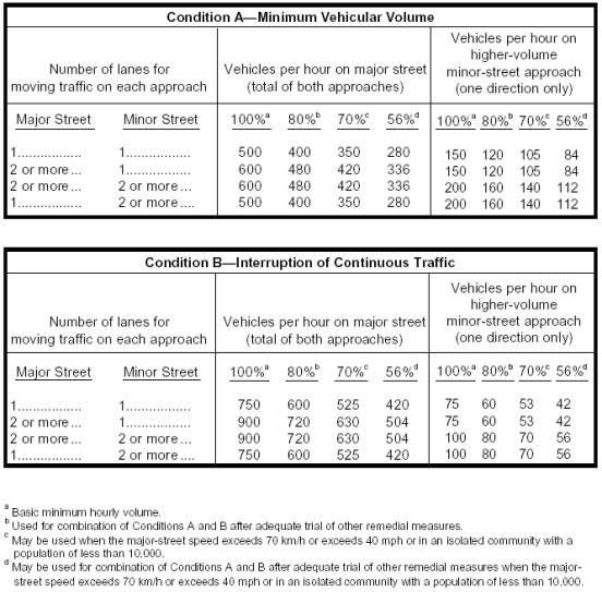
Key changes to Table 4C-1 include adding a column and footnote for 56% traffic volumes to correspond to the criteria for a combination of Conditions A and B as reflected in the text.
14. Page 4C-6, Section 4C.02, Warrant 1, Eight-Hour Vehicular Volume. Omit the Guidance at the top of the page, as it has been moved to page 4C-4; insert a new Option:
If the posted or statutory speed limit or the 85th-percentile speed on the major street exceeds 70 km/h or exceeds 40 mph, or if the intersection lies within the built-up area of an isolated community having a population of less than 10,000, the traffic volumes in the 56 percent columns in Table 4C-1 may be used in place of the 80 percent columns.
Insert a new Support:
It is intended that Warrant 1 be treated as a single warrant. If Condition A is satisfied, then the criteria for Warrant 1 is satisfied and Condition B and the combination of Conditions A and B are not applicable. Similarly, if Condition B is satisfied, then the criteria for Warrant 1 is satisfied and the combination of Conditions A and B is not applicable.
15. Page 4C-6, Section 4C.03, Warrant 2, Four-Hour Vehicular Volume. Under Option, change: “If the posted or statutory speed limit or the 85th percentile speed on the major street exceeds 70 km/h (40 mph),…” to: “If the posted or statutory speed limit or the 85th percentile speed on the major street exceeds 70 km/h or exceeds 40 mph,…”
16. Page 4C-6, Section 4C.04,Warrant 3, Peak Hour. Under Standard, change:
This signal warrant shall be applied only in unusual cases. Such cases include, but are not limited to, office complexes, manufacturing plants, industrial complexes, or high-occupancy vehicle facilities that attract or discharge large numbers of vehicles over a short time.
to:
This signal warrant shall be applied only in unusual cases, such as office complexes, manufacturing plants, industrial complexes, or high-occupancy vehicle facilities that attract or discharge large numbers of vehicles over a short time.
17.
Page 4C-7, Figure 4C-1. Warrant 2, Four-Hour Vehicular Volume. In the Y-axis caption at left, change: “HIGH VOLUME” to: “HIGHER-VOLUME”.
18. Page 4C-7, Figure 4C-2. Warrant 2, Four-Hour Vehicular Volume (70% Factor). In the Y-axis caption at left, change: “HIGH VOLUME” to: “HIGHER-VOLUME”; in the subtitle of the figure change: “(Community less than 10,000 population or above 70 km/h (40 mph) on major street)” to: “(Community less than 10,000 population or above 70 km/h or above 40 mph on major street)”.
19. Page 4C-8, Section 4C.04, Warrant 3, Peak Hour. Under Option, change: “If the posted or statutory speed limit or the 85th percentile speed on the major street exceeds 70 km/h (40 mph),…” to: “If the posted or statutory speed limit or the 85th percentile speed on the major street exceeds 70 km/h or exceeds 40 mph,…”
20. Page 4C-9, Figure 4C-3. Warrant 3, Peak Hour. In the Y-axis caption at left, change: “HIGH VOLUME” to: “HIGHER-VOLUME”.
21.
Page 4C-9, Figure 4C-4. Warrant 3, Peak Hour (70% Factor). In the Y-axis caption at left, change “HIGH VOLUME” to “HIGHER-VOLUME"; in
the subtitle of the figure change: “(Community less than 10,000 population or
above 70 km/h (40 mph) on major street)” to: “(Community less than 10,000
population or above 70 km/h or above 40 mph on major street)”.
22. Page 4C-10, Section 4C.05, Warrant 4, Pedestrian Volume. Under Standard, in the last paragraph change: “If a traffic control signal is justified by both this signal warrant and a traffic engineering study, the traffic control signal shall be equipped with pedestrian signal heads conforming to requirements set forth in Chapter 4E.” to: “If this warrant is met and a traffic control signal is justified by an engineering study, the traffic control signal shall be equipped with pedestrian signal heads conforming to requirements set forth in Chapter 4E.”; under Guidance, change:
If a traffic control signal is justified by both this signal warrant and a traffic engineering study:
A. If installed within a signal system, the traffic control signal should be coordinated.
B. At an intersection, the traffic control signal should be traffic-actuated and should include pedestrian detectors. As a minimum, it should have semiactuated operation, but full-actuated operation with detectors on all approaches might also be appropriate.
C. At nonintersection crossings, the traffic control signal should be pedestrian-actuated, parking and other sight obstructions should be prohibited for at least 30 m (100 ft) in advance of and at least 6.1 m (20 ft) beyond the crosswalk, and the installation should include suitable standard signs and pavement markings.
to:
If this warrant is met and a traffic control signal is justified by an engineering study, then:
A. If at an intersection, the traffic control signal should be traffic-actuated and should include pedestrian detectors. As a minimum, it should have semiactuated operation, but full-actuated operation with detectors on all approaches might also be appropriate.
B. If at a nonintersection crossing, the traffic control signal should be pedestrian-actuated, parking and other sight obstructions should be prohibited for at least 30 m (100 ft) in advance of and at least 6.1 m (20 ft) beyond the crosswalk, and the installation should include suitable standard signs and pavement markings.
C. Furthermore, if installed within a signal system, the traffic control signal should be coordinated.
23. Page 4C-11 and 4C-12, Section 4C.06, Warrant 5, School Crossing. Under Guidance, change:
If a traffic control signal is justified by both this signal warrant and an engineering study:
A. If installed within a signal system, the traffic control signal should be coordinated.
B. At an intersection, the traffic control signal should be traffic-actuated and should include pedestrian detectors. As a minimum, it should have semiactuated operation, but full-actuated operation with detectors on all approaches might also be appropriate.
C. At nonintersection crossings, the traffic control signal should be pedestrian-actuated, parking and other sight obstructions should be prohibited for at least 30 m (100 ft) in advance of and at least 6.1 m (20 ft) beyond the crosswalk, and the installation should include suitable standard signs and pavement markings.
to:
If this warrant is met and a traffic control signal is justified by an engineering study, then:
A. If at an intersection, the traffic control signal should be traffic-actuated and should include pedestrian detectors. As a minimum, it should have semiactuated operation, but full-actuated operation with detectors on all approaches might also be appropriate.
B. If at a nonintersection crossing, the traffic control signal should be pedestrian-actuated, parking and other sight obstructions should be prohibited for at least 30 m (100 ft) in advance of and at least 6.1 m (20 ft) beyond the crosswalk, and the installation should include suitable standard signs and pavement markings.
C. Furthermore, if installed within a signal system, the traffic control signal should be coordinated.
24. Page 4C-14, Section 4C.08, Warrant 7, Crash Experience. After the Standard, at the end of the Section, insert a new Option:
If the posted or statutory speed limit or the 85th percentile speed on the major street exceeds 70 km/h or exceeds 40 mph, or if the intersection lies within the built-up area of an isolated community having a population of less than 10,000, the traffic volumes in the 56 percent columns in Table 4C-1 may be used in place of the 80 percent columns.
25. Page 4D-1, Section 4D.01, General. Under the Standard, change:
A traffic control signal shall be operated in either a steady (stop-and-go) mode or a flashing mode at all times.
A traffic control signal shall control traffic only at the intersection or midblock location where the signal faces are placed.
STOP signs shall not be used in conjunction with any traffic control signal operation, except in either of the following cases:
B. If a minor street or driveway is located within or adjacent to the area controlled by the traffic control signal, but does not require separate traffic signal control because an extremely low potential for conflict exists.
When a traffic control signal is not in operation, such as before it is placed in service, during seasonal shutdowns, or when it is not desirable to operate the traffic control signal, the signal faces shall be covered, turned, or taken down to clearly indicate that the traffic control signal is not in operation.
to:
When a traffic control signal is not in operation, such as before it is placed in service, during seasonal shutdowns, or when it is not desirable to operate the traffic control signal, the signal faces shall be covered, turned, or taken down to clearly indicate that the traffic control signal is not in operation.
A traffic control signal shall control traffic only at the intersection or midblock location where the signal faces are placed.
STOP signs shall not be used in conjunction with any traffic control signal operation, except in either of the following cases:
B. If a minor street or driveway is located adjacent to the area controlled by the traffic control signal, but does not require separate traffic signal control because an extremely low potential for conflict exists.
26. Page 4D-1, Section 4D.01, General. Under Guidance, insert the following paragraph as the first paragraph: “Signalized midblock crosswalks should be located such that they are at least 30 m (100 ft) from side streets and driveways that are controlled by STOP signs or YIELD signs.”
27. Page 4D-3, Section 4D.03, Provisions for Pedestrians. Under Guidance, change: “Safety considerations should include the installation, where appropriate, of accessible pedestrian signals (see Sections 4E.06 and 4E.08)…” to: “Safety considerations should include the installation, where appropriate, of accessible pedestrian signals (see Sections 4E.06 and 4E.09)…”
28. Pages 4D-3 through 4D-5, Section 4D.04, Meaning of Vehicular Signal Indications. Under Standard, in the first paragraph change: “Unless otherwise determined by law, the following meanings shall be given…” to: “The following meanings shall be given…”; in Item A, subitem 1, in the first sentence change: “Traffic, except pedestrians, facing a CIRCULAR GREEN signal indication may proceed…” to: “Traffic, except pedestrians, facing a CIRCULAR GREEN signal indication is permitted to proceed…”; in Item A, subitem 2, in the first sentence change: “Traffic, except pedestrians, facing a GREEN ARROW signal indication, shown alone or in combination with another signal indication, may cautiously enter…” to: “Traffic, except pedestrians, facing a GREEN ARROW signal indication, shown alone or in combination with another signal indication, is permitted to cautiously enter…”; in Item A, subitem 3, change:
Unless otherwise directed by a pedestrian signal head, pedestrians facing any green signal indication, except when the signal indication is a turn arrow for a vehicular movement in conflict with the desired path of the pedestrian, may proceed across the roadway within any marked or unmarked crosswalk.
to:
Unless otherwise directed by a pedestrian signal head, pedestrians facing any green signal indication, except when the sole green signal indication is a turn arrow, are permitted to proceed across the roadway within any marked or unmarked crosswalk. The pedestrian shall yield the right-of-way to vehicles lawfully within the intersection at the time that the green signal indication is first shown.
In Item C, subitem 1, second paragraph, in the first sentence change: “Except when a sign is in place prohibiting a turn on red or a RED ARROW signal indication is displayed, vehicular traffic facing a CIRCULAR RED signal indication may enter the intersection…” to: “Except when a sign is in place prohibiting a turn on red or a RED ARROW signal indication is displayed, vehicular traffic facing a CIRCULAR RED signal indication is permitted to enter the intersection…”; in Item C, subitem 2, change: “Vehicular traffic facing a steady RED ARROW signal indication shall not enter the intersection to make the movement indicated by the arrow (except as described in the Option below) and, unless entering the intersection…” to: “Vehicular traffic facing a steady RED ARROW signal indication shall not enter the intersection to make the movement indicated by the arrow and, unless entering the intersection…” and add a second paragraph to Item C, subitem 2:
When an R10-15 sign (see Section 2B.40) is in place permitting a turn on a RED ARROW signal indication, vehicular traffic facing a RED ARROW signal indication is permitted to enter the intersection to turn right, or to turn left from a one-way street into a one-way street, after stopping. Such vehicular traffic shall yield the right-of-way to pedestrians lawfully within an adjacent crosswalk and to other traffic lawfully using the intersection.
In Item D, subitem 1, change: “Flashing yellow—When a yellow lens is illuminated with rapid intermittent flashes, vehicular traffic may proceed through the intersection or past such signal indication only with caution.” to: “Flashing yellow—When a yellow lens is illuminated with rapid intermittent flashes, vehicular traffic is permitted to proceed through the intersection or past such signal indication only with caution.”
29. Page 4D-6, Section 4D.04, Meaning of Vehicular Signal Indications. Remove the Option in its entirety.
30. Page 4D-6, Section 4D.05, Application of Steady Signal Indications. Under the Standard, in Item A, subitem 2, on the last line, change: “…turn signal faces.” to: “…turn signal faces, or in protected/permissive mode left-turn operation with separate left-turn signal faces (see Section 4D.06)”; in Item B, add a fourth subitem:
4. Shall not be displayed to an approach from which drivers are turning left permissively unless one of the following conditions exists:
(a) A steady CIRCULAR YELLOW signal indication is also being shown simultaneously to the opposing approach;
(b) A separate left-turn signal face is provided and operated as described in Section 4D.06;
(c) Drivers are advised of the operation if it occurs regularly by the installation near the left-most signal head of a W25-1 sign (see Section 2C.54) with the legend CAUTION ONCOMING GREEN EXTENDED; or
(d) Drivers are advised of the operation if it occurs only occasionally, such as during a preemption sequence or because of the skipping of actuated phases, by the installation near the left-most signal head of a W25-2 sign (see Section 2C.54) with the legend CAUTION ONCOMING GREEN MAY BE EXTENDED.
31. Page 4D-7, Section 4D.05, Application of Steady Signal Indications. In Item D, in the second sentence change: “Turning on a steady RED ARROW signal indication shall not be permitted.” to: “Except as described in Item C.2 of Section 4D.04, turning on a steady RED ARROW signal indication shall not be permitted.”
32. Page 4D-8, Section 4D.05, Application of Steady Signal Indications. In Item F, subitem 2, add a second sentence:
If U-turns are permitted from the approach and if drivers making a right turn from the conflicting approach to the left are simultaneously being shown a right-turn GREEN ARROW signal indication, drivers making a U-turn shall be advised of the operation by the installation near the left-turn signal face of a U-TURN YIELD TO RIGHT TURN (R10-16) sign (see Section 2B.40).
33. Pages 4D-9 through 4D-11, Section 4D.06, Application of Steady Signal Indications for Left Turns. Under Standard, in Item A, change:
Permissive Only Mode—The signal indication for permissive only mode left turns shall be the same color as the signal indication for through traffic. A separate signal indication or signal face for left turns shall not be required.
to:
Permissive Only Mode—The signal indications for permissive only mode left turns shall be provided in either a shared signal face or a separate signal face. Any permissive only left-turn signal face that always simultaneously displays the same color of circular indication that the adjacent through signal face or faces display shall be considered to be a shared signal face, regardless of where the left-turn signal face is positioned and regardless of how many adjacent through signal faces are provided. Any permissive only left-turn signal face that sometimes displays a different color of circular signal indication than the adjacent through signal faces display shall be considered a separate signal face. The requirements for each type of signal face are as follows:
1. If a shared signal face is provided, it shall be considered an approach signal face and the signal indications for permissive only mode left turns shall be the same color as the signal indications for through traffic.
2. If a separate left-turn signal face is provided for permissive only left turns, it shall meet the following requirements:
(a) During the permissive left turn movement, the left-turn signal face shall display a CIRCULAR GREEN signal indication.
(b) If the CIRCULAR GREEN and CIRCULAR YELLOW signal indications in the left-turn signal face are visibility-limited from the adjacent through movement, the left-turn signal face shall not be required to simultaneously display the same color of circular signal indication as the signal faces for the adjacent through movement.
(c) If the CIRCULAR GREEN and CIRCULAR YELLOW signal indications in the left-turn signal face are visibility-limited from the adjacent through movement, the display of a CIRCULAR GREEN signal indication for a permissive left turn movement while the signal faces for the adjacent through movement display CIRCULAR RED signal indications and the opposing left-turn signal faces display left-turn GREEN ARROW signal indications for a protected left-turn movement shall be permitted.
(d) If the left-turn signal face does not simultaneously display the
same color of circular signal indication as the signal faces for the adjacent
through movement, a LEFT TURN YIELD ON GREEN (symbolic green ball) (R10-12)
sign or a LEFT TURN SIGNAL -- YIELD ON GREEN (symbolic green ball) (R10-21)
sign (see Figure 2B-18) shall be used.
In Item B, subitem 2, in the third sentence change: “Unless the CIRCULAR RED signal indication is shielded, hooded, louvered, positioned, or designed such that it cannot be seen by drivers in the through lane(s), either a LEFT TURN SIGNAL sign (R10-10) or a visibility-limited CIRCULAR RED signal indication shall be used.” to: “Unless the CIRCULAR RED signal indication is shielded, hooded, louvered, positioned, or designed such that it is not readily visible to drivers in the through lane(s), a LEFT TURN SIGNAL sign (R10-10) shall be used.”;
Also, in Item C change:
C. Protected/Permissive Mode—The signal indications for protected/permissive mode left turns shall be provided either in a shared signal face (to be shared by left-turning and through traffic) or in a separate signal face intended to be exclusively used by left-turning traffic.
If a shared signal face is provided, it shall be considered an approach signal face, and shall meet the following requirements:
1. During the protected left-turn movement, the signal face shall simultaneously display:
(a) A left-turn GREEN ARROW signal indication, and
(b) A circular signal indication that is the same color as the signal indication for the adjacent through lane on the same approach as the protected left turn.
During the protected left-turn movement, the signal faces for through traffic on the opposing approach shall simultaneously display CIRCULAR RED signal indications.
2. During the permissive left-turn movement, all signal faces on the approach shall display CIRCULAR GREEN signal indications.
3. All signal faces on the approach shall simultaneously display the same color of circular signal indications to both through and left-turn road users.
4. A supplementary sign shall not be required. If used, it shall be a LEFT TURN YIELD ON GREEN (symbolic green ball) sign (R10-12).
If a separate signal face is provided, it shall be considered a left-turn signal face, and shall meet the following requirements:
1. During the protected left-turn movement, the left-turn signal face shall simultaneously display:
(a) A left-turn GREEN ARROW signal indication, and
(b) A CIRCULAR RED signal indication.
During the protected left-turn movement, the signal faces for through traffic on the opposing approach shall simultaneously display CIRCULAR RED signal indications.
2. During the permissive left-turn movement, the left-turn signal face shall display a CIRCULAR GREEN signal indication.
3. If the CIRCULAR GREEN and CIRCULAR YELLOW signal indications in the left-turn signal face are visibility-limited from the adjacent through movement, the left-turn signal face shall not be required to simultaneously display the same color of circular signal indication as the signal faces for the adjacent through movement.
4. If the CIRCULAR GREEN and CIRCULAR YELLOW signal indications in the left-turn signal face are visibility-limited from the adjacent through movement, the display of a CIRCULAR GREEN signal indication for a permissive left-turn movement while the signal faces for the adjacent through movement display CIRCULAR RED signal indications and the opposing left-turn signal face displays a left-turn GREEN ARROW for a protected left-turn movement shall be permitted.
5. If the left-turn signal face does not simultaneously display the same color of circular signal indication as the signal faces for the adjacent through movement, a combination of a LEFT TURN SIGNAL sign (R10-11) and a LEFT TURN YIELD ON GREEN (symbolic green ball) sign (R10-12) sign shall be used.
to:
C. Protected/Permissive Mode—The signal indications for protected/permissive mode left turns shall be provided in either a shared signal face or a separate signal face. Any protected/permissive left-turn signal face that always simultaneously displays the same color of circular signal indication that the adjacent through signal faces display shall be considered to be a shared signal face, regardless of where the left-turn signal face is positioned and regardless of how many adjacent through signal faces are provided. Any protected/permissive left-turn signal face that sometimes displays a different color of circular signal indication than the adjacent through signal faces display shall be considered to be a separate signal face. The requirements for each type of signal face are as follows:
1. If a shared signal face is provided, it shall be considered an approach signal face, and shall meet the following requirements:
(a) During the protected left-turn movement, the signal face shall simultaneously display a left-turn GREEN ARROW signal indication and a circular signal indication that is the same color as the signal indication for the adjacent through lane on the same approach as the protected left turn. During the protected left-turn movement, the signal faces for through traffic on the opposing approach shall simultaneously display CIRCULAR RED signal indications.
(b) During the permissive left-turn movement, all signal faces on the approach shall display CIRCULAR GREEN signal indications.
(c) All signal faces on the approach shall simultaneously display the same color of circular signal indications to both through and left-turn road users.
(d) A supplementary sign shall not be required. If used, it shall be a LEFT TURN YIELD ON GREEN (symbolic green ball) (R10-12) sign (see Figure 2B-18).
If a separate signal face is provided, it shall be considered a left-turn signal face, and shall meet the following requirements:
(a) During the protected left-turn movement, the left-turn signal face shall display a left-turn GREEN ARROW signal indication. During the protected left-turn movement, the signal faces for through traffic on the opposing approach shall simultaneously display CIRCULAR RED signal indications.
(b) During the permissive left-turn movement, the left-turn signal face shall display a CIRCULAR GREEN signal indication.
(c) If the CIRCULAR GREEN and CIRCULAR YELLOW signal indications in the left-turn signal face are visibility-limited from the adjacent through movement, the left-turn signal face shall not be required to simultaneously display the same color of circular signal indication as the signal faces for the adjacent through movement.
(d) If the CIRCULAR GREEN and CIRCULAR YELLOW signal indications in the left-turn signal face are visibility-limited from the adjacent through movement, the display of a CIRCULAR GREEN signal indication for a permissive left-turn movement while the signal faces for the adjacent through movement display CIRCULAR RED signal indications and the opposing left-turn signal face displays a left-turn GREEN ARROW for a protected left-turn movement shall be permitted.
(e) If the left-turn signal face does not simultaneously display the same color of circular signal indication as the signal faces for the adjacent through movement, a LEFT TURN SIGNAL-- YIELD ON GREEN (symbolic green ball) sign (R10-21) sign (see Figure 2B-18) shall be used.
34. Page 4D-12, Section 4D.07, Application of Steady Signal Indications for Right Turns. Under Standard, item B, subitem 2, in the third sentence change:
Unless the CIRCULAR RED signal indication is shielded, hooded, louvered, positioned, or designed such that it cannot be seen by drivers in the through lane(s), either a RIGHT TURN SIGNAL sign (R10-10) or a visibility-limited CIRCULAR RED signal indication shall be used.
to:
Unless the CIRCULAR RED signal indication is shielded, hooded, louvered, positioned, or designed such that it is not readily visible to drivers in the through lane(s), a RIGHT TURN SIGNAL sign (R10-10R) shall be used.
35. Page 4D-14, Section 4D.09, Unexpected Conflicts During Green or Yellow Intervals. Under Standard, in item A, change: “Other vehicles moving on a green or yellow signal indication.” to: “Other vehicles moving on a green or yellow signal indication, except for the situation regarding U-Turns described in Item F.2 of Section 4D.05.”
36. Page 4D-15, Section 4D.10, Yellow Change and Red Clearance Intervals. Under Option, change: “The yellow change interval may be followed by a red clearance interval to provide additional time before conflicting traffic movements are released.” to: “The yellow change interval may be followed by a red clearance interval to provide additional time before conflicting traffic movements, including pedestrians, are released.”
37. Page 4D-18, Section 4D.12, Flashing Operation of Traffic Control Signals. Under Guidance, change: “Any steady red clearance interval provided during the change from red-red flashing mode to steady (stop-and-go) mode should have a maximum duration of 6 seconds.” to: “The steady red clearance interval provided during the change from red-red flashing mode to steady (stop-and-go) mode should have a duration of 6 seconds.”; under Support, change: “Section 4E.08 contains information…” to: “Section 4E.09 contains information…”
38. Page 4D-19, Section 4D.13, Preemption and Priority Control of Traffic Control Signals. Change the first Support to an Option; after the new Option, begin a new Support at paragraph 2; change: “Preemption control (see definition in Section 4A.02) is typically given to emergency vehicles and to vehicles such as boats and trains.” to: “Preemption control (see definition in Section 4A.02) is typically given to trains, boats, emergency vehicles, and light rail transit.”; change: “Typically, the order of priority is: boat, train, heavy vehicle (fire vehicle, emergency medical service), light vehicle (police), light rail, rubber-tired transit.” to:“Typically, the order of priority is: train, boat, heavy vehicle (fire vehicle, emergency medical service), light vehicle (police), light rail transit, rubber-tired transit.”
39. Pages 4D-23 and 4D-24, Section 4D.15, Size, Number, and Location of Signal Faces by Approach. Under Standard, change item D from:
D. Except where the width of an intersecting roadway or other conditions make it physically impractical:
1. A signal face installed to satisfy the distance requirements as described in Paragraphs B and C in the first Standard of this Section, and at least one and preferably both of the signal faces required by Paragraph A in this Standard shall be located:
(a) Not less than 12 m (40 ft) beyond the stop line.
(b) Not more than 45 m (150 ft) beyond the stop line unless a supplemental near side signal face is provided.
(c) As near as practical to the line of the driver's normal view, if mounted over the roadway.
2. A signal face installed to satisfy the distance requirements as described in Paragraphs B and C in the first Standard of this Section and at least one and preferably both of the signal faces required by Paragraph A in this Standard shall be located no higher than at a maximum height to the top of the signal housing mounted over a roadway of 7.8 m (25.6 ft) above the pavement (see Section 4D.17). For viewing distances between 12 m (40 ft) and 16 m (53 ft) from the stop line, the maximum mounting height to the top of the signal housing shall be as shown on Figure 4D-1. (See Section 4D.17 for additional information regarding mounting heights.)
3. At least one and preferably both of the signal faces required by Paragraph A above shall be located between two lines intersecting with the center of the approach at a point 3 m (10 ft) behind the stop line, one making an angle of approximately 20 degrees to the right of the center of the approach extended, and the other making an angle of approximately 20 degrees to the left of the center of the approach extended (see Figure 4D-2).
4. If both of the signal faces required by Paragraph A above are post-mounted, they shall both be on the far side of the intersection, one on the right and one on the left of the approach lane(s).
to:
D. Except where the width of an intersecting roadway or other conditions make it physically impractical:
1. A signal face installed to satisfy the requirements of Items B and C in this Standard, and at least one and preferably both of the signal faces required by Item A in this Standard shall be located:
(a) Not less than 12 m (40 ft) beyond the stop line.
(b) Not more than 55 m (180 ft) beyond the stop line unless a supplemental near side signal face is provided.
(c) As near as practical to the line of the driver's normal view, if mounted over the roadway.
2. Where the nearest signal face is located between 45 and 55 m (150 and 180 ft) beyond the stop line, engineering judgment of the conditions, including the worst-case visibility conditions, shall be used to determine if the provision of a supplemental near side signal face would be beneficial.
3. A signal face installed to satisfy the requirements of Items B and C in this Standard, and at least one and preferably both of the signal faces required by Item A in this Standard shall be located no higher than at a maximum height to the top of the signal housing mounted over a roadway of 7.8 m (25.6 ft) above the pavement (see Section 4D.17). For viewing distances between 12 m (40 ft) and 16 m (53 ft) from the stop line, the maximum mounting height to the top of the signal housing shall be as shown on Figure 4D-1. (See Section 4D.17 for additional information regarding mounting heights.)
4. At least one and preferably both of the signal faces required by Item A in this Standard shall be located between two lines intersecting with the center of the approach at a point 3 m (10 ft) behind the stop line, one making an angle of approximately 20 degrees to the right of the center of the approach extended, and the other making an angle of approximately 20 degrees to the left of the center of the approach extended (see Figure 4D-2).
5. If both of the signal
faces required by Item A in this Standard are post-mounted, they shall both be
on the far side of the intersection, one on the right and one on the left of
the approach lane(s).
40. Page 4D-26, Figure 4D-2, Horizontal Location of Signal Faces. Change the triangular area from having two shaded areas (with lines slanting downward to the right and with lines slanting upward to the right) to having three shaded areas (with lines slanting downward to the right, lines slanting both downward to the right and upward to the right, and with lines slanting upward to the right); change the dimensions shown vertically on the figure to the horizontal lines through the triangular area from “12 m* (40 ft), 35 m** (120 ft), and 45 m*** (150 ft)” to “12 m* (40 ft), 35 m** (120 ft), 45 m*** (150 ft), and 55 m**** (180 ft)”; in the legend area at the top right of the figure entitled “Location of signal heads within these areas:” change the shading in the second box from lines slanting downward to the right to lines slanting both upward to the right and downward to the right, and add a new box with shading by lines slanting downward to the right and a caption of “300 mm (12 in) signal lenses”; and change the last footnote at the bottom right of the figure from “*** Maximum distance from stop line for 200 mm (8 inch) signal faces when near side supplemental signal face is used and maximum distance from stop line for 300 mm (12 inch) signal faces, unless a near-side supplemental signal face is used.” To “*** Maximum distance from stop line for 200 mm (8 inch) signal faces when near side supplemental signal face is used. **** Maximum distance from stop line for 300 mm (12 inch) signal faces, unless a near-side supplemental signal face is used.”
41. Page 4D-27, Section 4D.15, Size, Number, and Location of Signal Faces by Approach. Under Guidance, change: “If a signal face controls a specific lane or lanes of approach…’’ to: “If a signal face controls a specific lane or lanes of an approach…’
42. Page 4D-27 and 4D-28, Section 4D.15, Size, Number, and Location of Signal Faces by Approach. Under Option, in the second paragraph, change: “…upon arrival at the signalized intersection.” to: “…upon arrival at the signalized location.”
43. Pages 4D-28 and 4D-29, Section 4D.16, Number and Arrangement of Signal Sections in Vehicular Traffic Control Signal Faces. In the seventh paragraph of the Standard, change: “In vertically arranged signal faces, each YELLOW ARROW signal lens shall be located immediately above the GREEN ARROW signal lens to which it applies. If a variable indication signal section…” to: “In vertically arranged signal faces, each YELLOW ARROW signal lens shall be located immediately above the GREEN ARROW signal lens to which it applies. If a dual-arrow signal section…”; in the eighth paragraph of the Standard, change:
In horizontally arranged signal faces, the YELLOW ARROW signal lens shall be located immediately to the left of the GREEN ARROW signal lens. If a variable indication signal section…is used, the variable left-turn arrow signal lens shall be located immediately to the right of the CIRCULAR YELLOW…, and the variable right-turn arrow signal lens shall be located to the right of all other signal lenses.
to:
In horizontally arranged signal faces, the YELLOW ARROW signal lens shall be located immediately to the left of the GREEN ARROW signal lens. If a dual-arrow signal section…is used, the dual left-turn arrow signal lens shall be located immediately to the right of the CIRCULAR YELLOW…and the dual right-turn arrow signal lens shall be located to the right of all other signal lenses.
At the end of the Standard, change: “C. If adjacent signal indications in a signal face are not identical, their arrangement shall follow Paragraph A or B above, as applicable.” to: “C. If adjacent signal indications in a signal face are not identical, their arrangement shall follow Items A or B above, as applicable.”
44.
Page 4D-30, Section 4D.16, Number and
Arrangement of Signal Sections in Vehicular Traffic Control Signal Faces. Under Option, in the second paragraph
change: “lateral clearance…” to: “lateral separation spacing…”
45.
Page 4D-32, Section 4D.17, Visibility, Shielding, and
Positioning of Signal Faces. Under
Guidance, in the final paragraph change: “A signal backplate for target value
enhancement should be used on signal faces viewed against a bright sky or
bright or confusing backgrounds.” to: “The use of a signal backplate for target
value enhancement should be considered on signal faces viewed against a bright
sky or bright or confusing backgrounds.”
46. Page 4D-33, Section 4D.18, Design, Illumination, and Color of Signal Sections. Under Standard, in the fifth paragraph, change: “Each arrow signal indication shall emit a single color: red, yellow, or green except that the alternate display (variable indication signal section)…” to “Each arrow signal indication shall emit a single color: red, yellow, or green except that the alternate display (dual-arrow signal section)…”
47. Page 4D-34, Section 4D.18, Design, Illumination, and Color of Signal Sections. Remove the last Guidance in its entirety.
48. Pages 4D-34 and 4D-35, Section 4D.19, Lateral Placement of Signal Supports and Cabinets. Under Guidance, in Item D change: “Controller cabinets should be located as far as is practical from the edge of the roadway.” to: “Controller cabinets should be located as far as practical from the edge of the roadway.”
49. Page 4D-36, Section 4D.20, Temporary Traffic Control Signals Under Guidance, change: “For use of temporary traffic control signals in temporary traffic control zones, reference should be made to Section 6F.74.” to: “For use of temporary traffic control signals in temporary traffic control zones, reference should be made to Section 6F.76.”
50. Page 4D-36, Section 4D.21, Traffic Signal Signs, Auxiliary. Under Standard, change: “The minimum clearance of the total assembly…” to: “The minimum vertical and horizontal clearance of the total assembly”; under Guidance, change: “When a traffic signal sign at a highway traffic signal is applicable to a particular movement, the sign should be located adjacent to the signal face for that movement.” to: “Traffic signal signs should be located adjacent to the signal face to which they apply.”
51. Page 4E-1, Section 4E.02, Meaning of Pedestrian Signal Indications. Change the Section title to: “Section 4E.02 Meaning of Pedestrian Signal Head Indications”; under Standard, change: “The pedestrian signal indications shall have the following meanings:” to: “Pedestrian signal head indications shall have the following meanings:”; in item A change:
A steady WALKING PERSON (symbolizing WALK) signal indication means that a pedestrian facing the signal indication may start to cross the roadway in the direction of the signal indication, possibly in conflict with turning vehicles.
to:
A
steady WALKING PERSON (symbolizing WALK) signal indication means that a
pedestrian facing the signal indication is permitted to start to cross the
roadway in the direction of the signal indication, possibly in conflict with
turning vehicles. The pedestrian shall
yield the right-of-way to vehicles lawfully within the intersection at the time
that the WALKING PERSON (symbolizing WALK) signal indication is first shown.
52. Page 4E-2, Section 4E.03, Application of Pedestrian Signal Heads. Under Standard, item A, change: “If a traffic control signal is justified by a traffic engineering study…” to: “If a traffic control signal is justified by an engineering study”; at the end of item B add “or”; at the end of item C remove “and/or”; remove item D entirely.
53. Page 4E-2, Section 4E.04, Size, Design, and Illumination of Pedestrian Signal Indications. Change the Section title to: “Section 4E.04 Size, Design, and Illumination of Pedestrian Signal Head Indications”.
54. Pages 4E-2 and 4E-3, Section 4E.04, Size, Design , and Illumination of Pedestrian Signal Indications. Under Standard, in the first paragraph, after the second sentence, insert a new sentence: “The symbol designs shall be solid; outline style symbols shall not be used”; in the fifth paragraph, change: “…symbols shall not be readily visible to pedestrians at the far end of the crosswalk that the pedestrian signal indications control.” to: “…symbols shall not be readily visible to pedestrians at the far end of the crosswalk that the pedestrian signal head indications control.”; in the last paragraph, change: “For pedestrian signal indications, the symbols shall be at least 150 mm (6 in) high.” to: “For pedestrian signal head indications, the symbols shall be at least 150 mm (6 in) high.”; after the existing final paragraph of the Standard, insert a new, final paragraph:
The light source of a flashing UPRAISED HAND (symbolizing DONT WALK) signal indication shall be flashed continuously at a rate of not less than 50 nor more than 60 times per minute. The illuminated period of each flash shall be not less than half and not more than two-thirds of the total flash cycle.
55. Page 4E-3, Section 4E.04, Size, Design, and Illumination of Pedestrian Signal Head Indications. Under Guidance, change: “Pedestrian signal indications should be conspicuous and recognizable to pedestrians…” to: “Pedestrian signal head indications should be conspicuous and recognizable to pedestrians…”; change: “For crosswalks where the pedestrian enters the crosswalk more than 30 m (100 ft) from the pedestrian signal indications,” to: “For crosswalks where the pedestrian enters the crosswalk more than 30 m (100 ft) from the pedestrian signal head indications,”; following the Guidance, at the end of the Section insert a new Option: “An animated eyes symbol may be added to a pedestrian signal head in order to prompt pedestrians to look for vehicles in the intersection during the time that the WALK signal indication is displayed.”; following the new Option, insert a new second Standard:
If used, the animated eyes symbol shall consist of an outline of a pair of white steadily-illuminated eyes with white eyeballs that scan from side to side at a rate of approximately once per second. The animated eyes symbol shall be at least 300 mm (12 in) wide with each eye having a width of at least 125 mm (5 in) and a height of at least 62 mm (2.5 in). The animated eyes symbol shall be illuminated at the start of the walk interval and shall terminate at the end of the walk interval.
56. Page 4E-4, Figure 4E-1, Typical Pedestrian Signal Indications. Remove the illustration of the one-section outlined symbol type of pedestrian signal indications and the caption “One Section (Outlined Symbol)”; and change the existing second caption from: “One Section (Solid Symbol)” to: “One Section”.
57. Page 4E-5, Section 4E.06, Accessible Pedestrian Signals. Under first Support, change:
The primary technique that pedestrians who have visual disabilities use to cross streets at signalized intersections is to initiate their crossing when they hear the traffic in front of them stop and the traffic alongside them begin to move, corresponding to the onset of the green interval. This technique is effective at the many signalized intersections. The existing environment is often sufficient to provide the information that pedestrians who have visual disabilities need to operate safely at a signalized intersection. Therefore, many signalized intersections will not require any accessible pedestrian signals.
to:
The primary technique that pedestrians who have visual disabilities use to cross streets at signalized locations is to initiate their crossing when they hear the traffic in front of them stop and the traffic alongside them begin to move, corresponding to the onset of the green interval. This technique is effective at many signalized locations. The existing environment is often sufficient to provide the information that pedestrians who have visual disabilities need to operate safely at a signalized location. Therefore, many signalized locations will not require any accessible pedestrian signals.
Under the Guidance, change: “If a particular signalized intersection presents difficulties for pedestrians…” to: “If a particular signalized location presents difficulties for pedestrians...”; and under the second Support, change: “The factors that might make crossing at an intersection difficult for pedestrians….” to: “The factors that might make crossing at a signalized location difficult for pedestrians…”
58. Page 4E-6, Section 4E.06, Accessible Pedestrian Signals. Under Guidance, change: “The installation of accessible pedestrian signals at signalized intersections should be based on an engineering study,…” to: “The installation of accessible pedestrian signals at signalized locations should be based on an engineering study,…”
59. Pages 4E-7, Section 4E.06, Accessible Pedestrian Signals. Under Guidance, in the second paragraph, change:
Automatic volume adjustment in response to ambient traffic sound level should be provided up to a maximum volume of 89 dB. Where automatic volume adjustment is used, tones should be no more than 5 dB louder than ambient sound.
to:
Automatic volume adjustment in response to ambient traffic sound level should be provided up to a maximum volume of 89 dBA. Where automatic volume adjustment is used, tones should be no more than 5 dBA louder than ambient sound. The A-weighted sound pressure level should be measured according to “ISO 1996-1:1982” and “ISO 1996-2:1987” at a distance of 1 m (3.3 ft) from the transmitter (see Page i for the address for the International Organization for Standards).
60. Page 4E-8. Following existing Sections 4E.06, insert new Section numbered and titled: “Section 4E.07 Countdown Pedestrian Signals” and renumber subsequent sections accordingly. The new section reads as follows:
Option:
A pedestrian interval countdown display may be added to a pedestrian signal head in order to inform pedestrians of the number of seconds remaining to cross the street.
Standard:
If used, countdown pedestrian signals shall consist of Portland orange numbers that are at least 150 mm (6 in) in height on a black opaque background. The countdown pedestrian signal shall be located immediately adjacent to the associated UPRAISED HAND (symbolizing DONT WALK) pedestrian signal head indication.
If used, the display of the number of remaining seconds shall begin only at the beginning of the pedestrian change interval. After the countdown has terminated, the display shall remain dark until the beginning of the next countdown.
If used, the countdown pedestrian signal shall display the number of seconds remaining until the termination of the pedestrian change interval or until the termination of the concurrent vehicular phase’s green interval, whichever occurs first. Countdown displays during the walk interval shall not be used.
Guidance:
If used with a pedestrian signal head that does not have a concurrent vehicular phase, the countdown pedestrian signal should display the number of seconds minus four remaining in the pedestrian change interval such that the countdown’s zero point is reached approximately 4 seconds prior to the termination of the pedestrian change interval.
For
crosswalks where the pedestrian enters the crosswalk more than 30 m (100 ft)
from the countdown pedestrian signal display, the numbers should be at least
225 mm (9 in) in height.”
61. Page 4E-8, Section 4E.07, Pedestrian Detectors. Change Section number to: “Section 4E.08”; under Guidance, change: “When pedestrian actuation is used, pedestrian pushbutton detectors should be easy to use and conveniently located near each end of the crosswalks.” to: “When pedestrian actuation is used, pedestrian pushbutton detectors should be capable of easy activation and conveniently located near each end of the crosswalks.”
62. Page 4E-9, Section 4E.07, Pedestrian Detectors. Under the second Guidance, change: “If used, special purpose pushbuttons (to be operated only by authorized persons) should include a housing capable of being locked to prevent access by the general public.” to: “If used, special purpose pushbuttons (to be operated only by authorized persons) should include a housing capable of being locked to prevent access by the general public and do not need an instructional sign.”
63. Page 4E-9, Section 4E.07, Pedestrian Detectors. Under the second Standard, remove the first paragraph; after the second Standard, insert a new second Option: “At signalized locations with demonstrated need and subject to equipment capabilities, a detector with instructional signing may be installed to provide additional crossing time for pedestrians with special needs.”
64. Page 4E-10, Section 4E.08, Accessible Pedestrian Signal Detectors. Change the Section number to: “Section 4E.09”; change the first Support to become the first Standard; change: “An accessible pedestrian signal detector is a device designated to assist the pedestrian who has visual or physical disabilities in activating the pedestrian phase.” to: “An accessible pedestrian signal detector shall be defined as a device designated to assist the pedestrian who has visual or physical disabilities in activating the pedestrian phase.”; delete heading “Standard:” which follows the first Option; move the subsequent paragraph, “At accessible pedestrian signal locations with pedestrian actuation, each pushbutton shall activate both the walk interval and the accessible pedestrian signals.” to follow immediately after the text in the new first Standard. Under Guidance, in the second paragraph change: “Pushbuttons for accessible pedestrian signals should be located as follows:” to: “Pushbuttons for accessible pedestrian signals should be located (See Figure 4E-2) as follows:”; and in item D change: “Parallel to the crosswalk to be used (See Figure 4E-2).” to: “Parallel to the crosswalk to be used.”
65. Page 4E-11, Figure 4E-2. Change the title of the figure to: “Figure 4E-2. Typical Pushbutton Locations for Accessible Pedestrian Signals”; change the arrow symbols denoting the pushbuttons so that the arrows point toward and the arrow shafts are parallel to the nearest crosswalk; and extend the dimension lines to extend to the applicable poles.
66. Page 4E-12, Section 4E.08, Accessible Pedestrian Signal Detectors. Under Guidance, in the last sentence of the first paragraph, change: “Pushbutton locator tones should be no more than 5 dB louder than ambient sound.” to: “Pushbutton locator tones should be no more than 5 dBA louder than ambient sound.”; and under Option, in the first sentence of the second paragraph, change: “The audible tone(s) may be made louder (up to a maximum of 89 dB)…” to: “The audible tone(s) may be made louder (up to a maximum of 89 dbA)…”
67. Page 4E-12, Section 4E.09, Pedestrian Intervals and Signal Phases. Change the Section number to: “Section 4E.10”.
68. Pages 4E-13, Section 4E.09, Pedestrian Intervals and Signal Phases. Under the first Option, change: “If it is desired to favor the length of an opposing signal phase and if pedestrian volumes and characteristics do not require a 7-second walk interval, walk intervals as short as 4 seconds may be used.” to: “If pedestrian volumes and characteristics do not require a 7-second walk interval, walk intervals as short as 4 seconds may be used.”; under the second Guidance, change:
The pedestrian clearance time should be sufficient to allow a pedestrian crossing in the crosswalk who left the curb or shoulder during the WALKING PERSON (symbolizing WALK) signal indication to travel at a normal walking speed of 1.2 m (4 ft) per second, to at least the center of the farthest traveled lane or to a median of sufficient width for pedestrians to wait.
to:
The pedestrian clearance time should be sufficient to allow a pedestrian crossing in the crosswalk who left the curb or shoulder during the WALKING PERSON (symbolizing WALK) signal indication to travel at a normal walking speed of 1.2 m (4 ft) per second, to at least the far side of the traveled way or to a median of sufficient width for pedestrians to wait.
69. Page 4E-14, Section 4E.09, Pedestrian Intervals and Signal Phases. Under Option, in the first paragraph, change: “The pedestrian clearance time may be entirely contained within the vehicular green interval.” to: “The pedestrian clearance time may be entirely contained within the vehicular green interval, or may be entirely contained within the vehicular green and yellow change intervals.”
70. Page 4F-1, Section 4F.01, Application of Emergency-Vehicle Traffic Control Signals. Under Option, insert a new paragraph following the first paragraph: “An emergency Beacon may be installed instead of an emergency-vehicle traffic control signal under conditions described in Section 4F.04.”; and under Guidance, in the first paragraph, in the second sentence, change: “If a traffic control signal is justified under the signal warrants of Chapter 4C, and a decision is made to install a traffic control signal, it should be installed to the Standards required for that type of signal (see Chapter 4D).” to: “If one of the signal warrants of Chapter 4C is met and a traffic control signal is justified by an engineering study, and if a decision is made to install a traffic control signal, it should be installed based on the provisions of Chapter 4D.”
71. Page 4F-1, Section 4F.02, Design of Emergency-Vehicle Traffic Control Signals. Under Standard, change: “An Emergency Vehicle (W11-8) sign with an EMERGENCY SIGNAL AHEAD (W11-12P) supplemental plaque…” to: “An Emergency Vehicle (W11-8) sign (see Section 2C.36) with an EMERGENCY SIGNAL AHEAD (W11-12P) supplemental plaque…”
72. Page 4F-2, Section 4F.02, Design of Emergency-Vehicle Traffic Control Signals. Under Guidance, change: “At least one signal face for each approach on the major street should be located over the roadway.” to: “At least one of the two required signal faces for each approach on the major street should be located over the roadway.”; and under Option, change: “An approach that only serves emergency vehicles may be provided with only one signal face.” to: “An approach that only serves emergency vehicles may be provided with only one signal face consisting of one or more signal sections.”
73.
Page 4F-3, Section 4F.03, Operation
of Emergency-Vehicle Traffic Control Signals. Under Standard, in the first full paragraph, change: “semi- or fully traffic-actuated,” to: “fully or semi-traffic-actuated.”
74. Pages 4F-3. After Section 4F.03, insert a new Section numbered and titled: “Section 4F.04 Emergency Beacon”, The new Section reads:
Standard:
An Emergency Beacon shall be used only in conjunction with signs to warn
and control traffic at an unsignalized location where emergency vehicles enter
or cross a street or highway. An
Emergency Beacon shall be actuated only by authorized emergency or maintenance
personnel.
Support:
Ordinarily the Emergency Beacon is immediately adjacent to a fire station or rescue service facility, but in some cases the emergency services facility is on a side road, away from the point where emergency vehicles enter or cross the approaches equipped with Emergency Beacons.
Guidance:
An Emergency Beacon should only be used when both of the following criteria are satisfied:
A. The conditions justifying an emergency-vehicle traffic control signal (see Section 4F.01) are met.
B. An engineering study, considering the road width, approach speeds, and other pertinent factors, determines that an Emergency Beacon can be designed and located in compliance with the requirements contained in Chapter 4K, such that it effectively warns and controls traffic at the location.
Standard:
An Emergency Beacon shall consist of three signal sections, with a CIRCULAR YELLOW signal lens between two CIRCULAR RED signal lenses, aligned horizontally or vertically, in each signal face. Stop lines and EMERGENCY SIGNAL—STOP WHEN FLASHING RED (R10-14) signs (see Section 2B.40) shall be used with Emergency Beacons.
Emergency Beacons shall be dark (not illuminated) during periods between actuations.
Upon actuation by authorized emergency personnel, the Emergency Beacon shall display a flashing yellow signal indication, followed by a steady yellow change interval, prior to displaying two CIRCULAR RED signal indications in an alternating flashing array for a duration of time adequate for safe egress of the emergency vehicles. The alternating flashing red signal indications shall only be displayed when it is required that drivers on the major street stop and not proceed until it is safe to do so. Upon termination of the flashing red signal indications, the Emergency Beacon shall revert to a non-illuminated condition.
Guidance:
The steady yellow interval should have a duration of approximately 3 to 6 seconds. The longer intervals should be reserved for use on approaches with higher speeds.
The duration of the flashing yellow interval should be determined by an engineering study.
Option:
The Emergency Beacon may be equipped with a light or other display visible to the operator of the egressing emergency vehicle to provide confirmation that the beacon is operating.
The Emergency Beacon may be supplemented with an advance warning sign, which may also be supplemented with a Warning Beacon (see Section 4K.03).
Standard:
When used, at least one Emergency Beacon shall be installed for each approach of the major street. When Emergency Beacons are used, a stop line shall be installed for each approach of the major street.
Option:
The Emergency Beacon may be located over the roadway or adjacent to the right side of the roadway at a suitable location.
Guidance:
On multi-lane approaches, the Emergency Beacon should be installed over the roadway, or if a median of sufficient width exists, two Emergency Beacons with simultaneous operation should be installed for each approach that is intended to be controlled, one on each side of the approach. On approaches having posted or 85th-percentile speeds in excess of 60 km/h (40 mph), or traffic or operating conditions that would tend to obscure visibility of a roadside beacon location, the Emergency Beacon should be installed over the roadway.
If installed over the roadway, an Emergency Beacon should be located between 12 m (40 ft) and 45 m (150 ft) beyond the stop line and should comply with the signal head height requirements described in Section 4D.17.
Option:
On low-speed single-lane approaches, a single Emergency Beacon installed adjacent to the right side of the roadway may be used unless horizontal or vertical roadway alignment or other factors require multiple beacons and/or overhead location of the beacon.
Guidance:
If installed adjacent to the right side of the roadway, an Emergency Beacon should be located at least 2.4 m (8 ft) beyond the stop line.
75. Page 4G-1, Section 4G.02, Design of Traffic Control Signals for One-Lane, Two-Way Facilities. Change the Guidance to a Standard; and in both items A and B change “should” to “shall”.
76. Page 4I-1, Chapter 4I. TRAFFIC CONTROL SIGNALS FOR MOVABLE BRIDGES. Change Chapter title to: “Chapter 4I. TRAFFIC CONTROL FOR MOVABLE BRIDGES”.
77. Page 4I-1, Section 4I.01, Application of Traffic Control for Movable Bridges. Under Support, in the third paragraph, in the second sentence, change: “A movable bridge resistance gate may provide…” to: “A movable bridge resistance gate provides…”; in the third sentence, change: “The movable bridge resistance gates are considered a design feature and not a traffic control device; requirements for them are contained in the "Standard Specifications for Movable Highway Bridges" (see Page i for AASHTO’s address).” to: “The movable bridge resistance gates are considered a design feature and not a traffic control device; requirements for them are contained in AASHTO’s "Standard Specifications for Movable Highway Bridges" (see Page i for AASHTO’s address).”; under Standard, in the first paragraph, change: “except that:” to: “except in the following cases:”
78. Page 4I-2, Section 4I.02, Application of Traffic Control for Movable Bridges. Under Standard, in the second paragraph, in item A change: “A. Three-section signal faces with red, yellow, and green signal lenses, generally to be used if movable bridge operation is quite frequent; and” to: “A. Three-section signal faces with red, yellow, and green signal lenses; or”; in item B change: “B. Two one-section signal faces with red signal lenses in a vertical array separated by a STOP HERE ON RED sign (R10-6) (see Section 2B.40).” to: “B. Two one-section signal faces with red signal lenses in a vertical array separated by a STOP HERE ON RED (R10-6) sign (see Section 2B.40)”; after the third paragraph of the Standard, insert a new Support: “If movable bridge operation is frequent, the use of three-section signal faces is preferred”; immediately after the Support insert a new second Standard heading; in the existing fourth paragraph of the Standard (first paragraph of the new second Standard), change “…for the distance specified in Table 4D-1 in Section 4D.15,…” to “…for the distance specified in Table 4D-1,…”
79. Pages 4I-2 and 4I-3, Section 4I.02, Design and Location of Movable Bridge Signals and Gates. In the third paragraph of the new second Standard change: “Except as indicated below, wherever practical, movable bridge warning gates shall be located 30 m (100 ft) or more from the movable bridge resistance gates…” to: “Except as indicated in the Support below, wherever practical, movable bridge warning gates shall be located 30 m (100 ft) or more from the movable bridge resistance gates”; in the fifth paragraph of the new second Standard change: “If two sets of gates (both a warning and a resistance gate) are used on long bridges or causeways for a single direction…” to: “If two sets of gates (both a warning and a resistance gate) are used for a single direction…”
80. Page 4I-4, Section 4I.02, Design and Location of Movable Bridge Signals and Gates. Under Option, change: “The DRAWBRIDGE AHEAD sign may be supplemented by a warning beacon (see Section 4K.03).” to: “The DRAWBRIDGE AHEAD sign may be supplemented by a Warning Beacon (see Section 4K.03).”
81. Page 4J-1, Section 4J.01, Application of Lane-Use Control Signals. Under Guidance, change: “A traffic engineering study…” to: “An engineering study...”
82. Page 4J-4, Section 4J.03, Design of Lane-Use Control Signals. Under Option, in the first paragraph change:
In areas with minimal visual clutter and with speeds of 70 km/h (45 mph) or less, lane-use control signal faces with nominal height and width of 300 mm (12 in) may be used for the DOWNWARD GREEN ARROW, YELLOW X, and RED X signal faces.
to:
In areas with minimal visual clutter and with speeds of 60 km/h (40 mph) or less, lane-use control signal faces with nominal height and width of 300 mm (12 in) may be used for the DOWNWARD GREEN ARROW, YELLOW X, and RED X signal faces, and lane-use control signal faces with nominal height and width of 450 mm (18 in) may be used for the WHITE TWO-WAY LEFT-TURN ARROW and WHITE ONE-WAY LEFT-TURN ARROW signal faces.
Remove the third paragraph of the Option.
83. Page 4K-3, Section 4K.04, Speed Limit Sign Beacon. Under Standard, insert a new first paragraph: “A Speed Limit Sign Beacon shall be used only to supplement a Speed Limit sign.”
84. Page 4L-1, Section 4L.01, Application of In-Roadway Lights. Under Support, in the second sentence change:
This includes, but is not necessarily limited to, situations warning of marked school crosswalks, marked midblock crosswalks, marked crosswalks on uncontrolled approaches, and other roadway situations involving pedestrian crossings.
to:
This includes, but is not necessarily limited to, situations warning of marked school crosswalks, marked midblock crosswalks, marked crosswalks on uncontrolled approaches, marked crosswalks in advance of roundabouts as described in Sections 3B.24 and 3B.25, and other roadway situations involving pedestrian crossings, highway-rail grade crossings, and highway-light rail transit grade crossings.
85. Page 4L-2. After Section 4L.02, insert new Section numbered and titled: “Section 4L.03 In-Roadway Lights at Highway-Rail Grade Crossings and Highway-Light Rail Transit Grade Crossings”. The new Section reads:
Standard:
In this Section, the term “grade crossing” shall refer to both highway-rail grade crossings and highway-light rail transit grade crossings.
If used, In-Roadway Stop Line Lights at grade crossings shall be installed only at grade crossings that are controlled by active grade crossing warning systems.
If used, In-Roadway Warning Lights at grade crossings shall be installed only at grade crossings that also have In-Roadway Stop Line Lights at the grade crossing.
If used, In-Roadway Stop Line Lights and In-Roadway Warning Lights shall be installed across each approach lane at the grade crossing.
If used, In-Roadway Stop Line Lights and In-Roadway Warning Lights shall initiate operation upon actuation of the active grade crossing warning system and shall cease operation at the termination of the active grade crossing warning system.
If used, In-Roadway Stop Line Lights at grade crossings shall display a flashing red signal indication when actuated. If used, In-Roadway Warning Lights at grade crossings shall display a flashing yellow signal indication when actuated. The flash rate for In-Roadway Stop Line Lights and In-Roadway Warning Lights at grade crossings shall be at least 50, but not more than 60, flash periods per minute. The flash rate shall not be between 5 and 30 flashes per second to avoid frequencies that might cause seizures.
If In-Roadway Stop Line Lights are used on a one-lane approach to a grade crossing, a minimum of three In-Roadway Stop Line Lights shall be installed in the approach lane. If In-Roadway Stop Line Lights are used on a two-lane approach to a grade crossing, a minimum of five In-Roadway Stop Line Lights shall be installed in the approach lanes. If In-Roadway Stop Line Lights are used on an approach to a grade crossing that has more than two approach lanes, the minimum number of In-Roadway Stop Line Lights installed in the approach lanes shall be two times the number of lanes.
If In-Roadway Warning Lights are used on a one-lane approach to a grade crossing, a minimum of three In-Roadway Warning Lights shall be installed in the approach lane. If In-Roadway Warning Lights are used on a two-lane approach to a grade crossing, a minimum of five In-Roadway Warning Lights shall be installed in the approach lanes. If In-Roadway Warning Lights are used on an approach to a grade crossing that has more than two approach lanes, the minimum number of In-Roadway Warning Lights installed in the approach lanes shall be two times the number of lanes.
If used, In-Roadway Stop Line Lights shall be installed in the area between the stop line and the active grade crossing warning system control device. In-Roadway Stop Line Lights shall be unidirectional and shall face away from the grade crossing.
If used, In-Roadway Warning Lights shall be installed approximately 3 m (10 ft) prior to the Highway-Rail Grade Crossing Advance Warning (W10-1) sign. In-Roadway Warning Lights shall be unidirectional and shall face away from the grade crossing.
Guidance:
If used, In-Roadway Stop Line Lights or In-Roadway Warning Lights should be installed in the center of each approach lane and at each edge of each approach lane, or at other suitable locations away from the normal tire track paths.
The location of the In-Roadway Stop Line Lights within the approach lanes and the location of the In-Roadway Stop Line Lights between the stop line and the active grade crossing warning system control device should be based on engineering judgment.
The location of the In-Roadway Warning Lights within the approach lanes and the location of the In-Roadway Warning Lights at approximately 3 m (10 ft) prior to the Highway-Rail Grade Crossing Advance Warning (W10-1) sign should be based on engineering judgment.
Option:
If In-Roadway Stop Line Lights are used where automatic gates are present, unidirectional In-Roadway Stop Line Lights in addition to those required for the approach lanes may be installed across the departure lanes facing away from the grade crossing.
To assist in calling attention to the grade crossing advance warning pavement markings, additional In-Roadway Warning Lights may be installed immediately adjacent to the “X” pavement marking in each approach lane, in a pattern that provides approaching road users with a visual indication of an “X” in approximately the same size and shape as the “X” pavement marking.
Part 5
1. Cover of Part 5. Change: “Incorporating: Errata No. 1 dated June 14, 2001” to: “Incorporating: Proposed Revision No. 2, Errata No. 1 dated June 14, 2001.”
2. Page 5A-2, Section 5A.03, Design. Under Standard, change: “…in other applicable Parts of the Manual.” to: “…in other applicable Parts of this Manual.”
3. Page 5A-3, Table 5A-1, Minimum Sign Sizes on Low-Volume Roads. Remove the MUTCD sign code W5-2a for the Narrow Bridge sign; for the Next XX KM (MI) sign, change: “MI” to “MILES”; change the sign size for the Roadwork XX M (FT), Flagger, Be Prepared To Stop, Workers, and Survey Crew signs from: “900 x 900 (36 x 36)” to: “600 x 600 (24 x 24).”
4.
Page 5B-1, Section 5B.02, STOP and YIELD Signs (R1-1 and
R1-2). Under Guidance, change:
“STOP (R1-1) and YIELD (R1-2) signs should be considered…” to: “STOP (R1-1) and
YIELD (R1-2) signs (see Figure 5B-1) should be considered…”
5. Page 5B-1, Section 5B.03, Speed Limit Signs (R2 Series). Under Standard, change: “If used, Speed Limit (R2 series) signs shall display…” to: “If used, Speed Limit (R2 series) signs (see Figure 5B-1) shall display…”
6. Page 5B-2. Add a Figure number and title to this page of sign images: “Figure 5B-1. Regulatory Signs on Low-Volume Roads”; change the metric version of the R2-1 Speed limit sign to correspond with the proposed changes for this sign as indicated in Part 2; add a PASS WITH CARE (R4-2) sign between the R4-1 and R4-7 signs.
7. Page 5B-3, Section 5B.04, Traffic Movement and Prohibition Signs (R3, R4, R5, R6, R9, R10, R11, R12, R13, and R14 Series). Under Support, change: “The regulatory signs in these series…” to: “The regulatory signs (see Figure 5B-1) in these series…”
8. Page 5B-3, Section 5B.05, Parking Signs (R8 Series). Under option, change: “Parking signs may be installed…” to: “Parking signs (see Figure 5B-2) may be installed…”
9. Page 5B-4. Add a Figure number and title to this page of sign images: “Figure 5B-2. Parking Signs on Low-Volume Roads.”
10. Page 5C-1, Section 5C.02, Horizontal Alignment Signs (W1-1 through W1-8). Under Support, change: “Horizontal Alignment signs include…” to: “Horizontal Alignment signs (see Figure 5C-1) include…”
11. Page 5C-1, Section 5C.03, Intersection Warning Signs (W2-1 through W2-5). Under Support, change: “Intersection signs include…” to: “Intersection signs (see Figure 5C-1) include…”
12. Page 5C-1, Section 5C.04, Stop Ahead and Yield Ahead Signs (W3-1a, W3-2a). Under Standard, change: “A Stop Ahead (W3-1a) sign shall be used…” to “A Stop Ahead (W3-1a) sign (see Figure 5C-2) shall be used...”
13. Page 5C-2. Add a figure number and title to this page of sign images: “Figure 5C-1. Horizontal Alignment and Intersection Warning Signs on Low-Volume Roads”; remove the “METRIC” plaque from above the Advisory Speed Plaque and add a black circle around the speed value on the Advisory Speed Plaque; remove the border from the W1-8 Chevron Alignment sign.
14. Page 5C-3. Add a Figure number and title to this page of sign images: “Figure 5C-2. Other Warning Signs on Low-Volume Roads”; remove the W5-2a sign.
15. Page 5C-4, Section 5C.04, Stop Ahead and Yield Ahead Signs (W3-1a, W3-2a). Under Standard, change: “A Yield Ahead (W3-2a) sign shall be used…” to: “A Yield Ahead (W3-2a) sign (see Figure 5C-2) shall be used…”
16. Page 5C-4, Section 5C.05, NARROW BRIDGE Sign (W5-2a). Change the Section title to: “Section 5C.05 NARROW BRIDGE Sign (W5-2)”; under Option, change: “The Narrow Bridge (W5-2a) sign may be used…” to: “The NARROW BRIDGE (W5-2) sign (see Figure 5C-2) may be used…”; remove: “The word message (W5-2) sign may be used as an alternate to the symbol sign.”
17. Pages 5C-4 and 5C-5, Section 5C.07, Hill Sign (W7-1a). Change the Section title to: “Section 5C.07 Hill Sign (W7-1)”; under Option, in the second paragraph, change: “The use of the Hill sign on low-volume roads…” to: “The use of the Hill (W7-1) sign (see Figure 5C-2) on low-volume roads…”; and in the third paragraph, change: “Word message (W7-1)…” to: “Word message (W7-1a)...”
18. Page 5C-5, Section 5C.08, PAVEMENT ENDS Sign (W8-3). Under Option, change: “A PAVEMENT ENDS (W8-3) sign may be used to warn…” to: “A PAVEMENT ENDS (W8-3) sign (see Figure 5C-2) may be used to warn…”
19. Page 5C-5, Section 5C.09, Motorized Traffic and Crossing Signs (W11 Series and W8-6). Change Section title to: “Section 5C.09 Motorized Traffic and Nonvehicular Signs (W11 Series and W8-6)”; under first Guidance, change: “Motorized Traffic signs should be used…” to: “Motorized Traffic signs (see Figure 5C-2) should be used…”; under Option, change: “Crossing signs may be used to alert…” to: “Nonvehicular signs (see Figure 5C-2) may be used to alert…”; change: “A supplemental plaque (W7-3a), with the legend AHEAD, XX METERS (XX FEET), or NEXT XX KM (NEXT XX MILES) may be installed below a Motorized Traffic or Crossing sign (see Sections 2C.36 and 2C.37).” to: “A W7-3a supplemental plaque (see Figure 5C-2) with the legend AHEAD, XX METERS (XX FEET), or NEXT XX KM (NEXT XX MILES) may be installed below a Motorized Traffic or Nonvehicular sign (see Sections 2C.36 and 2C.37).”
20. Page 5C-5, Section 5C.10, Advisory Speed Plaque (W13-1). Under Option, change: “An Advisory Speed (W13-1) plaque may be mounted…” to: “An Advisory Speed (W13-1) plaque (see Figure 5C-1) may be mounted…”
21. Page 5C-6, Section 5C.11 DEAD END or NO OUTLET Plaques and Signs (W14-1P, W14-2P, W14-1, and W14-2). Under Option, change: “The DEAD END and NO OUTLET plaques and signs may be used…” to: “The DEAD END (W14-1) and NO OUTLET (W14-2) signs and the DEAD END (W14-1P) and NO OUTLET (W14-2P) plaques (see Figure 5C-2) may be used…”
22. Page 5C-6, Section 5C.12 NO TRAFFIC SIGNS Sign (W16-2). Under Option, change: “A warning sign (W16-2) with the legend NO TRAFFIC SIGNS…” to: “ A W16-2 warning sign (see Figure 5C-2) with the legend NO TRAFFIC SIGNS…”; change: “A supplemental plaque (W7-3a) with the legend…” to: “A W7-3a supplemental plaque (see Figure 5C-2) with the legend…”
23. Page 5F-1, Section 5F.01, Introduction. Under Support, line one, change: “these” to: “highway-rail grade crossing.”
24. Page 5F-1, Section 5F.02, Highway-Rail Grade Crossing (Crossbuck) Sign (R15-1, R15-2). Under Standard, in the first paragraph, in the first sentence, change: “The Highway-Rail Grade Crossing (Crossbuck) (R15-1) sign shall be used at all highway-rail grade crossings.” to: “The Highway-Rail Grade Crossing (Crossbuck) (R15-1) sign (see Figure 5F-1) shall be used at all highway-rail grade crossings”; in the third sentence, change: “…the supplemental Number of Tracks (R15-2) sign shall display the number of…” to: “ the supplemental Number of Tracks (R15-2) sign (see Figure 5F-1) shall display the number of…”
25. Page 5F-1, Section 5F.03, Highway-Rail Grade Crossing Advance Warning Signs (W10 Series). Under Standard, change: “…a Highway-Rail Grade Crossing Advance Warning (W10-1) sign shall be used…” to: “…a Highway-Rail Grade Crossing Advance Warning (W10-1) sign (see Figure 5F-1) shall be used…”
26. Page 5F-2. Add a Figure number and title to this page of sign images: “Figure 5F-1. Highway-Rail Grade Crossing Signs for Low-Volume Roads.”
27. Page 5F-3, Section 5F.03, Highway-Rail Grade Crossing Advance Warning Signs (W10 Series). Under Option, change: “The W10-2, W10-3, and W10-4 signs may be used…” to: “The W10-2, W10-3, and W10-4 signs (see Figure 5F-1) may be used…”
28. Page 5F-3, Section 5F.04, STOP and YIELD Signs. Under Option, change: “…at the discretion of the responsible State or local jurisdiction, …” to: “…at the discretion of the responsible jurisdiction, …”
29. Page 5G-2, Add a Figure number and title
to this page of sign images: “Figure 5G-1.
Temporary Traffic Control Signs on Low-Volume Roads”; Change the W20-7a sign showing a flagman holding a stop sign to a sign of
a flagman holding a horizontal flag taken from page 6F-18, the correct Sign
W20-7a; remove the “METRIC” plaque from above the Advisory Speed Plaque
and add a black circle around the speed value on the Advisory Speed Plaque.
30. Page 5G-3, Section 5G.03, Channelization Devices. Under Option, in the third line, change: “temporary traffic control zone” to: “work space.”
31. Page 5G-3, Section 5G.04, Markings. Under Option, change: “…Section 6F.66.” to: “…Section 6F.68.”
32. Page 5G-4, Section 5G.05, Other Traffic Control Devices. After the Standard, insert the following:
Support:
Some of the signs that might be applicable in a temporary traffic control zone on a low-volume road are shown in Figure 5G-1.
Part 6
1.
Cover of Part 6. Change: “Incorporating: Errata No. 1 dated June 14, 2001” to:
“Incorporating: Proposed Revision No. 2, Errata No. 1 dated June 14, 2001.”
2. Page 6A-1, Section 6A.01, General. Under Support, in the first paragraph change: “…pedestrian traffic; transit operations; and access to property and utilities.” to: “…pedestrian traffic (including accessible passage); transit operations; and access (and accessibility) to property and utilities.”; in the second paragraph change: “…provide for the safe and efficient movement of vehicles, bicyclists, and pedestrians…” to: “…provide for the safe and efficient movement of road users (drivers, bicyclists, and pedestrians)…”; change: “…protecting workers and equipment.” to: “…protecting workers, responders to traffic incidents, and equipment.”; in the third paragraph change: “…vulnerability for the workers on or near the roadway…” to: “…vulnerability for the workers and incident management responders on or near the roadway…”; in the fourth paragraph change: “Consideration for road user safety, worker safety, and the efficiency of road user flow…” to: “Consideration for road user safety, worker and responder safety, and the efficiency of road user flow…”; at the end of the fourth paragraph change: “…maintenance of the highway.” to: “maintenance of the highway and the efficient resolution of traffic incidents.; in the fifth paragraph change: “…satisfy all conditions for a given project.” to: “…satisfy all conditions for a given project or incident.”; change: “…the nearness of the work space to road users.” to: “…the nearness of the work space or incident management activity to road users.”; and in the sixth paragraph change: “traffic zone” to: “traffic control zone”.
3. Pages 6A-1 and 6A-2, Section 6A.01, General. Under Standard, change: “…road user regulations, parking controls, speed zoning, and incident management.” to: “…road user regulations, parking controls, speed zoning, and the management of traffic incidents.”; following Standard, insert a new Support: “Temporary facilities, including safe pedestrian routes around work sites, are also covered by the accessibility requirements of the Americans with Disabilities Act of 1990 (ADA) (Public Law 101-366, 104 Stat. 327, July 26, 1990. 42 USC 12101-12213 (as amended.))”; under Guidance, insert at the end: “The management of traffic incidents should follow the principles set forth in Chapter 6I.”
4. Page 6B-1, Section 6B.01, Fundamental Principles of Temporary Traffic Control. Under Standard, change: “The control of road users through a temporary traffic control zone…” to: “The control of road users (drivers, bicyclists, and pedestrians) through a temporary traffic control zone…”; change: “…maintenance operations, and incident management.” to: “…maintenance operations, and the management of traffic incidents.”; under the first Support, in the first paragraph, in the fourth line, change: “exercise extra caution” to: “exercise caution” and “using extra caution” to: “using caution”; in the fifth line of the same paragraph, change: “temporary control” to: “temporary traffic control”; in the third paragraph, change: “The Truck Route National Network and hazardous materials signs are included in Section 2B.45.” to: “The Hazardous Materials and National Network signs are included in Sections 2B.46 and 2B.47, respectively.”; in the fourth paragraph, delete the second sentence (“While these principles provide guidance…”); under Guidance, add a new first paragraph: “The needs of pedestrians who have disabilities should be considered in accordance with the Americans with Disabilities Act of 1990 (ADA), Title II, paragraph 35.130.”; and in the existing Guidance change: “…drivers, bicyclists, pedestrians, and workers…” to: “…drivers bicyclists, pedestrians (including those with disabilities), and workers…”; under the second Support, remove: “incident management” and change: “…temporary traffic control is difficult…” to: “…temporary traffic control at traffic incidents is difficult…”
5.
Page 6B-2, Section 6B.01, Fundamental
Principles of Temporary Traffic Control. Under Guidance, in the second list in item E, change: “Bicyclists
and pedestrians should be…” to: “Bicyclists and pedestrians, including those
with disabilities, should be…”
6. Page 6B-3, Section 6B.01, Fundamental Principles of Temporary Traffic Control. Under the first listed item A, add: “Providing information that is in useable formats by pedestrians with visual disabilities should also be considered.”; under the first listed item B, add: “Providing traffic control devices that are accessible to and usable by pedestrians with disabilities should be considered.”; and under the second listed item B, change: “…to promote worker safety.” to: “…to provide worker safety.”
7. Page 6B-4, Section 6B.01, Fundamental Principles of Temporary Traffic Control. Under the first listed item B, change: “…road users should…” to: “…road users, drivers, bicyclists, and pedestrians) should…”; change: “…crashworthy channelizing…” to: “…crashworthy, detectable channelizing…”; in the paragraph that begins with “Good public relations…” insert a new item A: “A. The needs of all road users (drivers, bicyclists, and pedestrians) should be assessed such that appropriate advance notice is given and clearly defined alternative paths are provided.”; change existing item lettering as follows: A to B, B to C, C to D, and D to E; and add to the series a new item F: “F. The needs of operators of commercial vehicles such as buses and large trucks should be assessed and appropriate accommodations made.”
8. Pages 6C-1 and 6C-2, Section 6C.01. Temporary Traffic Control Plans. Under Support, in the first paragraph change: “…facilitating road users through a work zone.” to: “…facilitating road users (drivers, bicyclists, and pedestrians, which includes people with disabilities,) through a work zone or an incident area.”; in the second paragraph change: “…depends entirely on the complexity of the situation.” to: “…depends entirely on the nature and complexity of the situation.”; under the first Guidance, add to the third paragraph: “Planning for all road users (drivers, bicyclists, and pedestrians, which includes people with disabilities,) should be included in the process.”; add a new fourth paragraph:
Provisions for effective continuity of accessible circulation paths for pedestrians should be incorporated into the temporary traffic control process. Where existing pedestrian routes are blocked or detoured, information should be provided about alternative routes that are usable by pedestrians with disabilities, particularly those who have visual disabilities. Access to temporary bus stops, safe travel across intersections with accessible pedestrian signals (see Section 4E.06), and other routing issues should be considered where temporary pedestrian routes are channelized. Detectability by people with visual disabilities should be provided.”
Under the second Guidance, in the second paragraph, change: “…traffic control planning process. Often, public transit…” to: “…traffic control planning process because often public transit…”; change: “The temporary traffic control plan…” to: “Where applicable, the temporary traffic control plan…”; change: “…waiting areas for transit patrons, if applicable…” to: “…waiting areas for transit patrons, including persons with disabilities, if applicable…”
9. Page 6C-2, Section 6C.02. Temporary Traffic Control Zones. Under Support, change: “...through the use of temporary traffic control devices, police, or other authorized officials.” to: “...through the use of temporary traffic control devices, police, or other authorized personnel.”; change: “...in response to a road user incident,” to: “in response to a traffic incident.”; Insert at the end of the third paragraph: “It extends from the first warning sign or rotating/strobe lights on a vehicle to the last temporary traffic control device or to a point where road users return to the original lane alignment and are clear of the incident.”
10. Page 6C-4, Figure 6C-1--Component Parts of a Temporary Traffic Control Zone. Modify the drawing to show a shoulder taper as the first portion of the Transition Area; add a label of “Buffer Space (longitudinal)” to the area just above the Work Space; remove the dimension of “30 m (100 ft)” from the area labeled “Downstream Taper”; and move the sign that marks the end of the Termination Area downward to a point just beyond the end of the Downstream Taper.
11. Pages 6C-6 and 6C-7, Section 6C.06. Activity Area. Under the second Option, add a new fourth paragraph: “If a longitudinal buffer space is used, the values shown in Table 6C-2 may be used.”; under the third Support, change: “When a formidable device, such as a shadow vehicle or an arrow panel, is placed in such an island, only the area in front of the device functions as a buffer.” to: “When a shadow vehicle is placed in advance of work space, only the space upstream of the vehicle constitutes the buffer space”; under the fourth Option, change : “When work occurs on a high-volume, highly congested facility, an incident management vehicle storage space may be provided so that emergency vehicles (for example, tow trucks) can respond quickly to road user incidents.” to: “When work occurs on a high-volume, highly congested facility, a vehicle storage or staging space may be provided for incident response and emergency vehicles (for example, tow trucks and fire apparatus) so that these vehicles can respond quickly to road user incidents.”; under the fourth Guidance, change: “If used, an emergency-vehicle…” to: “If used, an incident response and emergency-vehicle…”
12. Page 6C-7, Section 6C.07. Termination Area. Under Standard, change: “…work area to the END ROAD WORK signs…” to: “…work area to the last temporary traffic control device such as END ROAD WORK signs…”; under Option, add a new second paragraph: “A longitudinal buffer space may be used between the work space and the beginning of the downstream taper.”
13. Page 6C-8, Figure 6C-2. Types of Tapers and Buffer Spaces. In the Figure, make alterations to the illustration to correct the length of the Longitudinal Buffer Space closest to the work space so that it is dimensioned as all the way to the start of the work space, and remove the dimension of “30 m (100 ft)” from the Downstream Taper. Insert a new table after Figure 6C-2 numbered and titled: “Table 6C-2” entitled “Stopping Sight Distance as a Function of Speed” with values identical to those of existing Table 6E-1 on page 6E-6, as revised herein.
14. Page 6C-9, Section 6C.08. Tapers. Under first Support, change: “…(particularly in urban areas characterized by short block lengths, driveways, etc.)…” to: “…(particularly in urban areas with characteristics such as short block lengths or driveways)…”; under first Guidance, change: “…Table 6C-2” to: “…Table 6C-3”; under third Guidance, change “…(see Table 6C-2).” to: “…(see Table 6C-3).”
15. Page 6C-10, Table 6C-2. Taper Length Criteria for Temporary Traffic
Control Zones. Change the table number to: “Table 6C-3.”
16. Page 6C-10, Section 6C.08. Tapers. Under Guidance, change: “…(see Table 6C-2).” to: “…(see Table 6C-3).”
17. Page 6C-13, Section 6C.10. One-Lane, Two-Way Traffic Control. Under Guidance, in the third paragraph change: “…or traffic control…” to: “…or a traffic control…”.
18. Page 6C-14, Section 6C.13. Pilot Car Method of One-Lane, Two-Way Traffic Control. Under Standard, change: “…sign shall be…” to: “…sign (see Figure 6F-11) shall be…”.
19. Page 6C-14, Section 6C.14. Temporary Traffic Control Signal Method of
On-Lane, Two-Way Traffic Control. Change: “…control motor vehicle traffic…”
to: “…control vehicular traffic…”
20. Page 6C-14, Section 6C.15. Stop or Yield Control Method of One-Lane, Two-Way Traffic Control. Under Option, line two, change: “work zone” to: “temporary traffic control zone.”
21. Page 6D-1, Section 6D.01. Pedestrian Considerations. Under first Support, change: “A wide range of pedestrians can be expected at work sites, including the young, old, and disabled (for example, hearing, visual, and mobility). All of these pedestrians need a clearly delineated and usable travel path.” to a Guidance: “Because a wide range of pedestrians of all ages, including people with hearing, visual, cognitive, and mobility disabilities, can be expected to travel through or along conventional roads, they should be provided with a detectable and usable travel path.”; insert following:
Support:
Information regarding how to plan and design for pedestrian facilities that are accessible to pedestrians with disabilities can be found in some of the publications listed in Section 1A.11, especially Documents 9 and 24 through 26.
Under Standard, in the second paragraph add a new second sentence: “In addition to visual signage, equivalent information in alternate formats for pedestrians who have visual disabilities shall be provided.”; under the second Support, change: “…for a crossing.” to: “…for a crossing or to add distance or out-of-the-way travel to a destination.”. Under the existing first Guidance, in the first paragraph, change: “Adequate provisions should be made for persons with disabilities as determined by an engineering study.” to: “Adequate provisions should be made for persons with disabilities as determined by an engineering study or by engineering judgment”; add a new second sentence: “Because printed signs and surface delineation are not usable by pedestrians with visual disabilities, blocked routes, alternate crossings, and sign and signal information should be communicated to pedestrians with visual disabilities by providing accessible and detectable nonvisual information.”; in the second paragraph, under item C, change:
C. Pedestrians should be
provided with a safe, convenient path that replicates as nearly as practical
the most desirable characteristics of the existing sidewalk(s) or a
footpath(s).
to:
C. Pedestrians should be
provided with a safe, convenient, and accessible path that replicates as nearly
as practical the most desirable characteristics of the existing sidewalk(s) or
footpath(s). Where pedestrians who have
visual disabilities encounter work sites that require them to cross the roadway
to find an accessible route, audible warnings or instructions should be
provided.
Add a new
paragraph just prior to the existing final paragraph: “A pedestrian route
should not be severed and/or moved for nonconstruction activities such as
parking for vehicles and equipment.”; and in the existing final paragraph
change:
Consideration should be made to separate pedestrian movements from both work site activity and motor vehicle traffic. Pedestrians should be appropriately directed with advance signing that encourages them to cross to the opposite side of the roadway. In urban and suburban areas with high motor vehicle traffic volumes, these signs should be placed at intersections so that pedestrians are not confronted with midblock work sites that will induce them to attempt skirting the work site or making a midblock crossing.
to:
Consideration should be made to separate pedestrian movements from both work site activity and vehicular traffic. Unless a safe route that does not involve crossing the roadway can be provided, pedestrians should be appropriately directed with advance signing that encourages them to cross to the opposite side of the roadway. In urban and suburban areas with high vehicular traffic volumes, these signs should be placed at intersections (rather than midblock locations) so that pedestrians are not confronted with midblock work sites that will induce them to attempt skirting the work site or making a midblock crossing.
22. Page 6D-2, Section 6D.01. Pedestrian Considerations. Under the first Guidance, change:
When pedestrian movement through or around a work site is necessary, a separate usable footpath without abrupt changes in grade or terrain should be provided.
to:
When pedestrian movement through or around a work site is necessary, a separate usable footpath should be provided. If the previous pedestrian facility was accessible to pedestrians with disabilities, the footpath provided during temporary traffic control should also be accessible. Fencing or barriers with continuous edging at the bottom for a walking cane user to follow should be provided to achieve accessibility. Cones, tape, and other discontinuous barriers should not be applied in areas used by pedestrians. Also, there should not be any abrupt changes in grade or terrain that could cause a tripping hazard or could be a barrier to wheelchair use.”;
Remove the Option paragraph in its entirety; insert before the second Guidance a new Support:
Support:
Maintaining a detectable, channelized pedestrian route is much more useful to pedestrians who have visual disabilities than closing a walkway and providing directions to an alternate route involving additional crossings and a return to the original route. Braille is not useful in conveying such information because it is difficult to find. Audible instructions might be available at a traffic control signal (see Section 4E.06), but the extra distance and additional street crossings might add complexity to a trip.
Under the second Guidance, in the first paragraph, insert a new third sentence: “Fencing should be continuous and detectable.”; under the third Guidance, in the first paragraph, insert a new second sentence”: “Ballast, mounting blocks, and other elements should not intrude into the minimum 1500 mm (60 in) width of accessible passage.”; in the second paragraph of the third Guidance, chang:e “…equipment and materials…” to: “…equipment, and materials…”; in third paragraph of the third Guidance, change: “Access to work space across pedestrian walkways should be minimized…” to: “Access to the work space by workers and equipment across pedestrian walkways should be minimized”; change: “…nonintersection crossings.” to: “…nonintersection crossings where no curb ramps are available.”
23. Page 6D-3, Section 6D.01. Pedestrian Considerations. Under first Option, change: “…falling debris.” to “…falling debris, and to provide a covered passage for pedestrians.”; under Guidance, in the third paragraph change “…designed to suit site conditions.” to “…designed to accommodate site conditions, provide an accessible passage, and be detectable by people with disabilities.”; add a new fourth paragraph: “At locations where a temporary pedestrian crossing is implemented, audible information should be provided for pedestrians with visual disabilities describing the nature of the temporary crossing.”; under the first Support, change: “motor vehicle” to: “vehicular”; under the second Option, change: “motor vehicle” to: “vehicular”; under the second Support, change: “One example of a major pedestrian concern is urban…” to: “A major concern for pedestrians is urban…”
24. Page 6D-4, Section 6D.01. Pedestrian Considerations. Under the first Guidance, change: “If a high potential…” to: “If a significant potential…”; under the first Support, change: “Standard temporary traffic control devices can satisfactorily delineate a pedestrian path. Although tape, rope, fencing, or plastic chain strung between devices can help discourage pedestrian movements off the designated pathway, they cannot eliminate them entirely.” To: “Temporary traffic control devices, jersey barriers, and wood or chainlink fencing with a continuous detectable edging can satisfactorily delineate a pedestrian path.”; under the second Guidance, insert as the new first paragraph: “Tape, rope, or plastic chain strung between devices are not detectable, do not comply with the design standards in the “Americans with Disabilities Act Accessibility Guidelines” (see Section 1A.11), and should not be used as a control for pedestrian movements.”; in the existing new second paragraph of the second Guidance, change: “The extent of pedestrian needs should be determined through engineering judgment for each work zone situation.” to: “The extent of pedestrian needs should be determined through engineering judgment for each temporary traffic control zone situation. In general, pedestrian routes should be preserved in urban and commercial suburban areas. Alternate routing should be discouraged.”; under the new paragraph of the second Guidance, change: “…traffic control should…” to: “…traffic control zone should…”; and at the end of Section 6D.01 insert:
Support:
The absence of a continuous passage, including curb ramps and other accessible features, might preclude the use of the facility by pedestrians with disabilities.
25. Page 6D-4, Section 6D.02. Worker Considerations. Under Support, in the first paragraph, change: “work” to: “temporary traffic control”; in the second paragraph, in the first line, change: “work” to: “temporary traffic control”; insert an additional sentence at end of the second paragraph:
Likewise, equipment and vehicles moving within the activity area create a risk to workers on foot. When possible, the separation of moving equipment and construction vehicles from workers on foot provides the operator of these vehicles with a greater separation clearance and improved sight lines minimizing some of the hazards inherent in the activity area.
Under Guidance, change: “…elements of temporary traffic control…” to: “…elements of worker safety and temporary traffic control…”; in listed item B, change:
Worker Clothing—workers close to the motor vehicle traveled way should wear bright, highly visible clothing (see Section 6E.02).
to:
Worker Clothing —all workers exposed to the risks of moving roadway traffic or construction equipment should wear high visibility safety apparel meeting the requirements of ISEA “American National Standard for High-Visibility Safety Apparel” (see Section 1A.11) and labeled as ANSI 107-1999 standard performance for Class 1, 2, or 3 risk exposure. A competent person designated by the employer to be responsible for the worker safety plan within the activity area of the job site should make the selection of the appropriate class of garment.
In listed item D, in the first line, change “motor vehicle traffic” to “vehicular traffic”; insert the following listed items:
E. Activity Area—planning the internal work activity area to minimize backing-up maneuvers of construction vehicles should be considered to minimize the inherent risk to workers on foot.
F. Worker Safety Planning—a competent person designated by the employer should conduct a basic hazard assessment for the work site and job classifications required in the activity area. This safety professional should determine whether engineering, administrative, or personal protection measures should be implemented. This plan should be in accordance with the Occupational Safety and Health Act “General Duty Clause” Section 5(a)(1) – Public Law 91-596, 84 Stat. 1590, December 29, 1970, as amended, and with the requirement to assess worker risk exposures for each job site and job classification, as per 1926.20(b)(2) of “Occupational Safety and Health Administration Regulations (Standards – 29 CFR), General Safety and Health Provisions – 1926.20.” (see Section 1A.11).
Under Option, in listed item A, lines three and four, change: “…lights, warning signs, and/or a rear-mounted impact attenuator may be used to protect the workers from impacts by errant vehicles.” To: “…lights and warning signs, may be used to protect the workers from impacts by errant vehicles. The shadow vehicle may be equipped with a rear-mounted impact attenuator."; in item C, change: “motor vehicle traffic” to: “vehicular traffic”; in item D, change: “work” to: “temporary traffic control”; in item E, change:
Special Devices—judicious use of special warning and control devices may be helpful for certain difficult work zone situations. These include rumble strips, changeable message signs, hazard identification beacons, flags, and warning lights. Intrusion warning devices may be used to alert workers to the approach of errant vehicles. However, misuse or overuse of special devices or techniques may lessen their effectiveness.
to:
Special Devices—these include rumble strips, changeable message signs, hazard identification beacons, flags, and warning lights. Intrusion warning devices might be used to alert workers to the approach of errant vehicles.
At the end of the Section insert:
Support:
Judicious use of the special devices described in Item E above might be helpful for certain difficult temporary traffic control situations, but misuse or overuse of special devices or techniques might lessen their effectiveness.
26. Page 6E-1, Section 6E.01. Qualifications for Flaggers. Change Guidance from:
Because they are responsible for road user safety, and because they make frequent contact with the public, flaggers should have the following minimum qualifications:
A. Sense of responsibility for the safety of the public and the workers;
B. Adequate training in safe temporary traffic control practices;
C. Average intelligence;
D. Good physical condition, including sight, mobility, and hearing;
E. Mental alertness and the ability to react in an emergency;
F. Courteous but firm manner; and
G. Neat appearance.
to:
Because flaggers are responsible for public safety and make the greatest number of contacts with the public of all highway workers, they should be trained in safe traffic control practices and public contact techniques. Flaggers should be able to satisfactorily demonstrate the following skills and abilities:
A. Skill in communicating specific instructions clearly, firmly, and courteously;
B. Ability to move and maneuver quickly in order to avoid danger from errant vehicles;
C. Ability to control signaling devices (such as paddles and flags) in order to provide clear and positive guidance to drivers approaching a temporary traffic control zone in frequently changing situations;
D. Ability to understand and apply safe traffic control practices, sometimes in stressful or emergency situations; and
E. Ability to recognize dangerous traffic situations and warn workers in sufficient time to avoid injury.
27. Page 6E-1, Section 6E.02. High-Visibility Clothing. In the Standard, remove the first two sentences of the paragraph and insert as the new first sentence of the Standard:
Flaggers shall wear safety apparel meeting the requirements of ISEA “American National Standard for High-Visibility Apparel” (see Section A.11) and labeled as meeting the ANSI 107-1999 standard performance for Class 3 risk exposure. The apparel background (outer) material shall be either fluorescent orange-red or fluorescent yellow-green as defined in the standard.
Also, in the last sentence of the Standard, change: “…clearly identify the wearer as a person.” to: “…clearly identify the wearer as a worker.”
28. Page 6E-2, Section 6E.03. Hand-Signaling Devices. Under Option, remove:
Two lights may be installed and centered vertically above and below the STOP legend, or centered horizontally on either side of the STOP legend. Instead of the above two-light arrangement, one light may be centered below the STOP legend.
And insert:
The white flashing lights may be arranged in any of the following patterns:
A. Two white lights centered vertically above and below the STOP and/or SLOW legend;
B. Two white lights centered horizontally on each side of the STOP and/or SLOW legend;
C. One white light centered below the STOP and/or SLOW legend; or
D. A series of eight or more small white lights no larger than 6 mm (1/4 in) in diameter along the outer edge of the paddle, arranged in an octagonal pattern at the eight corners of the border of the STOP side of the paddle, and/or arranged in a diamond pattern along the border of the SLOW side of the panel. More than eight lights may be used only if the arrangement of the lights is such that it clearly conveys the octagonal shape of the STOP side of the paddle and/or the diamond shape of the SLOW side of the paddle.
Under second Standard, insert a new first paragraph:
If flashing lights are used on the STOP/SLOW paddle, the flash rate shall be at least 50, but not more than 60, flashes per minute.
29. Page 6E-5, Section 6E.05. Flagger Stations. Under Standard, change: “Flagger stations shall be located far enough in advance of the work space so that approaching road users will have sufficient distance to stop before entering the work space.” to: “Flagger stations shall be located such that approaching road users will have sufficient distance to stop at an intended stopping point.”; insert a new Guidance between the Standard and the Support:
Guidance:
Flagger stations should be located such that an errant vehicle has additional space to stop without entering the work space.
Under the Support, change: “Guidelines for determining the distance of the flagger station in advance of the work space are shown in Table 6E-1.” to: “Table 6E-1 provides information regarding the stopping sight distance as a function of speed.”; under first Option, change: “The distances shown in Table 6E-1 may be increased for downgrades and other conditions that affect stopping distance.” to: “The distances shown in Table 6E-1 may be used for the location of a flagger station.”;
Under the new second Guidance, change:
Guidance:
Flagger stations should be preceded by proper advance warning signs. At night, flagger stations should be illuminated.
to:
Standard:
Flagger stations shall be preceded by an advance warning sign or signs. At night,
flagger stations shall be illuminated.”
Insert the heading of “Guidance” before the paragraph that begins with “The flagger should stand either on the shoulder adjacent to the road…”; in that same Guidance paragraph, in the seventh line, change: “…horns, whistles, etc.)” to: “…horns and whistles)”; under second Option, remove the second paragraph in its entirety.
30. Page 6E-6, Table 6E-1. Distance of Flagger Stations in Advance of the Work Space Change the title of the table to: “Table 6E-1 Stopping Sight Distance as a Function of Speed”; replace the existing table in its entirety with the following table:
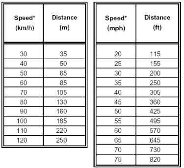
31. Page 6F-1, Section 6F.01. Types of Devices. Under Guidance, change: “…all road users.” To: “…all road users (drivers, pedestrians, and bicyclists).”; under Standard, change: “…or guide traffic…” to: “…or guide road users…”.
32. Page 6F-2, Section 6F.02. General Characteristics of Signs. Under the first Standard, change: “…a black legend on an orange background…” to: “…a black legend and border on an orange background…”; chang:e “Railroad Advance Warning (W10-1) sign: to: “Highway-Rail Grade Crossing Advance Warning (W10-1) sign”; change: “…a black message and border on a yellow…” to: “…a black legend and border on a yellow…”; change: “…in Part 2 to have yellow or fluorescent yellow-green backgrounds…” to: “…in Parts 2 or 7 to have fluorescent yellow-green backgrounds…”; under the first Option, insert a new first paragraph: “Warning and guide signs used for temporary traffic control incident management situations (see Chapter 6I) may have a black legend and border on a fluorescent coral background.”
33. Page 6F-3, Section 6F.03. Sign Placement. Under the Standard, change: “…parking and/or pedestrian…” to: “…parking and/or bicycle or pedestrian…”; insert a new third paragraph: “Signs shall be mounted and placed in accordance with Section 4.4 of the “Americans with Disabilities Act Accessibility Guidelines (ADAAG)” (see Section 1A.11).”; under the second Guidance, change: “bicycle lanes” to: “bicycle facilities” and add a new second sentence: “Signs mounted lower than 2.1 m (7 ft) should not project more than 100 mm (4 in) into pedestrian facilities.”
34. Page 6F-4, Figure 6F-1. In the metric version of the Advisory Speed Plaque, add a black circle around the “60”.
35.
Page 6F-5, Section 6F.03. Sign Placement. Under
the second Option, change: “…or other similar type signs maybe used…” to: “…or
other similar type signs (see Figures 6F-4, 6F-5, 6F-6, and 6F-12) may be
used…” Following the third Option,
insert new paragraphs:
Support:
The design and placement of work zone signs is described elsewhere in Chapter 6F of this Manual.
Guidance:
Sign posts placed in the clear zone should yield or breakaway upon impact to minimize obstructions to road users and to not present an undue risk to workers.
Support:
Depending upon the crash tested design, slight variations to the support might not be considered crashworthy.
Option:
Although work zone signs may be mounted on fixed, temporary, or portable supports, fixed supports are preferable for long-term projects.
Guidance:
These supports should meet the breakaway requirements for permanent installations discussed in AASHTO’s “Roadside Design Guide” (see Section 1A.11).
Option:
Generally
sign supports that are approved for use with longer-term signs may also be used
for shorter-term signs.
36. Page 6F-7, Section 6F.05. Regulatory Sign Authority. Under Support, change: “Regulatory signs inform…” to: “Regulatory signs such as those shown in Figures 6F-3 through 6F-5 inform…”
37. Page 6F-7, Section 6F.06. Regulatory Sign Design. Change:
Support:
Temporary traffic control regulatory signs shall conform to the Standards for regulatory signs presented in Part 2 and in FHWA’s "Standard Highway Signs" book. Regulatory signs are generally rectangular with a black legend and border on a white background. Exceptions include the STOP, YIELD, DO NOT ENTER, WRONG WAY, and ONE WAY signs.
to:
Standard:
Temporary traffic control regulatory signs shall conform to the Standards for regulatory signs presented in Part 2 and in the FHWA’s "Standard Highway Signs" book.
Support:
Regulatory signs are generally rectangular with a black legend and border on a white background. Exceptions include the STOP, YIELD, DO NOT ENTER, WRONG WAY, and ONE WAY signs.
38. Page 6F-8. Add a Figure number and title to this page of sign images: “Figure 6F-3. Regulatory Signs in Temporary Traffic Control Zones”; change the design and size of the metric version of the R2-1 sign to conform to the proposed change in Part 2; add a FINES HIGHER sign designated as R2-6 with a size of 600 mm x 600 mm (24 in x 24 in); delete the R2-5a, R2-5b (both versions), and R2-5c signs; and add a symbolic combined No Left Turn/No U Turn sign designated as R3-18 with a size of 600 mm x 600 mm (24 in x 24 in).
39. Page 6F-9. Add a Figure number and title to this page of sign images: “Figure 6F-4. Additional Regulatory Signs in Temporary Traffic Control Zones”; change the sizes of the R9-8 sign from “600 x 300 mm (24 x 12 in)” to “900 x 450 mm (36 x 18 in)”; change the size of the R9-9 sign from “600 x 300 mm (24 x 12 in)” to: “750 x 450 mm (30 x 18 in)”; change the size of the R9-10 sign from “600 x 300 mm (24 x 12 in)” to “1200 x 600 mm (48 x 24 in)”; change the size of the R9-11 sign from “600 x 300 mm (24 x 12 in)” to “1200 x 900 mm (48 x 36 in)”; and change the size of the R9-11a sign from “600 x 300 mm (24 x 12 in)” to “1200 x 600 mm (48 x 24 in)”.
40. Page 6F-10. Add a Figure number and title to this page of sign images: “Figure 6F-5. Additional Regulatory Signs for Road Closure and Weight Limits in Temporary Traffic Control Zones”.
41. Page 6F-11, Section 6F.08. ROAD (STREET) CLOSED Sign (R11-2). Under the first Guidance, change: “…(R11-2) sign should be used…” to: “…(R11-2) sign (see Figure 6F-4) should be used…”.
42. Page 6F-11, Section 6F.09. Local Traffic Only Signs (R11-3a, R11-4). Under the Guidance, change: “…signs should be used…” to: “…signs (see Figure 6F-5) should be used…”
43. Page 6F-12, Section 6F.10. Weight Limit Signs (R12-1, R12-2, R12-5). In the first paragraph change: “A Weight Limit sign, which…” to: “A Weight Limit sign (see Figure 6F-5), which…”; in the second paragraph, change: “…imposed, a marked detour…” to: “…imposed because of the activity in a temporary traffic control zone, a marked detour…”
44. Page 6F-12, Section 6F.11. STAY IN LANE Sign (R4-9). Change: “…sign may be used…” to: “…sign (see Figure 6F-4) may be used…”
45. Page 6F-12, Section 6F.12. PEDESTRIAN CROSSWALK Sign (R9-8). Change: “…sign may be used…” to: “…sign (see Figure 6F-4) may be used…”; after the Option insert:
Standard:
If a temporary crosswalk is established, it shall be accessible to pedestrians with disabilities.
46. Page 6F-12, Section 6F.13. SIDEWALK CLOSED Signs (R9-9, R9-10, R9-11, R9-11a). Under Guidance, in the first paragraph, change: “SIDEWALK CLOSED signs should be used where pedestrian flow is restricted or rerouted by work activities.” To: “SIDEWALK CLOSED signs (see Figure 6F-4) should be used where pedestrian flow is restricted. Bicycle/Pedestrian Detour (M4-9a) signs or Pedestrian Detour (M4-9b) signs should be used where pedestrian flow is rerouted (see Section 6F.50).”
47. Page 6F-13, Section 6F.13. SIDEWALK CLOSED Signs (R9-9, R9-10, R9-11, R9-11a). Under Support, change: “These signs are typically mounted on a barricade to encourage compliance.” to: “These signs are typically mounted on a detectable barricade to encourage compliance and to communicate with pedestrians that the sidewalk is closed. Printed signs are not useful to many pedestrians with visual disabilities. Accessible pedestrian signals (see Section 4E.06) can provide audible information about traffic signal phasing at alternate routes.”
48. Page 6F-13, Section 6F.14. Special Regulatory Signs. Following Guidance, insert a support statement that reads: “Section 2B.15 contains information regarding the use of FINES HIGHER signs (see Figure 2B-1).”
49. Page 6F-13, Section 6F.15. Warning Sign Function, Design, and Application. Under the Support, change: “…warning signs notify…” to: “…warning signs (see Figures 6F-6 through 6F-12) notify…”; under the Standard, change: “…black symbol or message and border…” to: “…black legend and border…”; change: “…black message and border on a yellow background…” to: “…black legend and border on a yellow background…”; change: “…in Part 2 to have yellow or fluorescent…” to: “…in Parts 2 or 7 to have fluorescent…”; under the Option, insert a new first paragraph: “Warning signs used for temporary traffic control incident management situations may have a black legend and border on a fluorescent coral background.”; and in the existing second paragraph (new third paragraph of the Option, change: “…if orange signs are…” to: “…if signs with orange or fluorescent coral backgrounds are…”
50. Page 6F-14. Add a figure number and title to this page of sign images: “Figure 6F-6. Warning Signs in Temporary Traffic Control Zones”; remove the border from the W1-8 sign; add two versions of the W3-5 signs and two versions of the W3-5a signs, all with the size of 900 x 900 mm (36 x 36 in); change the design of the W4-2 sign to include a vertical solid lane line and change its size from “900 x 900 mm (36 x 36 in)” to “1200 x 1200 mm (48 x 48 in)”; and remove the W5-1 sign and its size note from this page.
51. Page 6F-15. Add a figure number and title to this page of sign images: “Figure 6F-7. Warning Signs in Temporary Traffic Control Zones”; add the W5-1 sign and its size note; reverse the positions of the W5-2 and W5-2a signs and change the designation of the W5-2a sign to “W5-1a”.
52. Page 6F-16. Add a figure number and title to this page of sign images: “Figure 6F-8. Warning Signs in Temporary Traffic Control Zones”; change the size of the W9-1 and W9-2 signs from “900 x 900 mm (36 x 36 in)” to “1200 x 1200 mm (48 x 48 in)”; add a new W11-10a symbolic dump truck warning sign with size of 900 x 900 mm (36 x 36 in); and on the metric version of the W13-1 sign add a black circle around the “60”.
53. Page 6F-17. Add a figure number and title to this page of sign images: “Figure 6F-9. Warning Signs in Temporary Traffic Control Zones”; in the two signs W20-5a, at lower right, change word placement so that “TWO LANES” is on one line only instead of on two lines.
54. Page 6F-18. Add a figure number and title to this page of sign images: “Figure 6F-10. Warning Signs in Temporary Traffic Control Zones”; change the illustration of the W20-7a sign to show the metric version of the supplemental distance plaque without the diamond shaped warning sign above it; and below the W20-7a sign change “SUPPLEMENTAL PLAQUE” to “W16-4”.
55. Page 6F-19. Add a figure number and title to this page of sign images: “Figure 6F-11. Warning and Guide Signs in Temporary Traffic Control Zones”; in the W22-2 sign change: the designation from “W22-2” to: “W22-2a” and change: “PHONE” to: “CELL PHONE”; change the W23-1 sign from a rectangle to a diamond shape and change the size from “1200 x 600 mm (48 x 24 in)” to “900 x 900 mm (36 x 36 in)’; add new W24-1a, W24-1b, and W24-1c signs with sizes for all of 900 x 900 mm (36 x 36 in); and change the sign designation of the END ROAD WORK sign from “G20-2a” to “G20-2”.
56. Page 6F-20. Add a figure number and title to this page of sign images: “Figure 6F-12. Exit Open and Closed and Detour Signs”; and add new M4-9a, M4-9b, and M4-9c signs with sizes for all of 750 x 600 mm (30 x 24 in).
57. Page
6F-21, Section 6F.15. Warning Sign
Function, Design, and Application.
Under Guidance, insert a new third paragraph: “Where road users include pedestrians, the provision of
supplemental audible or tactile warning information should be considered for
people with visual disabilities.”
58. Page
6F-22, Section 6F.16. Position of
Advance Warning Signs. Under
Guidance, change: “…road users are not confused…” to: “…road users (drivers,
bicyclists, and pedestrians) are not confused…”
59. Page
6F-22, Section 6F.17. ROAD (STREET)
WORK Sign (W20-1). Under Guidance,
change: “…sign, which…” to: “…sign (see Figure 6F-9), which…”; following
“taking place”, remove “and on all intersecting roadways”; and insert
following:
Option:
Where traffic can enter a temporary traffic control zone from a crossroad or a major (high-volume) driveway, an advance warning sign may be used on the crossroad or major driveway.
60. Page 6F-22, Section 6F.18. DETOUR Sign (W20-2). Under Guidance, change: “…sign should…” to: “…sign (see Figure 6F-9) should…”
61. Page 6F-23, Section 6F.20. ONE LANE ROAD Sign (W20-4). Under Standard, in the first paragraph, change: “The LANE(S) CLOSED sign shall…” to: “…The LANE(S) CLOSED sign (see Figure 6F-9) shall…”; in the second paragraph in the first sentence, change: “For a single lane closure, the LANE CLOSED (W20-5) sign shall…” to: “For a single lane closure, the LANE CLOSED (W20-5) sign (see Figure 6F-9) shall…” and in the second sentence, change: “Where two adjacent lanes are closed, the W20-5a sign shall…” to: “Where two adjacent lanes are closed, the W20-5a sign (see Figure 6F-9) shall…”
62. Page 6F-23, Section 6F.21. LANE(S) CLOSED Signs (W20-5, W20-5a). Under Standard, in the first paragraph, change: “…sign shall…” to: “…sign (see Figure 6F-9) shall…”; in the second paragraph, change: “…the sign shall…” to: “…the W20-5a sign shall…”
63. Page 6F-24, Section 6F.22. CENTER LANE CLOSED AHEAD Signs (W9-3, W9-3a). Under Guidance, change: “…sign should…” to: “…sign (see Figure 6F-8) should…”; under Option, change: “…sign may…” to: “…sign (see Figure 6H-38) may…”
64. Page 6F-24, Section 6F.23. THRU TRAFFIC MERGE RIGHT (LEFT) Sign (W4-1a). In the Section title and twice under Guidance, change: “RIGHT (LEFT)” to: “LEFT (RIGHT)”; change: “motor vehicle” to: “vehicular”.
65. Page 6F-24, Section 6F.24. Lane Reduction Sign (W4-2). In the Section title and under Option, replace “Reduction” with “Ends”; change: “…sign may…” to: “…sign (see Figure 6F-6) may…”; change: “motor vehicle” to: vehicular”.
66. Page 6F-24, Section 6F.25. ON RAMP Plaque (W13-4). Change: “…plaque should…” to: “…plaque (see Figure 6F-8) should…”
67. Page 6F-24, Section 6F.26. RAMP NARROWS Sign (W5-4). Change: “…sign should…” to: “…sign (see Figure 6F-7) should…”
68. Page 6F-25, Section 6F.27. SLOW TRAFFIC AHEAD Sign (W23-1). Change: “…sign may…” to: “…sign (see Figure 6F-11) may…”
69. Page 6F-25, Section 6F.28. EXIT OPEN, EXIT CLOSED Signs (E5-2, E5-2a). Change: “…sign may…” to: “…sign (see Figure 6F-12) may…”; following the Option, insert:
Guidance:
When an exit ramp is closed, an EXIT CLOSED panel with a black legend and border on an orange background should be placed diagonally across the interchange/intersection guide signs.
70. Page 6F-25, Section 6F.29. Flagger Sign (W20-7, W20-7a). Change Section title to: “…(W20-7a, W20-7)”; under Guidance, change: “sign should” to: “sign (see Figure 6F-10) should”; under Option, change: “…(W20-7b) sign.” to: “…(W20-7b) sign (see Figure 6F-10)”.
71. Page 6F-25, Section 6F.30. Two-Way Traffic Sign (W6-3). Under Guidance, change: “…sign should…” to: “…sign (see Figure 6F-7) should…”; in lines one, three and four, change: “motor vehicle” to: “vehicular”.
72. Pages 6F-26, Section 6F.31. Workers Sign (W21-1, W21-1a). Under Option, change: “…sign may…” to: “…sign (see Figure 6F-10) may…”
73. Pages 6F-26, Section 6F.32. FRESH OIL (TAR) Sign (W21-2). Change: “…sign should…” to: “…sign (see Figure 6F-10) should…”
74. Pages 6F-26, Section 6F.33. ROAD MACHINERY AHEAD Sign (W21-3). Change: “…sign may…” to: “…sign (see Figure 6F-10) may…”
75. Pages 6F-26, Section 6F.34. SHOULDER WORK Signs (W21-5, W21-5a, W21-5b). Change Section title to: “Section 6F.34 Shoulder Work Signs (W21-5, W21-5a, W21-5b)”; change: “…signs warn…” to: “…signs (see Figure 6F-10) warn…”
76. Page 6F-27, Section 6F.35. SURVEY CREW Sign (W21-6). Change: “…sign should…” to: “…sign (see Figure 6F-10) should…”
77. Page 6F-27, Section 6F.36. UTILITY WORK Sign (W21-7). Change: “…sign may…” to: “…sign (see Figure 6F-11) may…”
78. Page 6F-28, Section 6F.37. Signs for Blasting Areas. Under Support, change: “…in work zones.” To: “…in temporary traffic control zones.”
79. Page 6F-28, Section 6F.38. BLASTING ZONE AHEAD Sign (W22-1). Change: “…sign shall…” to: “…sign (see Figure 6F-11) shall…”; change: “RADIO AND PHONE” to: “RADIO AND CELL PHONE”.
80. Page 6F-28, Section 6F.39. TURN OFF 2-WAY RADIO AND PHONE Sign (W22-2). Change Section title to: “Section 6F.39 TURN OFF 2-WAY RADIO AND CELL PHONE Sign (W22-2)”. Under the Standard, change: “RADIO AND PHONE” to: “RADIO AND CELL PHONE”; change: “…sign shall…” to: “…sign (see Figure 6F-11) shall…”
81. Page 6F-29, Section 6F.40. END BLASTING ZONE Sign (W22-3). Under Standard, change: “…sign shall…” to: “…sign (see Figure 6F-11) shall…”
82. Page 6F-29, Section 6F.41. SHOULDER DROP-OFF Sign (W8-9). Change the Section title to: “Section 6F.41 Shoulder and UNEVEN LANES Signs (W8-4, W8-9, W8-9a, and W8-11)”; before the Standard insert:
Option:
The SOFT SHOULDER (W8-4) sign (see Figure 6F-7) may be used to warn of a soft shoulder condition.
The LOW SHOULDER (W8-9) sign (see Figure 6F-7) may be used to warn of a shoulder condition where there is an elevation difference of less than 75 mm (3 in) between the shoulder and the travel lane.
Under the Standard, change: “…sign shall…” to: “…sign (see Figure 6F-7) shall…”
83. Page
6F-29, Section 6F.42. UNEVEN LANES Sign
(W8-11). Remove the Section number
and title so that this Guidance
concludes Section 6F.41; change: “…sign should…” to: “…sign (see Figure 6F-8)
should…”; change: “…a difference…” to: “…a substantial difference…”
84. Page 6F-29, Section 6F.43. NO CENTER STRIPE Sign (W8-12). Change the Section number to: “Section 6F.42”; change: “…(W8-12) sign…” to: “…(W8-12) sign (see Figure 6F-8)…”
85. Page 6F-29. After existing Section 6F.43 (new Section 6F.42) insert a new Section numbered and titled: “Section 6F.43. Double Reverse Curve Signs (W24 Series)”. The new Section reads:
Option:
The Double Reverse Curve (W24-1a, W24-1b, or W24-1c) sign (see Figure 6F-11) may be used when the tangent distance between two reverse curves is insufficient for a second Reverse Curve (W1-4 Series) sign to be placed between the curves.
Standard:
If a Double Reverse Curve sign is
used, the number of lanes illustrated on the sign shall be the same as the
number of through lanes available to road users, and the direction of the
double reverse curve shall be appropriately illustrated.
86. Page 6F-30, Section 6F.44. Other Warning Signs. Under Standard, change: “…Railroad Advance Warning (W10-1) sign…” to: “…Highway-Rail Grade Crossing Advance Warning sign (W10-1)…”; change: “…sign, and school…” to: “…sign (see Figure 6F-8), and school.”
87. Page 6F-30, Section 6F.45. Advisory Speed Plaque (W-13-1). Change: “…plaque may…” to: “…plaque (see Figure 6F-8) may…”
88. Page 6F-31, Section 6F.47. Guide Signs. Under Standard, change: “…legend on…” to: “…legend and border on…”; under Option, insert a new first paragraph: “Guide signs used in temporary traffic control incident management situations may have a black legend and border on a fluorescent coral background.”; under Option, in the existing paragraph (new second paragraph) change: “…legend on…” to: “…legend and border on…”
89. Page 6F-32, Section 6F.48. ROAD WORK NEXT XX KM (MILES) Sign (G20-1). Under Guidance, change: “…sign should…” to: “…sign (see Figure 6F-11) should…”; under Option, change: “…for work zones…” to: “…for temporary traffic control zones…”
90. Page 6F-32, Section 6F.49. END ROAD WORK Sign (G20-2a). Change Section title to: “Section 6F.49 END ROAD WORK Sign (G20-2)”. Under Guidance, change: “The END ROAD WORK (G20-2a) sign should be placed about 150 m (500 ft) beyond the temporary traffic control zone.” To: “The END ROAD WORK (G20-2) should be placed at the end of the termination area.”
91. Page 6F-32, Section 6F.50. Detour Signs and Markers (M4-8, M4-8a, M4-8b, M4-9, and M4-10). Change the Section title to: “Section 6F.50 Detour Signs and Markers (M4-8, M4-8a, M4-8b, M4-9, M4-9a, M4-9b, M4-9c, and M4-10)”; under the Option, insert a new first paragraph: “Detour signs and markers in temporary traffic control incident management situations may have a black legend and border on a fluorescent coral background.”; in the existing first paragraph (new second paragraph) of the Option, change: “…sign may…” to: “…sign (see Figure 6F-12) may…”; in the existing second paragraph (new third paragraph), change: “…marker may…” to: “…marker (see Figure 6F-12) may…”
92. Page 6F-33, Section 6F.50. Detour Signs and Markers (M4-8, M4-8a, M4-8b, M4-9, and M4-10). Under the first Guidance, in the second paragraph, change: “…sign should…” to: “…sign (see Figure 6F-12) should…”; under Option, change: “…sign may be used…” to: “…sign (see Figure 6F-12) may be used…”; after the second Guidance, insert the following:
Standard:
The Pedestrian/Bicycle Detour (M4-9a) sign (see Figure 6F-12) shall be used where a pedestrian/bicycle detour route has been established because of the closing of a pedestrian/bicycle facility to through traffic.
If used, the Pedestrian/Bicycle Detour sign shall have an arrow pointing in the appropriate direction.
Option:
The arrow may be on the sign face of on a supplemental plaque.
The Pedestrian Detour M4-9b) sign or Bicycle Detour (M4-94c) sign (see Figure 6F-12) may be used where a pedestrian or bicycle detour route (not both) has been established because of the closing of that particular facility to through traffic.
93. Page 6F-33, Section 6F.51. PILOT CAR FOLLOW ME Sign (G20-4). Under the Standard, change: “…sign shall…” to: “…sign (see Figure 6F-11) shall…”; in the third and fourth lines, change “motor vehicle” to “vehicular”.
94. Page 6F-33, Section 6F.52. Portable Changeable Message Signs. In the Standard, in the third line, change: “Typically, a phase…” to: “A phase…”; add a new fourth sentence to the Standard: “Each character module shall use at least a five wide and seven high pixel matrix.”
95. Page 6F-34, Section 6F.52. Portable Changeable Message Signs. Under Guidance, change: “Portable Changeable Message signs should subscribe to the principles established in this Manual…” to: “Portable Changeable Message signs should subscribe to the principles established in Section 2A.07 and other sections of this Manual…”; change the fourth paragraph from:
Portable Changeable Message signs should be visible from 0.8 km (0.5 mi) under both day and night conditions. The message should be legible from a minimum distance of 200 m (650 ft). The message panel should have adjustable display rates, so that the entire message can be read at least twice at the posted speed, the off-peak 85th-percentile speed prior to work starting, or the anticipated operating speed.
to:
Portable Changeable Message signs should be visible from 0.8 km (0.5 mi) under both day and night conditions. For a trailer or large truck mounted sign, the letter height should be a minimum of 450 mm (18 in). For Changeable Message signs mounted on service patrol trucks, the letter height should be a minimum of 250 mm (10 in).
The message panel should have adjustable display rates (minimum of 3 seconds per phase), so that the entire message can be read at least twice at the posted speed, the off-peak 85th-percentile speed prior to work starting, or the anticipated operating speed.
Messages should be designed taking into account the following factors:
A. Each phase should convey a single thought.
B. If the message can be displayed in one phase, the top line should present the problem, the center line should present the location or distance ahead, and the bottom line should present the recommended driver action.
C. The message should be as brief as possible.
D. When a message is longer than two phases, additional Portable Changeable Message signs should be used.
E. When abbreviations are used, they should be easily understood (see Section 1A.14)”;
Under Option, following the first paragraph, insert two new paragraphs:
Smaller letter sizes may be used on a Portable Changeable Message sign mounted on a trailer or large truck provided that the message is legible from at least 200 m (650 ft), or mounted on a service patrol truck provided that the message is legible from at least 100 m (330 ft).
Two Portable Changeable Message signs may be used for the purpose of allowing the entire message to be read twice at the posted speed.
Under Standard, in the fourth paragraph, change: “The mounting of Portable Changeable Message signs shall be such that the bottom of the message sign panel shall be a minimum of 2.1 m (7 ft) above the roadway when it is in the operating mode.” to: “The mounting of Portable Changeable Message signs on a trailer, a large truck, or a service patrol truck shall be such that the bottom of the message sign panel shall be a minimum of 2.1 m (7 ft) above the roadway in urban areas and 1.5 m (5 ft) above the roadway in rural areas when it is in the operating mode.”
96. Page 6F-35, Section 6F.52. Portable Changeable Message Signs. Under Support, change: “…roadway, lane, or ramp closures, crash or emergency incident management, width restriction information, speed reductions…,” to: “…roadway, lane, or ramp closures, crash or emergency incident management, width restriction information, speed control or reductions…”; change: “…and diversion, warning of adverse conditions, and operation control.” to : “…and diversion, warning of adverse conditions or special events, and other operational control.” under second Support, listed item A, change: “motor vehicle” to: “vehicular”.
97. Pages 6F-35 and 6F-36, Section 6F.52. Portable Changeable Message Signs. Under the second Guidance, in the first paragraph, change: “When Portable Changeable Message signs are used for route diversion, they should be placed far enough in advance of the diversion to allow road users ample opportunity to exit the affected highway.” to: “When Portable Changeable Message signs are used for route diversion, they should be placed far enough in advance of the diversion to allow road users ample opportunity to perform necessary lane changes, to adjust their speed, or to exit the affected highway”; remove (due to relocation to page 6F-34) the following:
Messages should be designed taking into account the following factors:
A. Each phase should convey a single thought.
B. If the message can be displayed in one phase, the top line should present the problem, the center line should present the location or distance ahead, and the bottom line should present the recommended driver action.
C. The message should be as brief as possible.
D. When a message is longer than two phases, additional Portable Changeable Message signs should be used.
E. When abbreviations are used, they should be easily understood (see Section 1A.14).
98. Page 6F-36, Section 6F.53. Arrow Panels. Under Guidance, insert a new first paragraph:
An arrow panel in the arrow mode should be used to advise approaching traffic of a lane closure along major multilane roadways in situations involving heavy traffic volumes, high speeds, and/or limited sight distances, or at other locations and under other conditions where road users are less likely to expect such lane closures.
In the existing first paragraph (new second paragraph) of the Guidance, change: “An arrow panel should…” to: “If used, an arrow panel should…”; in the existing second (new third) paragraph of Guidance, in the second sentence, remove: “…or when within the clear zone, shielded with a barrier or crash cushion.”
99. Page 6F-37, Section 6F.53, Arrow Panels. Under the first Standard, change “…Figure 6F-3.” to “…Figure 6F-13.”
100. Page 6F-38, Figure 6F-3, Advance Warning Arrow Display Specifications. Change the figure number to: “Figure 6F-13”.
101. Page 6F-39, Section 6F.53, Arrow Panels. Under the first Standard, third paragraph, change: “An arrow panel shall be used only in the caution mode for shoulder work, blocking the shoulder, for roadside work near the shoulder, or for temporarily closing one lane on a two-lane, two-way roadway.” To: “For shoulder work, blocking the shoulder, for roadside work near the shoulder, or for temporarily closing one lane on a two-lane, two-way roadway, an arrow panel shall be used only in the caution mode.”
102. Page 6F-40, Section 6F.53, Arrow Panels. After the Standard (at the conclusion of the Section), add a final Option: “A portable changeable message sign may be used to simulate an arrow panel display.”
103. Page 6F-41, Section 6F.55. Channelizing Devices. Under the first Standard, change “…Figure 6F-4.” to “…Figure 6F-14.”; under Support, in the first paragraph, change: “…users of conditions…” to: “…users (drivers, bicyclists, and pedestrians) of conditions…”; in the second paragraph, lines 1, 3, and 4, change: “motor vehicle” to: “vehicular”; at the conclusion of the Support, insert the following:
Standard:
Devices used to channelize pedestrians shall be detectable to users of long
canes. The pedestrian passage shall be accessible per the Americans with
Disabilities Act of 1990 (ADA), Title II, paragraph 35.151.
Where barricades are used to channelize pedestrians, there shall be continuous
detectable bottom and top rails with no gaps between individual barricades to be
detectable to users long canes. The bottom of the bottom rail shall be no higher
than 150 mm (6 in) above the ground surface. The top of the top rail shall be no
lower than 915 mm (36 in) above the ground surface.
Guidance:
A 38 mm (1 ½ in) gap between the bottom rail and the ground surface may be
Used to facilitate drainage.
Standard:
Where drums, cones, or tubular markers are used to channelize pedestrians, they shall be located such that there are no gaps between the bases of the devices, in
order to create a continuous bottom, and the height of each individual drum, cone,
or tubular marker shall be no less than 915 mm (36 in) to be detectable to users of
long canes.
Under Guidance, first paragraph, remove “in the immediate area”; in the third paragraph, lines 1 and 2, change: “motor vehicle” to: “vehicular”; under the second Standard, in the second paragraph, change: “…display approximately the same color…” to: “…display a similar color…”
104. Pages 6F-42 and -43, Figure 6F-4, Sheets 1 and 2. Channelizing Devices. Change the figure number on both sheets to: “Figure 6F-14”; on Page 6F-42, beneath the illustration “Vertical Panel,” replace three asterisks with two asterisks and insert a dimension from the bottom of the panel to the ground: “300 mm (12 in) MAX.”; in the illustration “Drum”, beneath “(36 in)” insert “MIN.”; in the illustration “Tubular Markers,” beneath “(28 in)” at left, insert “MIN.” and beneath “(18 in)” at center, insert “MIN.”; in the illustration “Cones,” beneath “(28 in)” at left, insert “MIN.” and beneath “(18 in)” at right, insert “MIN.”; in the footnotes at bottom of page, delete the second note that begins with two asterisks; in the note following the latter deletion, replace the three asterisks with two asterisks and add to the bottom of the figure:
Note: Where drums, cones, or tubular markers are used to channelize pedestrians, they shall be located such that there are no gaps between the bases of the devices, in order to create a continuous bottom, and the height of each individual drum, cone, or tubular marker shall be no less than 915 mm (36 in), to be detectable to users of long canes.
On Page 6F-43, in the illustrations “Type I Barricade,” “Type II Barricade,” and “Type III Barricade,” delete the two asterisks from the right side of each illustration, and in each illustration caption, change three asterisks to two asterisks; between the illustration “Direction Indicator Barricade” and its caption, insert a two-headed arrow and the callout “45 degrees”; in the footnotes at the bottom of the figure, delete the second note that begins with two asterisks; in the note following the latter deletion, replace the three asterisks with two asterisks; and at the bottom of page 6F-43 add:
Note: Where barricades are used to channelize pedestrians, there shall be continuous detectable bottom and top rails with no gaps between individual barricades, to be detectable to users of long canes. The bottom of the bottom rail shall be no higher than 150 m (6 in) above the ground surface. The top of the top rail shall be no lower than 915 mm (36 in) above the ground surface.
105. Page 6F-44, Section 6F.56. Cones. Under Standard, first paragraph, change “…(see Figure 6F-4)….” to “…(see Figure 6F-14)…”; change the second paragraph from:
For nighttime use, cones shall be retroreflectorized or equipped with lighting devices for maximum visibility. Retroreflectorization of 700 mm (28 in) or larger cones shall be provided by a white band 150 mm (6 in) wide located 75 to 100 mm (3 to 4 in) from the top of the cone and an additional 100 mm (4 in) wide white band approximately 50 mm (2 in) below the 150 mm (6 in) band.
to:
For nighttime use, cones shall be retroreflectorized or equipped with lighting devices for maximum visibility. Retroreflectorization of cones that are 700 to 900 mm (28 to 36 in) in height shall be provided by a 150 mm (6 in) wide white band located 75 to 100 mm (3 to 4 in) from the top of the cone and an additional 100 mm (4 in) wide white band located approximately 50 mm (2 in) below the 150 mm (6 in) band.
Following the second paragraph of the Standard, insert a new paragraph:
Retroreflectorization of cones that are more than 900 mm (36 in) in height shall be provided by horizontal, circumferential, alternating orange and white retroreflective stripes that are 100 to 150 mm (4 to 6 in) wide. Each cone shall have a minimum of two orange and two white stripes with the top stripe being orange. Any nonretroreflective spaces between the orange and white stripes shall not exceed 75 mm (3 in) in width”;
Under Option, change: “motor vehicle” to: “vehicular”.
106. Page 6F-45, Section 6F.56. Cones. Under first Guidance, first paragraph, change: “motor vehicle” to: “vehicular”; following first paragraph, insert a new second paragraph:
Cones should not be used for pedestrian channelization or as pedestrian barriers in temporary traffic control zones on or along sidewalks unless they are continuous between individual devices and detectable to users of long canes.
107. Page 6F-45, Section 6F.57. Tubular Markers. Under Standard, change “…(see Figure 6F-4)…” to “…(see Figure 6F-14)…”; under Guidance, insert a new first paragraph:
Tubular markers should not be used for pedestrian channelization or as pedestrian barriers in temporary traffic control zones on or along sidewalks unless they are continuous between individual devices and detectable to users of long canes.
108. Page 6F-46, Section 6F.57. Tubular Markers. Under Option, change: “motor vehicle” to: “vehicular”.
109. Page 6F-46, Section 6F.58. Vertical Panels. Under the first Standard, first paragraph, change: “Vertical panels (see Figure 6F-4) shall…” to: “Vertical panels (see Figure 6F-14 Sheet 1) shall…”; in second paragraph, change:
Vertical panels shall be mounted with the top a minimum of 900 mm (36 in) above the roadway.
to:
Vertical panels shall be mounted with the top a minimum of 900 mm (36 in) above the roadway, and a minimum of 1050 mm (42 in) above the pedestrian travel way. Vertical panels shall be mounted with the bottom no greater than 300 mm (12 in) above the ground.
Under second Standard, lines 3 and 5, change: “motor vehicle” to: “vehicular”.
110. Page 6F-47, Section 6F.58, Vertical Panels. Under Option, change: “motor vehicle” to: “vehicular”.
111. Page 6F-47, Section 6F.59. Drums. Under the first Standard, change: “Drums (see Figure 6F-4) used for…” to “Drums (see Figure 6F-14 Sheet 1) used for…”; remove the comma from “white stripes, shall not exceed”; under Guidance, insert a new first paragraph:
Drums should not be used for pedestrian channelization or as pedestrian barriers in temporary traffic control zones on or along sidewalks unless they are continuous between individual devices and detectable to users of long canes.
112. Page 6F-48, Section 6F.60. Type I, II, or III Barricades. Under Support, in the second paragraph, change: “As shown in Figure 6F-4…” to “As shown in Figure 6F-14 Sheet 2…”; following Guidance, insert a new third Standard:
Standard:
Supports shall not project into circulation routes more than 100 mm (4 in) from the support between 675 mm (27 in) and 2000 mm (80 in) from the surface as described in Section 4.4.1 of the “Americans with Disabilities Act Accessibility Guidelines (ADAAG)” (see Section 1A.11). Supports shall not narrow the pedestrian facility to less than 1200 mm (48 in), with a 1500 mm x 1500 mm (60 in x 60 in) passing space at least every 60m (200 ft), as described in Section 4.3.4 of the “Americans with Disabilities Act Accessibility Guidelines (ADAAG)” (see Section 1A.11).
113. Page 6F-49, Section 6F.60. Type I, II, or III Barricades. Under the first Guidance, change: “motor vehicle” to: “vehicular”; under Standard, change: “…chunks of concrete.” to: “…chunks of concrete. Ballast shall not extend into the accessible passage width of 1500 mm (60 in).”
114. Page 6F-50, Section 6F.61, Direction Indicator Barricades. Under Standard, change: “…(see Figure 6F-4)…” to “…(see Figure 6F-14)…”; under Guidance, change: “The Direction Indicator Barricade should be crashworthy.” to: “The Direction Indicator Barricade, including any associated ballast or lights, should be crashworthy.”
115. Page 6F-51, Section 6F.62, Temporary Traffic Barriers as Channelizing Devices. After the Section title, before the Standard, insert:
Support:
Temporary traffic barriers are not temporary traffic control devices in themselves; however, when placed in a position identical to a line of channelizing devices and marked and/or equipped with appropriate channelization features to provide guidance and warning both day and night, they serve as temporary traffic control devices.
Standard:
Temporary traffic barriers serving as temporary traffic control devices shall conform to requirements for such devices as set forth throughout Part 6.
Under the existing first (new second) Standard, following “work space.”, insert “(see Section 6F-77).
116. Page 6F-51. Following Section 6F.62, insert a new section numbered and titled: “Section 6F.63 Longitudinal Channelizing Barricades” The new section reads:
Support:
Longitudinal channelizing barricades are lightweight, deformable channelizing devices that can be used singly as Type I, II, or III barricades, or connected so they are highly visible and have good target value. They are portable enough to be shifted from place to place within a site in order to accommodate changing conditions.
Option:
Longitudinal channelizing barricades may be used instead of a line of cones, drums, or barricades.
Longitudinal channelizing barricades may be hollow and filled with water as a ballast.
Guidance:
If used, longitudinal channelizing barricades should be interlocked to delineate or channelize flow including pedestrian traffic control. The interlocking barricade wall should not have gaps that allow pedestrians or vehicles to stray from the channelizing path.
Support:
Longitudinal channelizing barricades are often located adjacent to traffic and therefore are subject to impact by errant vehicles.
Guidance:
Because of their vulnerable position, longitudinal channelizing barricades should be constructed of lightweight materials and be crashworthy.
Although longitudinal channelizing barricades might give the appearance of being formidable obstacles, they have not met the crashworthy requirements for temporary traffic barriers and, therefore, should not be used to shield pedestrians, including workers, from vehicle impacts or obstacles.
Option:
Longitudinal channelizing barricades may be suitable as pedestrian barriers.”
Then, insert a new Section numbered and titled “Section 6F.64 Other Channelizing Devices”. The new Section reads:
Option:
Channelizing devices other than those described in this Chapter may be used in special situations based on an engineering study.
Guidance:
Other channelizing devices should conform to the general size, color, stripe pattern, retroreflection, and placement characteristics established for the devices described in this Chapter.
117. Page 6F-51, Section 6F.63, Temporary Raised Islands. Change the Section number to: “Section 6F.65”; under Option, lines 1, 2, 3, and 6, change: “motor vehicle” to: “vehicular”.
118. Page 6F-52, Section 6F.63, Temporary Raised Islands. Under Guidance, change: “…by 450 mm…” to: “…by at least 450 mm…”; change: “…driver to lose control…” to: “…driver or bicyclist to lose control…”; following Guidance, insert a new paragraph:
Standard:
At pedestrian crossing locations, temporary raised islands shall have an opening or be shortened to provide at least a 1500 mm (60 in) wide pathway for the crossing pedestrian.
119. Page 6F-52, Section 6F.64, Opposing Traffic Lane Divider. Change the Section number to: “Section 6F.66”; under Support, change: “motor vehicle” to: “vehicular”; under Standard, insert a new first paragraph: “Opposing traffic lane dividers shall not be placed across pedestrian crossings.”; in the existing first (new second) paragraph of the Standard, change: “…sign is… “ to: “…sign (see Figure 6F-7) is…”
120. Page 6F-52, Section 6F.65, Pavement Markings. Change the Section number to: “Section 6F.67”; under Standard, second paragraph, change: “Section 6F.66.” to: “Section 6F.67.”; in the third paragraph, add a new third sentence: “Delineation and channelizing devices for use by pedestrians shall be accessible and detectable to pedestrians who have disabilities and shall be continuous throughout the temporary traffic control zone.”
121. Page 6F-53, Section 6F.65, Pavement Markings. Under Option, change: “…covered temporarily.” to: “…covered for a period of up to 2 weeks.”; following the Option, insert:
Support:
Pavement markings alone are generally not sufficient for use by pedestrians who have visual disabilities. Tactile warnings on the roadway surface or audible devices are usually more helpful to these pedestrians.
122. Page 6F-54, Section 6F.66, Temporary Pavement Markings. Change Section number to: “Section 6F. 68”
123. Page 6F-54, Section 6F.66, Temporary Pavement Markings. Under Option, change:
Half-cycle lengths with a minimum of 0.6 m (2 ft) stripes may be used
on roadways with severe curvature (see Section 3A.06). This applies to centerlines in passing zones and lane lines.
For temporary situations of 3 calendar days or less, for a two- or three-lane road, no-passing zones may be identified by using NO PASSING ZONE (W14-3) signs (see Section 2C.32) rather than pavement markings. Also, NO PASSING ZONE signs may be used instead of pavement markings on low-volume roads (as defined in Section 5A.01) for longer periods in accordance with the State's or highway agency's policy.
to:
Half-cycle lengths with a minimum of 0.6 m (2 ft) stripes may be used on roadways with severe curvature (see Section 3A.06) for centerlines in passing zones and for lane lines.
For temporary situations of 3 calendar days or less, for a two- or three-lane road, no-passing zones may be identified by using DO NOT PASS (R4-1) and PASS WITH CARE (R4-2) signs (see Sections 2B.24 and 2B.25) rather than pavement markings. Also, DO NOT PASS and PASS WITH CARE signs may be used instead of pavement markings on low-volume roads for longer periods in accordance with the State's or highway agency's policy.
Under Guidance, change: “The NO PASSING ZONE signs should be placed in accordance with Sections 2B.24, 2B.25, and 2C.32.” to: “If used, the DO NOT PASS and PASS WITH CARE signs should be placed in accordance with Sections 2B.24 and 2B.25.”
124. Page 6F-54, Section 6F.69, Raised Pavement Markers. Change the Section number to: “Section 6F.69”; under Standard, change:
If raised pavement markers are used to substitute for broken line segments, at least two retroreflective markers shall be placed, one at each end of a segment of 0.6 m (2 ft) to 1.5 m (5 ft). For segments over 1.5 m (5 ft), a group of at least three retroreflective markers shall be equally spaced at no greater than N/8. The value of N for a broken or dotted line shall equal the length of one line segment plus one gap. The value of N referenced for solid lines shall equal the N for the broken or dotted lines that may be adjacent to or may extend the solid lines (see Chapter 3B).
to:
If raised pavement markers are used to substitute for broken line segments, at least two retroreflective markers shall be placed, one at each end of a segment of 0.6 to 1.5 m (2 to 5 ft) in length. For segments longer than 1.5 m (5 ft), a group of at least three retroreflective markers shall be equally spaced at no greater than N/8 (see Section 3A.06). The value of N for a broken or dotted line shall equal the length of one line segment plus one gap. The value of N referenced for solid lines shall equal the N for the broken or dotted lines that might be adjacent to or might extend the solid lines (see Sections 3B.13 and 3B.14).
125. Page 6F-55, Section 6F.68, Delineators. Change the Section number to: “Section 6F.70”
126. Page 6F-55, Section 6F.69, Lighting Devices. Change the Section number to: “Section 6F-71”; under Guidance, insert the following as a new second paragraph: “The maximum spacing for warning lights should be identical to the channelizing device spacing requirements.”; following the Option, remove the heading “Support” and change “…beacons are adequately provided…” to “…beacons may be provided…”
127. Page 6F-56, Section 6F.69, Lighting Devices. Following the Standard, add a new Option: “Vehicle hazard warning signals may only supplement the rotating lights or strobe lights.”
128. Page 6F-56, Section 6F.70, Floodlights. Change the Section number to: “Section 6F.72”; under Support, change: “motor vehicle” to: “vehicular”; change: “…work.” to: “…work (see Section 6G.19).”; following the second Guidance, insert:
Support:
Research
indicates that 50 lux (5 foot candles) is a desirable nighttime illumination
level where workers are active.
129. Page 6F-56, Section 6F.71, Flashing Warning Beacons. Change the Section number to: “Section 6F.73”; under Support, change: “…temporary control device.” to: “…temporary traffic control device.”
130. Page 6F-57, Section 6F.72, Warning Lights. Change the Section number to: “Section 6F.74”; under the first Standard, change: “Type A, Type B, and Type C warning lights…” to: “Type A, Type B, Type C, and Type D 360-degree warning lights…”; under the second Standard, change: “…warning lights and Type C Steady-Burn warning lights shall be maintained…” to: “…warning lights, Type C Steady-Burn warning lights, and Type D 360-degree Steady-Burn warning lights shall be maintained…”
131. Page 6F-58, Section 6F.72, Warning Lights. Under the second Option, change: “…lights may…” to: “…lights and Type D 360-degree Steady-Burn warning lights may…”; under Guidance, change: “…Type C warning…” to: “…Type C and and Type D 360-degree warning…”
132. Page 6F-58, Section 6F.73, Steady-Burn Electric Lamps. Change the Section number to: “Section 6F.75”; under Option, change “…(see Section 6F.72).” to “…(see Section 6F.74).”
133. Page 6F-59, Section 6F.74, Temporary Traffic Control Signals. Change the Section number to: “Section 6F.76”; under the first Support, change: “…in work zones…” to: “…in temporary traffic control zones…”; under the second Standard, change: “motor vehicle” to: “vehicular”; in the first Guidance, insert a new first paragraph:
Where pedestrian traffic is detoured to a temporary traffic control signal, engineering judgment should be used to determine if pedestrian signals or accessible pedestrian signals (see Section 4E.06) are needed for crossing along an alternate route.
Between the Option and the second Guidance, insert a new third Standard:
Standard:
The supports for temporary traffic control signals shall not encroach into the minimum required pedestrian pathway width of 1500 mm (60 in).
Under the second Guidance, change: “motor vehicle” to: “vehicular”.
134. Page 6F-60, Section 6F.74, Temporary Traffic Control Signals. Under listed item C, change: “…road users…” to: “…road users, including bicyclists and pedestrians…”; insert a new item M: “The nature of adjacent land uses (such as residential or commercial)”; and change existing items M to N, N to O, O to P, P to Q, Q to R, R to S, S to T, and T to U.
135. Page 6F-61, Section 6F.75, Temporary Traffic
Barriers. Change the Section
number to: “Section 6F.77”; under Support, change: “…and designed…” to:
“…and are designed…”; delete: “A typical use is where one
side of a bridge is closed for deck repair. They are
also used for certain special events or in other temporary traffic control
contexts where separation and channelization of vehicle and pedestrian
movements are needed.”; and insert the following as a new second paragraph of Support:
The four primary functions of
temporary traffic barriers are:
A. To keep vehicular traffic from entering work areas, such as
excavations or material storage sites;
B. To separate workers, bicyclists, and pedestrians from vehicular traffic;
C. To separate opposing directions of vehicular traffic; and
D. To separate vehicular traffic, bicyclists, and pedestrians from the work area such as false work for bridges and other exposed objects.
Under the first Option, change: “motor vehicle” to: “vehicular”; under Guidance, in the fourth line, change: “…vehicle traffic, temporary…” to: “…vehicle traffic (see Section 6F.62), temporary…”; under Standard, in the first paragraph, in the third line, change: “motor vehicle” to: “vehicular”; and in the third and fourth lines, delete: “or pavement marking.”
136. Page 6F-62, Section 6F.75, Temporary Traffic Barriers. Under Support, in the third line and also in the listed items B and C, change: “motor vehicle” to: “vehicular”.
137. Page 6F-62, Section 6F.76, Crash Cushions. Change the Section number to: “Section 6F.78”; under Standard, change: “…or replaced.” to: “…or replaced to maintain their crashworthiness.”
138. Page 6F-63, Section 6F.76, Crash Cushions. Under Standard, second paragraph, change: “They shall…” to: “If used, the shadow vehicle with the attenuator shall…”; under the second Guidance, change “The truck…” to “If used, the truck…”
139. Page 6F-63, Section 6F.77, Vehicle-Arresting Systems. Change the Section number to: “Section 6F.79.”
140. Page 6F-64, Section 6F.78, Rumble Strips. Change the Section number to: “Section 6F.80”; change the first Support from:
Rumble strips consist of intermittent narrow, transverse areas of rough-textured or slightly raised or depressed road surface that alert drivers to unusual motor vehicle traffic conditions. Through noise and vibration they attract the driver’s attention to such features as unexpected changes in alignment and to conditions requiring a stop.
to:
Transverse rumble strips consist of intermittent narrow, transverse areas of rough-textured or slightly raised or depressed road surface that extend across the travel lanes to alert drivers to unusual vehicular traffic conditions. Through noise and vibration they attract the driver’s attention to such features as unexpected changes in alignment and to conditions requiring a stop.
Longitudinal rumble strips consist of a series of rough-textured or slightly raised or depressed road surfaces located along the shoulder to alert road users that they are leaving the travel lanes.”
Between the Support and the Option, insert a new Standard:
Standard:
If it is desirable to use a color other than the color of the pavement for a longitudinal rumble strip, the color of the rumble strip shall be the same color as the longitudinal line the rumble strip supplements.
If the color of a transverse rumble strip used within a travel lane is not the color of the pavement, the color of the rumble strip shall be white.;
Under Option, in lines 1 and 4, change: “rumble strips” to: “transverse rumble strips”; under Guidance, change:
Rumble strips should be placed transverse to motor vehicle traffic movement. They should not adversely affect overall pavement skid resistance under wet or dry conditions.
In urban areas, even though a closer spacing might be warranted, care should be taken not to promote panic braking or erratic steering maneuvers by drivers.
Rumble strips should not be placed on sharp horizontal or vertical curves.
to:
Transverse rumble strips should be placed transverse to vehicular traffic movement. They should not adversely affect overall pavement skid resistance under wet or dry conditions.
In urban areas, even though a closer spacing might be warranted, transverse rumble strips should be designed in a manner that does not promote panic braking or erratic steering maneuvers by road users.
Transverse rumble strips should not be placed on sharp horizontal or vertical curves.
Rumble strips should not be placed through pedestrian crossings or on bicycle routes.
Transverse rumble strips should not be placed on roadways used by bicyclists unless a minimum clear path of 1.2 m (4 ft) is provided at each edge of the roadway as described in AASHTO’s “Guide to the Development of Bicycle Facilities” (see Section 1A.11).
Longitudinal rumble strips should not be placed on the shoulder of a roadway that is used by bicyclists unless a minimum clear path of 1.2 m (4 ft) is also provided on the shoulder.
141. Pages 6F-64 and 65, Section 6F.79, Screens. Change the Section number to: “Section 6F.81”; under Support, in the second and third lines, change: “motor vehicle” to: “vehicular”; under first Guidance, change: “motorist” to: “driver”; “under Option, change: “motor vehicle” to: “vehicular”.
142. Page 6F-65, Section 6F.80, Future and Experimental Devices. Change the Section number to: “Section 6F.82”
143. Page 6G-1, Section 6G.01, Typical Applications. Under the first Support, in the second line, change: “road type” to: “highway type” and change: “road user volumes” to: “road user (drivers, bicyclists, and pedestrians) volumes”; under the second Support, third line, change: “work zone” to: “temporary traffic control zone”; in the second Support, add a new second paragraph: “Temporary traffic control zones are subject to all accessibility requirements for pedestrian use, in accordance with the Americans with Disabilities Act of 1990 (ADA), Title II, paragraph 35.151.”; at the end of the Section, add a new second Guidance that reads: “Bicyclists and pedestrians should not be exposed to unprotected excavations, open utility access, overhanging equipment, or other hazards.”
144. Page 6G-2, Section 6G.02, Work Duration. Under the first Standard, in listed item C, line two, change “…1 hour, but less than 12 hours.” to “1 hour within a single daylight period.”; under the second Support, change “…it may not be feasible…” to “…it might not be feasible…”
145. Page 6G-3, Section 6G.02, Work Duration. Under the first Option, change: “Appropriately colored or marked vehicles with rotating/strobe lights, perhaps augmented with signs or arrow panels, may be used in place of signs and channelizing devices for short-duration or mobile operations.” to: “Appropriately colored or marked vehicles with rotating/strobe lights may be used in place of signs and channelizing devices for short-duration or mobile operations. These vehicles may be augmented with signs or arrow panels.”
146. Page 6G-4, Section 6G.02, Work Duration. Under the first option, change: “…operations.” to: “…operations that often involve frequent short stops.”; under the second Guidance, change: “motor vehicle” to: “vehicular”.
147. Page 6G-5, Section 6G.03, Location of Work. Under the first Support, change: “road users” to: “road users (including bicyclists and pedestrians)”; under the Standard, third line, change: “…place, shall…” to: “…place and shall…” and change: “…conditions, and shall…” to: “…conditions. Temporary traffic control devices shall…”; in the fourth line, change: “motor vehicle” to: “vehicular”.
148. Page 6G-6, Section 6G.04, Modifications to Fulfill Special Needs. Under Guidance, change: “…complex, typical…” to: “…complex, such as where pedestrian or bicycle usage is high, typical…”; change: “…should be modified by incorporating appropriate devices…” to: “…should be modified by giving particular attention to the provisions set forth in Chapter 6B and by incorporating appropriate devices…”; in listed item A3, change: “…spacing” to: “…spacing (with continuous edging for pedestrian channelization or pedestrian barriers)”; in listed item A7, change “…signals” to “…signals (including pedestrian signals and accessible pedestrian signals)”.
149. Page 6G-7, Section 6G.04, Modifications to Fulfill Special Needs. In listed item C, delete: “giving particular attention to the provisions set forth in Chapter 6B.”; remove the Support and Standard paragraphs in their entirety.
150. Page 6G-7, Section 6G.05, Work Outside the Shoulder. Under Support, second line, change: “…traffic control may be needed…” to: “…traffic control might be needed…”
151. Page 6G-8, Section 6G.05, Work Outside of Shoulder. Under the first Guidance, change: “…VEHICLE symbol…” to: “…VEHICLE sign…”; and insert a new second paragraph of Guidance: “Pedestrians should be separated from the worksite by appropriate barriers that maintain the accessibility and detectability for pedestrians with disabilities.”; under the second Guidance, change: “…closer to the traveled way.” to: “…onto the shoulder.”
152. Page 6G-8 and 9, Section 6G.06, Work on the Shoulder with no Encroachment. Under Standard, insert a new second paragraph: “Where pedestrian routes are closed, alternate pedestrian routes shall be provided.”; under Guidance, first paragraph, insert a new third sentence at the end of the paragraph: “Where feasible, signs should be placed such that they do not narrow any existing pedestrian passages to less than 1500 m (60 in).”; under Guidance, third paragraph, seventh line, change: “…Table 6C-2.” to: “…Table 6C-3.”
153. Page 6G-10, Section 6G.07, Work on the Shoulder with Minor Encroachment. Under Guidance, change: “…motor vehicle traffic volumes, vehicle mix (buses, trucks, and cars), speed, and capacity, should…” to: “…vehicular traffic volumes, vehicle mix (buses, trucks, cars, and bicycles), speed, and capacity should…”; add a new third paragraph of Guidance: “Where feasible, pedestrian routes should be protected or alternate accessible and detectable routes should be provided.”; under Option, change: “motor vehicle” to: “vehicular”; under Support, change: “motor vehicle” to: “vehicular”.
154.
Page 6G-11, Section 6G.09,
Work Within the Traveled Way of Two-Lane Highways. Under Guidance, in the second paragraph, fourth line, change: “…ROAD CLOSED TO THRU TRAFFIC…” to: "…ROAD CLOSED AHEAD, LOCAL TRAFFIC ONLY...”; following the third
paragraph, insert a new fourth paragraph:
Pedestrian detours should be avoided since pedestrians rarely observe them and the cost of providing accessibility and detectability might outweigh the cost of maintaining a continuous route. Whenever possible, work should be done in a manner that does not create a need to detour pedestrians from existing routes or crossings.
Under
Support, change: “motor vehicle” to: “vehicular”; under Option, change: “…on
low volume roads as shown…” to: “…on roads with low traffic volumes as shown…”
155. Page 6G-11, Section 6G.10, Work Within the Traveled Way of Urban Streets. Under Support, first paragraph, change: “motor vehicle” to: “vehicular” and change: “…turns should be…” to: “…turns need to be…”; in the second paragraph, remove: “controlling” and change: “…near work zones.” to: “…near temporary traffic control zones.”; under Standard, change:
If the temporary traffic control zone affects the movement of pedestrians, adequate pedestrian access and walkways shall be provided.
to:
If the temporary traffic control zone affects the movement of pedestrians, adequate pedestrian access and walkways shall be provided. If the temporary traffic control zone affects an accessible and detectable pedestrian facility, the accessibility and detectability shall be maintained along the alternate pedestrian route.
156. Page 6G-12, Section 6G.10, Work Within the Traveled Way of Urban Streets. Under the first Guidance, add a new second paragraph: “Work sites within the intersection should be protected against inadvertent pedestrian incursion by providing detectable barriers.”; under the second Guidance, change: “…on work vehicles.” to: “…on work vehicles or high-level warning devices.”
157. Page 6G-12, Section 6G.11, Work Within the Traveled Way of Multilane, Non access Controlled Highways. Under Support, insert a new second paragraph: “Chapter 6D contains information regarding the steps to follow when pedestrian facilities are affected by the worksite.”
158. Page 6G-13, Section 6G.11, Work Within the Traveled
Way of Multilane, Non access Controlled Highways. Under first Standard, change: “When a lane
is closed on a multilane road, a transition area containing a merging taper
shall be used.” to: “When a lane is closed on a multilane road for other than a
mobile operation, a transition area containing a merging taper shall be
used.” Under Support, remove the third paragraph and all the listed
items A through D.
159. Page 6G-14 and 15, Section 6G.11, Work Within the Traveled Way of Multilane, Non-access Controlled Highways. Under the first Guidance, lines 1, 4 (twice), 6, and 8, change: “motor vehicle” to: “vehicular”; in line 1, change: “hourly” to: “hour”; under first Option, change: “motor vehicle” to: “vehicular”; under the second Guidance, second paragraph, change: “motor vehicle” to: “vehicular” and “…Table 6C-2.” to “…Table 6C-3.”; under Option, page 6G-15, change: “motor vehicle” to: “vehicular”.
160. Page 6G-15, Section 6G.12, Work Within the Traveled Way at an Intersection. Under first Support, in the second paragraph, change: “…and signal detectors for actuated control.” to: “…signal detectors for actuated control, and accessible pedestrian signals and detectors.”; under Standard, change: “…operational and capacity problems…” to: “…operational, capacity, or pedestrian visibility problems…”; under the second Guidance, change: “…operational and capacity problems…” to: “…operational, capacity, and pedestrian visibility problems…”
161. Page 6G-16 and 17, Section 6G.12, Work Within the Traveled Way at an Intersection. Prior to the first Support, insert a new Standard:
Standard:
Pedestrian crossings near temporary traffic control sites shall be protected with a pedestrian barrier detectable to pedestrians with visual disabilities.
Under the first Option, change: “motor vehicle” to: “vehicular”; under the second Option, change: “If, however, there…” to: “If there…”; under the third Option, listed item B, change: “Flaggers to assign the right-of-way, as shown…” to: “Flaggers or uniformed law enforcement officers to direct road users, as shown in Figure 6H-27…”; under listed item C, change “…kept small,…” to “…kept to a minimum,…”
162. Page 6G-17, Section 6G.13, Work Within the Traveled Way of Expressways and Freeways. Under Support, lines 2, 5, 9/10, 13, 15, 17, and 23, change: “motor vehicle” to: “vehicular”; in line 7, change: “…and cars)” to: “…cars and bicycles)”; under Guidance, change: “motor vehicle” to: “vehicular”.
163. Page 6G-18, Section 6G.14, Two-Lane, Two-Way Traffic on One Roadway of a Normally Divided Highway. Under Standard, change: “motor vehicle” to: “vehicular”.
164. Page 6G-18, Section 6G.15, Crossovers. Under listed item D, change: “motor vehicle” to: “vehicular”.
165. Page 6G-19, Section 6G.16, Interchanges. Under Option, second paragraph, change:
When a work space interferes with an entrance
ramp, a lane may be need to be closed on the freeway. A temporary traffic control zone in the entrance ramp may require
shifting ramp motor vehicle traffic.
Temporary traffic control for both operations is shown in Figure 6H-44.
to:
When a work space interferes with an entrance ramp, a lane may be need to be closed on the freeway (see Figure 6H-44). A temporary traffic control zone in the entrance ramp may require shifting ramp vehicular traffic (see Figure 6H-44).
166. Page 6G-19, Section 6G.17, Movable Barriers. Under Option, change: “motor vehicle” to: “vehicular”.
167. Page 6G-20 and 21, Section 6G.19, Control Traffic Through Incident Areas. Remove the existing Section in its entirety, and replace with a new Section numbered and titled: “Section 6G.19 Temporary Traffic Control During Nighttime Hours”. The Section reads as follows:
Support:
When traditional daytime traffic control strategies cannot achieve an acceptable balance between worker and road user safety, traffic and community impacts, and constructability, conducting temporary traffic control activities during nighttime hours might be advantageous.
Because traffic volumes are lower and business activity is less active at night, nighttime work will generally result in less traffic congestion and fewer business impacts than daytime work.
Conducting temporary traffic control activities during nighttime hours also has challenges. Because traffic volumes are lower at night, speeds are often higher than daytime speeds. The reduced visibility associated with nighttime conditions can reduce the performance of road users and workers. Also, the percentage of road users who are impaired by drowsiness, fatigue, or drug and alcohol use is generally higher at night. Workers might be less alert at night.
These challenges can be minimized through the use of larger traffic control devices, higher levels of retroreflectivity and lighting, and increased use of portable changeable message signs and arrow boards. However, the traffic control plan will only be successful if the traffic control patterns are easy to set up and remove on a nightly basis.
When traffic volumes during nighttime hours are low enough, it is sometimes feasible to close the entire roadway and detour traffic to alternate routes, thus eliminating the conflict between road users and workers.
Guidance:
Because of the challenges associated with nighttime work, consideration should be given to providing additional visibility and road user guidance at night by using some of the enhancements listed in Section 6G.04.
In order to provide increased protection for workers, consideration should also be given to providing additional retroreflective markings for workers, work vehicles, and equipment.
Because typical street and highway lighting rarely provides sufficient levels of illumination for the performance of work tasks, temporary floodlighting (see Section 6F.72) should be provided where work tasks are being performed. Temporary floodlighting should also be provided at all flagger stations that are in use for more than a short duration. The design of the temporary floodlighting should be done in a manner that minimizes glare that would create visibility problems for road users, equipment operators, or other workers.
168. Page 6H-1, Section 6H.01, Typical Applications. Under the first Support, at the end of the first paragraph, insert: “For convenience in using the typical application diagrams, all of Table 6C-1 and the lower portion of Table 6C-3 are reproduced in this Chapter as Table 6H-3.”; in the second paragraph, line 3, change: “…and cars)” to: “…cars and bicycles)”; under the second Support, in the first paragraph, in the second sentence, change: “Table 6C-2 is used for the determination of taper lengths, while Table 6C-1 can be used for sign spacing for various area and roadway types.” to:” “Also, Table 6H-3 is used for the determination of taper lengths and for the determination of sign spacing for various area and roadway types.”
169. Page 6H-2, Table 6H-1 Index to Typical Applications (Sheet 1 of 2). In the column headed “Typical Application Description”, on the lines for TA-11, TA-15, and TA-16 change: “…Low Volume…Road” to: “…Road with Low Traffic Volumes”.
170. Page 6H-3, Table 6H-1 Index to Typical Applications (Sheet 2 of 2). Change: “Work Within the Traveled Way of Multilane Divided Highways…” to: “Work Within the Traveled Way of Multilane, Nonaccess Controlled Highways…”
171. Page
6H-4, Table 6H-2. Meaning of
Symbols of Typical Application Diagrams.
Revise the order of the items listed so that they are alphabetically
arranged from top to bottom.
172. Page 6H-6, Notes for Figure 6H-1—Typical Application 1. Under Option, insert a new item 5 as follows: "5. Vehicle hazard warning signals may be used to supplement rotating lights or strobe lights.”; under Standard, change: “5. Although vehicle hazard warning signals can be used to supplement the rotating lights or strobe lights, they shall not be used instead of rotating lights or strobe lights.” To: “6. Vehicle hazard warning signals shall not be used instead of the vehicle's rotating lights or strobe lights.”
173. Page
6H-9, Figure 6H-2. Change
the signs shown as “TURN OFF TWO-WAY RADIO AND PHONE” to “TURN OFF TWO-WAY
RADIO AND CELL PHONE”.
174. Page 6H-10, Notes for Figure 6H-3—Typical Application 3. Under Option, insert a new item 5 as follows: “5. Vehicle hazard warning signals may be used to supplement rotating lights or strobe lights”; under Standard, change: “5. Although vehicle hazard warning signals can be used to supplement the rotating lights or strobe lights, they shall not be used instead of rotating lights or strobe lights.” To: “6. Vehicle hazard warning signals shall not be used instead of the vehicle's rotating lights or strobe lights.”; add a new item:
7. When paved
shoulders having a width of 2.4 m (8 ft) or more are closed, at least one
advance warning sign shall
be used. In addition, channelizing devices shall be used to
close the shoulder in advance to delineate the beginning of the work space and
direct vehicular
traffic to remain within the traveled way.
175.
Page 6H-11, Figure 6H-3,
Work on Shoulders (TA-3). In three places in the Figure, insert with
appropriate arrow the words, “Shoulder Taper (See Note 7).”
176.
Page 6H-12, Notes for Figure
6H-4—Typical
Application 4. Under Option,
numbered item 4, change: “motor vehicle” to: “vehicular”; under Option, insert a new item
5 as follows: “5. Vehicle
hazard warning signals may be used to supplement rotating lights or strobe
lights.”; under
Standard, change: “5. Although
vehicle hazard warning signals can be used to supplement the rotating lights or
strobe lights, they shall not be used instead of rotating lights or strobe
lights.” to: “6. Vehicle
hazard warning signals shall not be used instead of the vehicle's rotating lights or strobe
lights.”; in the
following numbered item, change: “6. If an arrow…” to: “7. If an arrow…”
177. Page 6H-14, Notes for Figure 6H-5—Typical Application 5. Under Guidance, numbered item 4, change: “…(see Section 6F.75).” to “…(see Section 6F.77).”
178. Page 6H-15, Figure 6H-5. Under the label of “Crash Cushion (optional)” add “(See Section 6F.78)”.
179. Page 6H-16, Notes for Figure 6H-6—Typical Application 6. Under Option, listed numbers 3 and 4, change: “motor vehicle” to: “vehicular”; insert new item 10, as follows: “10. Vehicle hazard warning signals may be used to supplement rotating lights or strobe lights.”; under Standard, change: “10. Although vehicle hazard warning signals can be used to supplement the rotating lights or strobe lights, they shall not be used instead of rotating lights or strobe lights.” To: “11. Vehicle hazard warning signals shall not be used instead of the vehicle's rotating lights or strobe lights.”
180. Page
6H-17, Figure 6H-6. Label
the longitudinal area from the back of the truck-mounted attenuator to the “1/3
L” as “Buffer Space (optional)”.
181.
Page 6H-18, Notes for Figure
6H-7—Typical
Application 7. Under
Standard, listed number 3, change: “Roadside barriers and end treatment…” to:
“Temporary barriers and end treatments…”; under Guidance, listed item 4,
change: “…the Winding Road sign…” to: “…the Double Reverse Curve sign…”
182. Page 6H-19, Figure 6H-7. Road Closure with Diversion (TA-7). At lower right of Figure, move the label “(optional)” up and away from the ROAD WORK signs so that it is located directly underneath the XX MPH OR XX km/h signs; in the metric Advisory Speed Plaque add a black circle around the “XX”; in the third sign assembly from the bottom of the page, change the Reverse Curve sign to a Double Reverse Curve sign; and remove the Reverse Curve and Advisory Speed Plaques assembly of signs that is located just below the optional Large Arrow sign, and remove its sign symbol located adjacent to the upper right crash cushion.
183. Page 6H-21, Figure 6H-8. On the two barricades, reverse the striping so that it is oriented from top-inside to bottom-outside.
184.
Page 6H-23, Figure 6H-9.
Overlapping Routes with Detour (TA-9). In the lower left area of the figure, add a sign symbol
on the northeast corner of the intersection, facing westbound traffic; in
several of the sign assemblies, reverse the left-right orientations of the
assemblies for route 4 and route 17; and revise the barricade that is closest
to the top of the page so that it does not go completely across the road.
185. Page 6H-24, Notes for Figure 6H-10—Typical Application 10. Under Guidance, listed number 7, remove “Advance”; under listed number 8, change: “backups” to: “queues”.
186. Page 6H-25, Figure 6H-10, Lane Closure on Two-Lane Road Using Flaggers (TA-10). Add a note: “The buffer space should be extended so that the two-way traffic taper is placed before a horizontal (or crest vertical) curve to provide adequate sight distance for the flagger and a queue of stopped vehicles.”
187. Page 6H-26, Notes for Figure 6H-11—Typical Application 11. In sub-heading, change: “Low-Volume Two-Lane Road” to: “Two-Lane Road with Low Traffic Volumes”; under Option, change:
1. This temporary traffic control zone application may be used as an alternate temporary traffic control plan to the lane closure with flaggers (Figure 6H-10), when the following conditions exist:
a. Motor vehicle traffic volume is such that sufficient gaps exist for motor vehicle traffic that must yield.
b. Drivers from both directions are able to see approaching motor vehicle traffic through and beyond the work site.
to:
1. This temporary traffic control zone application may be used as an alternate to the temporary traffic control application shown in Figure 6H-10 (using flaggers) when the following conditions exist:
a. Vehicular traffic volume is such that sufficient gaps exist for vehicular traffic that must yield.
b. Road users from both directions are able to see approaching vehicular traffic through and beyond the work site and have sufficient visibility of approaching vehicles;
Remove “Standard” and listed number 2; under Option, change listed item “3.” to “2.”
188. Page 6H-27, Figure 6H-11. Lane Closure on a Low-Volume Two-Lane Road (TA-11). Change the title of the figure to: “Figure 6H-11. Lane Closure on a Two-Lane Road with Low Traffic Volumes”; on both metric Advisory Speed Plaques add a black circle around the “XX”; and revise the dimension of the Buffer Space approaching the work space in the upward direction of traffic so that it ends at the barricade.
189. Page 6H-28, Notes for Figure 6H-12—Typical Application 12. Under Standard, listed number 2, insert a new second sentence: “Durations of red clearance intervals shall be adequate to clear the one-lane section of conflicting vehicles.”; under listed number 4, in the first sentence change: “…signals.” to: “…signals for intermediate and long term closures.”; insert a new listed number: “5. Adequate means, such as interconnection, shall be provided to prevent conflicting signal indications, such as green and green, at opposite ends of the lane closure.”; change existing numbers 5 to 6, 6 to 7, 7 to 8, 8to 9, 9 to 10, and 10 to 11.
190. Page 6H-29, Figure 6H-12. On both metric Advisory Speed Plaques add a black circle around the “XX”; at the top of the figure revise the centerline pavement markings to show a southbound no passing zone that extends from the stop line to a point that is dimensioned as “150 to 180 m (500 to 600 ft)” north of the stop line.
191. Page 6H-30, Notes for Figure 6H-13—Typical Application 13. Under Standard, change: “2. The flagger shall follow the procedures noted in Sections 6E.04 and 6E.05.” to: “2. A flagger or law enforcement officer shall be used for this application. The flagger, if used, shall follow the procedures noted in Sections 6E.04 and 6E.05.”; add a new Guidance statement after the Standard and before the Option that reads: “3. The law enforecement officer, if used for this application, should follow the procedures noted in Sections 6E.04 and 6E.05.”; under Option, remove listed number 3.
192. Page 6H-32, Notes for Figure 6H-14—Typical Application 14. Under listed number 4, change: “…use, Type III barricades shall be in place and the Flagger…” to: “…use, the haul road shall be closed with Type III barricades and the Flagger…”
193. Page 6H-33, Figure 6H-14. In the top half of the figure, revise the traffic signals at the intersection from post-mounted to overhead-mounted; in the bottom half of the figure, on the haul road in two places, change: “See note 6” to: “See note 4”.
194. Page 6H-34, Notes for Figure 6H-15—Typical Application 15. In sub-heading, change “…Low-Volume Road” to “…Road with Low Traffic Volumes”; under Guidance, insert a new listed number 2: “2. Workers in the roadway should wear high-visibility clothing as described in Section 6D.02.”; under Option, change listed numbers 2 to 3, 3 to 4, 4 to 5, and 5 to 6; insert a new listed number 7: “7. Vehicle hazard warning signals may be used to supplement rotating lights or strobe lights.”; under Standard, change listed number 6 to 8.
195. Page 6H-35, Figure 6H-15. Work in Center of Low-Volume Road (TA-15). Change the title figure title to: “Work in Center of Road with Low Traffic Volumes (TA-15)”; add a note “(Optional)” to both high-level warning devices; shorten the length of the area shown as “1/2 L” to include only the tapered areas.
196. Page 6H-36, Notes for Figure 6H-16—Typical Application 16. In sub-heading, change: “…Low-Volume Road” to “…Road with Low Traffic Volumes”; under Guidance, listed number 4, change “…clothing.” to: “…clothing as described in Section 6D.02.”
197. Page 6H-37, Figure 6H-16. Add arrows pointing from all four signs to their sign symbols.
198. Page 6H-38, Notes for Figure 6H-17—Typical Application 17. Under existing listed items 3, 8, and 10, change “motor vehicle” to “vehicular”; under Standard, listed number 1, change: “Vehicle-mounted signs shall be mounted with the bottom of the sign at a minimum height of 1,200 mm (48 in) above the pavement. Sign legends shall be covered or turned from view when work is not in progress.” to: “Vehicle-mounted signs shall be mounted in a manner such that they are not obscured by equipment or supplies. Sign legends on vehicle-mounted signs shall be covered or turned from view when work is not in progress.”; under Standard insert a new listed item 3: “If an arrow panel is used, it shall be used in the caution mode.”; under Guidance, change listed numbers 3 to 4 and 4 to 5; remove existing listed number 5: “A truck-mounted attenuator should be used on the shadow vehicle.”; under Option, listed number 9, change: “…on the work vehicle.” To: “…on the shadow vehicle or on the work vehicle.”
199. Page 6H-39, Figure 6H-17—Mobile Operations on Two-Lane Road (TA-17). Remove all the existing signs except the arrow panel on the Shadow Vehicle; remove the Truck-Mounted Attenuator on the Work Vehicle and its label; label the Work Vehicle and the Shadow Vehicle; add a diamond-shaped blank warning sign on the back of the Shadow Vehicle and a note pointing to that sign: “Use sign legend appropriate to the type of work”.
200. Page 6H-40, Notes for Figure 6H-18—Typical Application 18. Under the first Standard, change: “…for low-volume, low-speed facilities.” to: “…for low-speed facilities having low traffic volumes”; under the first Option, change: “drivers” to: “road users” and “motor vehicle” to “vehicular”; under the second Standard, change: “motor vehicle” to: “vehicular”.
201. Page 6H-41, Figure 6H-18—Typical Application 18, Lane Closure on Minor Street. Change the Buffer Space so it is dimensioned to the bottom of the attenuator.
202. Page 6H-43, Figure 6H-19--Detour for One Travel Direction (TA-19). At the bottom right corner and at the top middle of the figure, insert a sign symbol into drawing with a ROAD WORK AHEAD sign illustration and appropriate arrow to location of the sign symbol in drawing; on the two barricades that are farthest to the right in the drawing, change the stripes so that they all slant from bottom left to upper right.
203. Page
6H-45, Figure 6H-20—Detour for Closed Street (TA-20). On the barricade closest to the top of the drawing,
change the orientation of the stripes so they all slant from bottom left to
upper right.
204. Page 6H-46, Notes for Figure 6H-21—Typical Application 21. Under the first Standard, change: “motor vehicle” to: “vehicular”; under Option, insert a new item 7: “7. Vehicle hazard warning signals may be used to supplement rotating lights or strobe lights.”; under second Standard, change: “7. Although vehicle hazard warning signals can be used to supplement the rotating lights or strobe lights, they shall not be used instead of rotating lights or strobe lights.” to: “8. Vehicle hazard warning signals shall not be used instead of the vehicle's rotating lights or strobe lights.”
205. Page
6H-47, Figure 6H-21—Lane Closure on Near Side of Intersection (TA-21). Add “(Optional)” to the
high-level warning device; add arrow pointing from all of the signs to their
sign symbols.
206. Page 6H-48, Notes for Figure 6H-22—Typical Application 22, Right Lane Closure on Far Side of Intersection. Under Option, listed item 3, change: “motor vehicle” to: “vehicular”; remove listed item 5.
207. Page 6H-49, Figure 6H-22--Typical Application 22, Right Lane Closure on Far Side of Intersection. Remove “(Optional)” from the arrow panel.
208. Page 6H-52, Notes for Figure 6H-24—Typical Application 24, Half Road Closure on Far Side of Intersection. Under listed items 3, 6, and 7, change: “motor vehicle” to: “vehicular”.
209.
Page 6H-53, Figure 6H-24.
Typical Application 24, Half Road Closure on Far Side
of Intersection (TA-24). At middle left of the figure, beneath “Buffer Space,” insert “(optional)”; remove
“(optional)” from the arrow panel; add a second optional symbolic No Right Turn
sign facing westbound traffic on the northwest corner of the intersection; and
move the optional symbolic No Left Turn sign facing eastbound traffic out of
the pavement area and onto the barricade near the northeast corner of the
intersection.
210. Page 6H-54, Notes for Figure 6H-25—Typical Application 25, Multiple Lane Closures at Intersection. Under listed items 2 and 3, change: “motor vehicle” to: “vehicular”.
211. Page 6H-55, Figure 6H-25—Typical Application 25, Multiple Lane Closures at Intersection.. Add “(optional)” to the high-level warning device.
212. Page 6H-56, Notes for Figure 6H-26—Typical Application 26 Closure in Center of Intersection (TA-26). Under Option, listed item 3, change “motor vehicle” to “vehicular”; insert a new item 7: “7. Vehicle hazard warning signals may be used to supplement rotating lights or strobe lights.”; under Standard, change: “7. Although vehicle hazard warning signals can be used to supplement the rotating lights or strobe lights, they shall not be used instead of rotating lights or strobe lights.” To: “8. Vehicle hazard warning signals shall not be used instead of the vehicle's rotating lights or strobe lights.”
213. Page
6H-57, Figure 6H-26—Typical Application 26
Closure in Center of Intersection (TA-26).. Add “(optional)’ to the high-level warning
device.
214. Page 6H-58, Notes for Figure 6H-27—Typical Application 27, Closure at Side of Intersection. In listed items 1 and 8, change: “motor vehicle” to: “vehicular”; in listed item 8 change: “may” to: “might”; insert a new item 9, as follows: “9. Vehicle hazard warning signals may be used to supplement rotating lights or strobe lights.”; under Standard, change: “9. Although vehicle hazard warning signals can be used to supplement the rotating lights or strobe lights, they shall not be used instead of rotating lights or strobe lights.” to: “10. Vehicle hazard warning signals shall not be used instead of the vehicle's rotating lights or strobe lights.”
215. Page
6H-59, Figure 6H-27—Typical Application 27,
Closure at Side of Intersection..
Add “(optional)” to the high-level warning device located on the west
leg of the intersection; remove the high-level warning device from the south
leg of the intersection; add an optional high-level warning device on the north
leg of the intersection; and add arrows pointing from each sign to its sign
symbol.
216. Page 6H-60, Notes for Figure 6H-28—Typical Application 28, Sidewalk Closures and Bypass Sidewalks. Under Standard, listed item 1, change: “Where sidewalks exist, provisions shall be made for disabled pedestrians.” to: “Where sidewalks exist and are closed, provisions shall be made for all pedestrians, including pedestrians with disabilities.”; under Guidance, listed item 2, change: “motor vehicle” to: “vehicular”; under Guidance, insert a new listed item 3: “3. Audible warnings should be considered where midblock closings and changed crosswalk areas cause inadequate communication to be provided to pedestrians who have visual disabilities.”; under Option, existing listed item 6, change: “…Steady-Burn warning lights…” to: “…Steady-Burn or Type D 360-degree Steady-Burn warning lights…” and “motor vehicle” to: “vehicular”; under Option, change listed item numbers from 3 to 4, 4 to 5, 5 to 6, 6 to 7, and 7 to 8.; under existing listed item 5, change “motor vehicle” to: “vehicular”.
217. Page 6H-61, Figure 6H-28—Typical Application 28, Sidewalk Closures and Bypass Sidewalks. On the right side of the figure, change the barricade from gray and white to orange and white; show a dimension from the barricade to the work space of “1500 mm (60 in) MIN.”; and add arrows pointing from each sign to its sign symbol.
218. Page 6H-62, Notes for Figure 6H-29—Typical Application 29—Crosswalk Closures and Pedestrian Detours. Under Standard, listed item 1, change: “Where sidewalks exist, provisions shall be made for disabled persons.” to: “Where sidewalks exist and are closed, provisions shall be made for all pedestrians, including pedestrians with disabilities.”; under Guidance, insert new listed item 3: “3. Audible warnings should be considered where midblock closings and changed crosswalk areas cause inadequate communication to be provided to pedestrians who have visual disabilities.”; change listed item 3 to “4”; under Option, under listed items 5 and 7, change: “motor vehicle” to: “vehicular”; change existing numbers 4 to 5, 5 to 6, 6 to 7, 7 to 8, and 8 to 9.
219. Page 6H-63, Figure 6H-29—Typical Application 29—Crosswalk Closures and Pedestrian Detours. At the top right of the figure, add an additional sign symbol for westbound traffic and an illustration of a diamond shaped pedestrian symbol warning sign with a supplemental “AHEAD” plaque.
220. Page
6H-65, Figure 6H-30—Typical Application 30, Interior Lane Closure on Multilane
Street. Remove “(optional)”
from both arrow panels; add a solid lane line to the symbolic Lane Ends signs
in the bottom right and top left of the figure; and add arrows pointing from
each sign to its sign symbol.
221.
Page 6H-66, Notes for Figure
6H-31—Typical
Application 31, Lane Closure on Street with Uneven Directional Volumes. Under Standard, in the first and second
lines, change: “motor vehicle” to: “vehicular”; under the first Option change:
“motor vehicle” to: “vehicular”; under Guidance, item number 3, change: “motor
vehicle” to: “vehicular”; under
Guidance, numbered
item 7, change: “…the Winding Road sign…” to: “…the Double Reverse Curve
sign…”; under the second Option, in numbered item 8, change: “motor vehicle”
to: “vehicular”.
222.
Page 6H-67, Figure 6H-31. Lane Closures on Street with Uneven Directional
Volumes (TA-31). At lower right in the figure, delete the arrow panel for
northbound traffic, its
associated note “(optional),” its illustrator's arrow, and the three dots symbolizing
the arrow panel in the
illustration;
delete “(optional)” from the arrow panel for southbound traffic; and add a
solid lane line in the symbolic Lane Ends sign in the top left of the figure.
223. Page 6H-68, Notes for Figure 6H-32—Typical Application 32, Half Road Closure on Multilane, High-Speed Highway. Under Standard, add a new numbered item 2, as follows:
2. When paved shoulders having a width of 2.4 m (8 ft) or more are closed, at least one advance warning sign shall be used. In addition, channelizing devices shall be used to close the shoulder in advance to delineate the beginning of the work space and direct vehicular traffic to remain within the traveled way.
Renumber the remaining numbered
items on the page accordingly.
224.
Page 6H-69, Figure 6H-32.
Half Road Closure on Multi lane, High-Speed Highway
(TA-32). At lower left side of Figure, change: “(optional)” to: “(See Note 2)”; remove:
“(optional)” from both arrow panels; in the metric Advisory Speed Plaque add a
black circle around the “XX”; and add a solid lane line in both the symbolic
Lane Ends signs.
225. Page 6H-70, Notes for Figure 6H-33—Typical Application 33, Stationary Lane Closure on Divided Highway. Under Standard, third line, change: “LANE REDUCTION” to: “Lane Ends”; under Standard add a new listed item 3:
When paved shoulders having a width of 2.4 m (8 ft) or more are closed, at least one advance warning sign shall be used. In addition, channelizing devices shall be used to close the shoulder in advance to delineate the beginning of the work space and direct vehicular traffic to remain within the traveled way.
Delete
the heading “Guidance” and the existing listed item 3.
226.
Page 6H-71, Figure 6H-33.
Stationary Lane Closure on Divided Highway
(TA-33). In the left-hand illustration, beneath “30 m (100 ft),” insert “(optional)”; remove
“(optional)” from the arrow panel; add under “Shoulder Taper”: “(See Note 3)”;
in the right-hand illustration, remove the “Trailer or Truck Flasher or Arrow”
and remove the arrow panel under that label; remove “(optional)” from the arrow
panel at the start of the Buffer Space; add “See Note 3” under “Shoulder
Taper”; on both illustrations add a solid lane line to the symbolic Lane Ends
signs.
227. Page 6H-72, Notes for Figure 6H-34—Typical Application 34, Lane Closure with Temporary Traffic Barrier. Under the first Guidance, change: “1. For long-term lane closures on facilities with permanent edge lines, a temporary edge line should be installed from the start of the taper to the downstream point where the barrier crosses the permanent edge line, and conflicting pavement markings should be removed.” to: “1. For long-term lane closures on facilities with permanent edge lines, a temporary edge line should be installed from the start of the merging taper to the far end of the downstream taper, and conflicting pavement markings should be removed.”; under the first Guidance, listed item 2, change: “Section 6F.75” to “Section 6F.77”; under Option, first paragraph, change: “motor vehicle” to: “vehicular”; under second Guidance, lines 5 and 6, change: “motor vehicle” to: “vehicular”.
228. Page
6H-73, Figure 6H-34—Typical Application 34, Lane Closure with
Temporary Traffic Barrier.. Add
“(See Section 6F.78)” to the label of the optional crash cushion; remove
“(optional)” from the arrow panel; add a solid lane line to the symbolic Lane
Ends sign.
229. Page 6H-74, Notes for Figure 6H-35—Typical Application 35, Mobile Operation on Multilane Road. Under Standard, change: “1,500” to: “1500”; under Guidance, in listed item 4 change: “…arrow panel.” To: “…arrow panel in a caution mode if on the shoulder.”; in listed number 5, change: “motor vehicle” to: “vehicular”.
230. Page 6H-75, Figure 6H-35. Mobile Operation on Multi Lane Road (TA-35). On the left side of the illustration, delete “(optional)” from the truck-mounted
attenuator behind the shadow vehicle.
231.
Page 6H-76, Notes for Figure
6H-36—Typical
Application 36, Lane Shift on Freeway. Under the
second Guidance, in
listed item number 5, change:
“…the Winding Road sign…” to: “…the Double Reverse Curve sign...”; under listed
number 12, change: “…Section 6F.75…” to “…Section 6F.77…”
232. Page 6H-77, Figure 6H-36. Lane Shift on Freeway (TA-36). Midway down the left side of the Figure, relocate the sign symbol lower on illustration (from beyond the work space to in advance of the work space) and move indicator arrow to show new location; at top right of the figure, change: “Temporary solid white lane line and edge line…” to: “Temporary solid white lane lines…”; on right side, move the sign symbol lower and move its indicator arrow to show new location; under the label for the Crash Cushion add “(see Section 6F.78)”; and on both metric Advisory Speed Plaques add a black circle around the “XX”.
233. Page 6H-78, Notes for Figure 6H-37—Typical Application 37, Double Lane Closure on Freeway. Under Option, in listed item 4, line 2, change: “…the left and center lanes…” to: “…the left and adjacent interior lanes…” and “motor vehicle” to: “vehicular”; in listed item 5, change: “If the shoulder cannot adequately accommodate trucks, trucks may be directed to use the travel lanes.” To: “When a shoulder lane is used that cannot adequately accommodate trucks, trucks may be directed to use the normal travel lanes.”
234. Page
6H-79, Figure 6H-37—Typical Application 37, Double
Lane Closure on Freeway..
Remove “(optional)” from the arrow panel in the middle of the page; in
the metric Advisory Speed Plaque add a black circle around the “XX”; and add a
solid lane line to the symbolic Lane Ends sign.
235. Page 6H-80, Notes for Figure 6H-38—Typical Application 38, Interior Lane Closure on Freeway. Under Option, in numbered item 7, change: “motor vehicle” to: “vehicular”; under Option, in numbered item 10, change: “If the shoulder cannot adequately accommodate trucks, trucks may be directed to use the travel lanes.” to: “When a shoulder lane is used that cannot adequately accommodate trucks, trucks may be directed to use the normal travel lanes.”
236. Page
6H-81, Figure 6H-38, Interior Lane Closure on Freeway (TA-38). Remove “(optional)” from both arrow panels;
and add a solid lane line to the symbolic Lane Ends sign.
237. Page 6H-82, Notes for Figure 6H-39—Typical Application 39, Median Crossover on Freeway. Under listed numbers 1, 2, 3, 6, and 9, change: “motor vehicle” to: “vehicular”; under listed number 9, change: “drivers” to: “road users”.
238.
Page 6H-83, Figure 6H-39—Typical Application 39,
Median Crossover on Freeway. Remove “(optional)” from both arrow panels;
in the metric Advisory Speed Plaque add a black circle around the “XX”; and add
a solid lane line to the symbolic Lane Ends sign.
239. Page 6H-84, Notes for Figure 6H-40—Typical Application 40, Median Crossover for Entrance Ramp. Under listed numbers 3, 4, 5, and 6, change: “motor vehicle” to: “vehicular”; in listed number 3, after the first sentence, insert the following: “If needed, YIELD or STOP lines should be installed across the ramp to indicate the point at which road users should YIELD or STOP.”
240.
Page 6H-85, Figure 6H-40.
Median Crossover for Entrance Ramp (TA-40). On the left side of the Figure, change: “(see Section 6F.55 for
channelizing device spacing)” to: “at a spacing of 7.5 m (25 ft)”; from the right side of the
Figure, delete: “See Section 6F.55 for
channelizing device spacing” and the related arrows and dimension lines
denoting the distance between cones.
241. Page 6H-86, Notes for Figure 6H-41—Typical Application 41, Median Crossover for Exit Ramp. Under Guidance, listed item 3, change: “A black on orange…” to: “When the exit is closed, a black on orange…”; under Option, listed number 10, change: “motor vehicle” to: “vehicular”.
242.
Page 6H-87, Figure 6H-41.
Median Crossover for Exit Ramp (TA-41). At the left side of the figure, change: “(see Section 6F.55 for channelizing device spacing)” to: “at a spacing of 7.5 m (25 ft)”; at the right side of the figure, change: “See Section 6F.55 for
channelizing device spacing” to: “7.5 m (25 ft) spacing.”
243. Page 6H-88, Notes for Figure 6H-42—Typical Application 42, Work in Vicinity of Exit Ramp (TA-42). Under Guidance, listed item 2, change: “A black on orange…” to: “When the exit ramp is closed, a black on orange…”; under listed item 3, remove the word “curve”; under Option, listed item 5, change: “An alternative procedure is to channelize exiting motor vehicle traffic…” to: “An alternative procedure that may be used is to channelize exiting vehicular traffic…”; remove listed items 6 and 7; renumber existing listed item “8” to “6”.
244. Page
6H-89, Figure 6H-42—Work in Vicinity of Exit Ramp (TA-42). On the right half of the figure, remove
“(optional)” from the arrow panel; on both sides of the figure, add a solid
lane line to the symbolic Lane Ends sign.
245. Page 6H-90, Notes for Figure 6H-43—Typical Application 43, Partial Exit Ramp Closure. Under Guidance, in the second line, change: “…is adequate.” To: “…is adequate (see Section 6G.07).”
246. Page
6H-91, Figure 6H-43—Typical Application 43,
Partial Exit Ramp Closure. In the metric Advisory Speed Plaque add a
black circle around the “XX”.
247. Page 6H-92, Notes for Figure 6H-44—Typical Application 44, Work in Vicinity of Entrance Ramp. Under Standard, change: “…right diagram of…” to: “…diagram on the right side of…”; under the second Guidance, listed number 3, in the first, second, and third lines, change: “motor vehicle” to: “vehicular”; delete numbered item 5, and renumber accordingly all following numbered items; in the existing listed number 6 (new number 5), in the third and fourth lines, change: “motor vehicle” to: “vehicular”.
248. Page 6H-93, Figure —Typical Application 44, Work in Vicinity of Entrance Ramp. Remove “(optional)” from both arrow panels; add a solid lane line to the symbolic Lane Ends sign.
249. Page 6H-94, Notes for Figure 6H-45—Typical Application 45—Typical Application 45, Temporary Reversible Lane Using Movable Barriers. Under Support, in the third, fourth, and seventh lines, change: “motor vehicle” to: “vehicular”; under Guidance, listed number 3, fifth and sixth lines, change: “motor vehicle” to: “vehicular”.
250. Page 6H-95, Figure 6H-45—Typical Application 45—Typical Application 45, Temporary Reversible Lane Using Movable Barriers. In the lower left half of the figure, change the arrow panel to the caution mode on the sign on the median island, opposite the “END ROAD WORK” sign; on both sides of the figure, add a solid lane line to the symbolic Lane Ends signs.
251. Page 6H-97. Following this page, add a new Chapter, numbered and titled: “Chapter 6I CONTROL OF TRAFFIC THROUGH TRAFFIC INCIDENT MANAGEMENT AREAS”, comprised of Sections 6I.01 through 6I.05 (and Figure 6I-1). The new chapter reads as follows:
Section 6I.01 General
Support:
A traffic incident is an emergency road user occurrence, a natural disaster, or a special event that affects or impedes the normal flow of traffic.
A traffic incident management area is an area of a highway where temporary traffic controls are imposed by authorized officials in response to a road user incident, natural disaster, or special event. It extends from the first warning sign or emergency warning lights on a vehicle to the last temporary traffic control device or to a point where vehicles return to the original lane alignment and are clear of the traffic incident.
Traffic incidents can be divided into three general classes of duration; each of which has unique traffic control characteristics and needs. These classes are:
A. Major—expected duration of more than 2 hours;
B. Intermediate—expected duration of 30 minutes to 2 hours; and
C. Minor—expected duration under 30 minutes.
The primary functions of temporary traffic control at a traffic incident management area are to move road users safely and expeditiously past or around the traffic incident, and to reduce the likelihood of secondary crashes. Examples include a stalled vehicle blocking a lane, a road user crash blocking the traveled way, a hazardous material spill along a highway, flood and severe storm damage, a planned visit by a dignitary, or a major sporting event.
Guidance:
In order to reduce response time for traffic incidents, highway agencies, appropriate public safety agencies (law enforcement, fire and rescue, emergency communications, emergency medical, and other emergency management), and private sector responders (towing and recovery and hazardous materials contractors) should mutually plan for occurrences of traffic incidents along the major and heavily traveled highway and street system. Special events should be planned for and coordinated in advance.
The first responders arriving at a traffic incident should, within 15 minutes of arrival on-scene, estimate the magnitude on the traffic incident and an expected length of traffic incident duration and then should set up the traffic controls appropriate for the expected traffic incident duration.”
Add a figure numbered and titled: “Figure 6I-1. Examples of Incident Management Area Signs” and illustrating the W4-2, W9-3, W20-7b, M4-8a, E5-2a, M4-9, and M4-10 signs with a black legend and border on a fluorescent coral background. After the Figure, section text continues as follows:
Option:
Warning and guide signs used for temporary traffic control traffic incident management situations may have a black legend and border on a fluorescent coral background (see Figure 6I-1).
Support:
While some traffic incidents might be anticipated and planned for, emergencies and disasters might pose more severe and unpredictable problems. The ability to quickly install proper temporary traffic controls might greatly reduce the effects of an emergency. An essential part of fire, rescue, spill clean-up, and enforcement activities is the proper control of road users through the traffic incident management area in order to protect responders while providing safe traffic flow. These operations might need corroborating legislative authority for the implementation and enforcement of appropriate road user regulations, parking controls, and speed zoning. It is desirable for these statutes to provide sufficient flexibility in the authority for, and implementation of, temporary traffic control to respond to the needs of changing conditions found in traffic incident management areas.
Option:
For unexpected traffic incidents, particularly those of an emergency nature, temporary traffic control devices on hand may be used for the initial response as long as they do not themselves create unnecessary additional hazards.
Section 6I.02 Major Traffic Incidents
Support:
Major traffic incidents are typically traffic incidents involving hazardous materials, fatal crashes involving numerous vehicles, and other natural or man-made disasters. These traffic incidents typically involve closing all or part of a roadway facility.
Guidance:
If the traffic incident is anticipated to last more than 24 hours, applicable procedures and devices set forth in Part 6 should be used.
Support:
A short-term road closure can be caused by a traffic incident such as a road user crash that blocks the traveled way. Road users are usually diverted through lane shifts or detoured around the traffic incident and back to the original roadway. A combination of traffic engineering and enforcement preparations is needed to determine the detour route, and to install, maintain or operate, and then to remove the necessary traffic control devices when the detour is terminated. Large trucks are a significant concern in such a detour, especially when detouring them from a controlled-access roadway onto local or arterial streets.
During traffic incidents, large trucks might need to follow a route separate from that of automobiles because of bridge, weight, clearance, or geometric restrictions. Also, vehicles carrying hazardous material might need to follow a different route from other vehicles.
Some traffic incidents such as hazardous material spills might require closure of an entire highway. Through road users must have adequate guidance around the traffic incident. Maintaining good public relations is desirable. The cooperation of the news media in publicizing the existence of, and reasons for, traffic incident management areas and their temporary traffic control can be of great assistance in keeping road users and the general public well informed.
The establishment, maintenance, and prompt removal of lane diversions can be effectively managed by inter-agency planning that includes representatives of highway and public safety agencies.
Guidance:
All traffic control devices needed to set up the temporary traffic control at the traffic incident with the proper traffic diversions, tapered lane closures, and upstream warning devices to alert approaching traffic of the end of a queue should be available so that they can be readily deployed for all major traffic incidents.
Traffic control should be provided by qualified flaggers using appropriate traffic control devices that are readily available or that can be brought to the traffic incident scene on short notice.
Attention should be paid to the end of the traffic queue such that warning is given to road users approaching the end of the queue.
The channelizing devices discussed in Section 6F.55 should be used whenever possible if a roadway is expected to be closed for more than 3 days.
When flares are used to initiate temporary traffic control at traffic incidents or for short-term temporary traffic control, more permanent traffic control devices should replace them as soon as practical. Both the flare and its supporting device should be removed from the roadway.
Section 6I.03 Intermediate Traffic Incidents
Support:
Intermediate traffic incidents are typically vehicle crashes, usually blocking travel lanes, and usually require traffic control on the scene to divert road users past the blockage. Full roadway closures might be needed for short periods during traffic incident clearance to allow traffic incident responders to accomplish their tasks. However, detours from the facility affected by the traffic incident to another facility are seldom implemented for intermediate incidents.
The establishment, maintenance, and prompt removal of lane diversions can be effectively managed by inter-agency planning that includes representatives of highway and public safety agencies.
Guidance:
All traffic control devices needed to set up the temporary traffic control at the traffic incident with the proper traffic diversions, tapered lane closures, and upstream warning devices to alert approaching traffic of the end of a queue should be available so that they can be readily deployed for all intermediate traffic incidents.
Traffic control should be provided by qualified flaggers using appropriate traffic control devices that are readily available or that can be brought to the traffic incident scene on short notice.
Attention should be paid to the end of the traffic queue such that warning is given to road users approaching the end of the queue.
When flares are used to initiate temporary traffic control at traffic incidents or for short-term temporary traffic control, more permanent traffic devices should replace them as soon as practical. Both the flare and its supporting device should be removed from the roadway.
Section 6I.04 Minor Traffic Incidents
Support:
Minor traffic incidents are typically disabled vehicles and minor crashes. On-scene response generally consists of only law enforcement and towing companies.
Diversion of traffic into other lanes is often not needed or is needed only briefly. It is not generally possible or practical to set up a lane diversion with traffic control devices. Traffic control is the responsibility of on-scene responders.
Guidance:
On-scene responders should be trained in safe practices for accomplishing their tasks in and near traffic. Responders should always be aware of their visibility to oncoming traffic and take measures to move the traffic incident as far off the traveled roadway as possible or to provide for appropriate warning.
When a minor traffic incident blocks a travel lane, it should be removed from that lane to the shoulder as quickly as possible.
Section 6I.05
Use of Emergency-Vehicle Lighting (Flashing or Rotating Beacons or
Strobes)
Support:
The use of emergency-vehicle lighting is essential, especially in the initial stages of a traffic incident, for the safety of emergency responders and persons involved in the traffic incident, as well as road users approaching the traffic incident. Emergency-vehicle lighting, however, provides warning only and provides no effective traffic control. It is often confusing to road users, especially at night. Road users approaching the traffic incident from the opposite direction on a divided facility are often distracted by emergency-vehicle lighting and slow their vehicles to look at the traffic incident posing a hazard to themselves and others traveling in their direction.
The use of emergency-vehicle lighting can be reduced if good traffic control has been established at a traffic incident scene. This is especially true for major traffic incidents that might involve a number of emergency vehicles. If good traffic control is established through placement of advanced warning signs and traffic control devices to divert or detour traffic, then public safety agencies can perform their tasks on scene with minimal emergency-vehicle lighting.
Guidance:
Public safety agencies should examine their policies on the use of emergency-vehicle lighting, especially after a traffic incident scene is secured, with the aim of reducing the use of this lighting as much as possible while not endangering those at the scene. Special consideration should be given to reducing or extinguishing forward facing emergency-vehicle lighting, especially on divided roadways, to reduce distractions to on-coming road users.”
Part 7
1. Cover of Part 7. Change: “Incorporating: Errata No. 1 dated June 14, 2001” to: “Incorporating: Proposed Revision No. 2, Errata No. 1 dated June 14, 2001.”
2. Page 7A-1, Section 7A.01, Need for Standards. Under Guidance, in the second paragraph, change: “…should consist of a map showing …” to: “…should consist of a map (see Figure 7A-1) …”; remove: “A typical school route plan map is shown in Figure 7A-1.”
3.
Page 7A-2, Figure 7A-1. Typical School Route Plan Map. In the Figure title, change: “Typical” to: “Example of.”; remove the
crossing guard location from the intersection of Meaghan Avenue with Gateshead
Drive; remove all triangular-shaped Yield sign approach symbols from the
figure, including the legend; and add a square Stop sign approach symbol to the
figure on Stacey Street at Amanda Road.
4. Page 7A-4, Section 7A.04, Scope. Under Standard, remove the second paragraph: “Portable school signs shall not be used.”
5.
Page 7B-2, Table 7B-1, Size of School Area Signs and
Plaques. Replace the table in its
entirety with the following table:
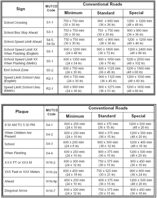
Key changes to Table 7B-1 include adding the
following signs: School Speed Limit Ahead, School Speed Limit XX When Flashing
(English), School Speed Limit XX When Flashing (Metric), School Speed Limit
(School Use) (Metric); changing sizes of the following signs: End School Zone
and Speed Limit (School Use); changing sizes for the following plaques: When
Children are Present, Ahead, Diagonal Arrow.
6. Page 7B-3, Section 7B.05, Installation of Signs. Under Support, change: “Section 2A.21” to: “Section 2A.16”.
7. Page 7B-3, Section 7B.06, Lettering. Under Support, change: “The ‘Standard Alphabets for Highway Signs and Pavement Markings’ contains…” to: “The Federal Highway Administration’s ‘Standard Alphabets for Highway Signs and Pavement Markings’ (see Section 1A.11) contains…”
8. Page 7B-3, Section 7B.07, Sign Color for School Warning Signs. Under Option D, change: “School Speed Limit sign (S5-1)” to: “The SCHOOL portion of the School Speed Limit sign (S5-1)”.
9. Page 7B-4, Section 7B.08, School Advance Warning Sign (S1-1). Under Standard, change: “The School Advance Warning (S1-1) sign shall be used in advance of any installation of the School Crossing sign.” to: “The School Advance Warning (S1-1) sign (see Figure 7B-1) shall be used in advance of any installation of the School Crossing sign (see Figure 7B-2), or in advance of the first installation of the School Speed Limit sign assembly (see Figure 7B-3)”; change: “…school grounds or school crossings (see Figure 7B-1).” to: “…school grounds or school crossings (see Figure 7B-2)”; remove: “The School Advance Warning Sign shall be used in advance of the first installation of the School Speed Limit sign assembly.”
10. Page 7B-4, Section 7B.09, School Crosswalk Warning Assembly (S1-1 with Diagonal Arrow). Under Standard, change: “…the School Crosswalk Warning assembly shall be installed…” to: “the School Crosswalk Warning assembly (see Figure7B-1) shall be installed…”
11.
Page 7B-5.
Add a figure number and title to this page of sign images: “Figure
7B-1 School Area Signs”; in the illustration on the upper left side of the
page, change: “W16-2” to: “W16-2a”, change: “W16-2a” to: “W16-2”, and label the
two plaques below “W16-2a” and “W16-2” respectively; remove the combination
S4-3/S2-5a sign and replace with two S4-5 and two S4-5a signs; replace the combination
R2-6P/S4-3/R2-1/S4-1 sign with a combination S4-3/R2-1(metric)/S4-1; add a
S5-1(metric) sign.
12.
Page 7B-5. After this page add a new page with a
figure numbered and titled “Figure 7B-2. Example of Signing for School
Crosswalk Warning Assembly”.
13.
Page 7B-6, Figure 7B-1. Typical Signing for School Area Traffic Control. Change the figure number and title to: “Figure
7B-3. Example of Signing for School Area
Traffic Control with School Speed Limits”; revise the metric School
Speed Limit signs; remove the distance plaques.
14. Page 7B-7, Section 7B.09, School Crosswalk Warning Assembly (S1-1 with Diagonal Arrow). Under Guidance, change: “…(see Figure 7B-1)…” to: “…(see Figure7B-2)…”; after the Guidance paragraph, insert the following:
Option:
The In-Street Pedestrian Crossing (R1-6 or R1-6a) sign (see Section 2B.53) may be used at unsignalized midblock school crossings. When used at a school crossing, a SCHOOL (S4-3) plaque may be mounted above the sign.
15. Page 7B-7, Section 7B.10, SCHOOL BUS STOP AHEAD Sign (S3-1). Under Guidance, change: “…sign should be installed…” to: “…sign (see Figure 7B-1) should be installed…”
16. Page 7B-7, Section 7B.11, School Speed Limit Assembly (S4-1, S4-2, S4-3, S4-4, S5-1). Under Standard, change: “A School Speed Limit assembly or a School Speed Limit (S5-1) sign shall be used…” to: “A School Speed Limit assembly (see Figure 7B-1) or a School Speed Limit (S5-1) sign (see Figure 7B-1) shall be used…”
17.
Page 7B-8, Section 7B.11, School Speed Limit Assembly
(S4-1, S4-2, S4-3, S4-4, S5-1).
Under Standard, in the second paragraph, add: “(see Figure 7B-1)” to the
end of the sentence. Under Option,
below the first paragraph insert the following text:
Changeable message signs should subscribe to principles established in Section 2A.07 and other Sections of this Manual and, to the extent practical, with the design (that is, color, letter size and shape, and borders) and applications prescribed in this Manual, except that the reverse colors for the letters and the background are considered acceptable (see Section 6F.52). Fluorescent yellow-green pixels may be used when school-related messages are shown on a changeable message sign.
Then,
below the second paragraph of the Option, insert following text: “Changeable
message signs that display the speed of approaching drivers (see Section 2B.11)
may be used in a school speed limit zone.”; in the third paragraph, at the end
of the second sentence add: (see Figure 7B-1)”; and after the last paragraph
insert the following paragraph: “A FINES HIGHER (R2-6) sign (see Section 2B.15)
may be used to advise road users when increased fines are imposed for traffic
violations in school zones.”
18. Page 7B-8, Section 7B.12, School Reduced Speed Ahead Assembly. Change Section title to: “Section 7B.12 School Reduced Speed Ahead Sign (S4-5, S4-5a)”; under Option, change: “The School Reduced Speed Ahead assembly may …” to: “The School Reduced Speed Zone Ahead (S4-5, S4-5a) sign (see Figure 7B-1) may …” change: “…used to inform the road…” to: “…used to inform road…”
19. Page 7B-9, Section 7B.12, School Reduced Speed Ahead Assembly. Under Standard, delete first paragraph; change: “If used, the School Reduced Speed Ahead assembly shall be followed…” to: “If used, the School Reduced Speed Zone Ahead sign shall be followed”; insert at the bottom the following text: “The speed limit displayed on the School Reduced Speed Zone Ahead sign shall be identical to the speed limit displayed on the subsequent School Speed Limit sign or School Speed Limit assembly.”
20. Page 7B-9, Section 7B.13, END SCHOOL ZONE Sign (S5-2). Under Standard, change: “…an END SCHOOL ZONE (S5-2) sign.” to: “…an END SCHOOL ZONE (S5-2) sign (see Figure 7B-1).”
21. Page 7C-1, Section 7C.03, Crosswalk Markings. After the Section title, insert:
Support:
Crosswalk markings provide guidance for pedestrians who are crossing roadways by defining and delineating paths on approaches to and within signalized intersections, and on approaches to other intersections where traffic stops.
Crosswalk markings also serve to alert road users of a pedestrian crossing point across roadways not controlled by traffic signals or STOP signs.
At nonintersection locations, crosswalk markings legally establish the crosswalk.
After
the third paragraph of the Guidance, add: “Crosswalk lines should not be used
indiscriminately. An engineering study
should be performed before they are installed at locations away from traffic
control signals or STOP signs.
22. Page 7C-2, Section 7C.03, Crosswalk Markings. Under Guidance, change: “…wide and spaced 300 to 600 mm (12 to 24 in) apart.” to: “…wide and spaced 300 to 1500 mm (12 to 60 in) apart.”
23. Page 7C-2, Section 7C.04, Stop Line Markings. Change the section title to: “Section 7C.04 Stop and Yield Lines”; under Standard, change: “Stop lines shall consist…” to: “If used, stop lines shall consist”; add the following paragraph: “If used, yield lines (see Figure 3B-14) shall consist of a row of isosceles triangles pointing toward approaching vehicles extending across approach lanes to indicate the point at which the yield is intended or required to be made”; under Guidance, in the first paragraph, change:
Stop lines should be 300 to 600 mm (12 to 24 in) wide. Stop lines should be used to indicate the point behind which vehicles are required to stop, in compliance with a STOP sign or traffic signal. Stop lines, if used, should be placed 1.2 m (4 ft) in advance of the nearest crosswalk line, except at roundabouts as provided for in Section 3B.24. In the absence of a marked crosswalk, the stop line should be placed at the desired stopping point, but should be placed no more than 9 m (30 ft) nor less than 1.2 m (4 ft) from the nearest edge of the intersecting traveled way.
to:
Stop lines should be 300 to 600 mm (12 to 24 in) wide. Stop lines should be used to indicate the point behind which vehicles are required to stop, in compliance with a STOP (R1-1) sign (see Figure 2B-1), traffic control signal, or some other traffic control device.
Under Guidance, in the second paragraph change: “Stop lines should be placed to ensure sufficient sight distance for all approaches to an intersection. Stop lines at mid-block signalized locations should be placed at least 12 m (40 ft) in advance of the nearest signal indication (see Section 4D.15).” to: “The individual triangles comprising the yield line should have a base of 0.3 to 0.6 m (12 to 24 in) wide and a height equal to 1.5 times the base. The space between the triangles should be 75 to 300 mm (3 to 12 in).” Under the last paragraph of the first Guidance add the following text:
Option:
Yield lines may be used to indicate the point behind which vehicles are required to yield in compliance with a YIELD (R1-2) sign (see Figure 2B-1) or a Yield Here to Pedestrians (R1-5 or R1-5a) sign (see Figure 2B-22).
Guidance:
If used, stop and yield lines should be placed a minimum of 1.2 m (4 ft) in advance of and parallel to the nearest crosswalk line at controlled intersections, except for yield lines at roundabouts as provided for in Section 3B.24 and at midblock crosswalks. In the absence of a marked crosswalk, the stop line or yield line should be placed at the desired stopping or yielding point, but should be placed no more than 9 m (30 ft) nor less than 1.2 m (4 ft) from the nearest edge of the intersecting traveled way. Stop lines should be placed to allow sufficient sight distance for all approaches to an intersection.
If used at an unsignalized midblock crosswalk, yield lines should be placed adjacent to the Yield Here to Pedestrians sign located 6.1 to 15 m (20 to 50 ft) in advance of the nearest crosswalk line, and parking should be prohibited in the area between the yield line and the crosswalk (see Figure 3B-15).
Stop lines at midblock signalized locations should be placed at least 12 m (40 ft) in advance of the nearest signal indication (see Section 4D.15).
Support:
Drivers who yield too close to crosswalks on multilane approaches place pedestrians at risk by blocking other drivers’ views of pedestrians.
24. Page 7C-3, Section 7C.05, Curb Markings for Parking Regulations. Under Option, change: “Local authorities…” to: “Local highway agencies...”
25. Page 7C-3, Section 7C.06, Pavement Word and Symbol
Markings. Under Support after the
first sentence, add: “Symbol messages are preferable
to word messages.”
26. Page 7C-3 and 7C-4, Section 7C.06, Pavement Word and Symbol Markings. Under Guidance, in the first paragraph, in the first
sentence, change: “Large letters and numerals…” to: “Letters and numerals…”; and in the second
sentence change: “…in accordance with the ‘Standard Alphabets for highway Signs
and Pavement Markings.’” to: “…in accordance with the Federal Highway
Administration’s ‘Standard Alphabets for highway Signs and Pavement Markings.’
(see Section 1A.11)”; After the fourth paragraph, insert the
following new paragraph: “The number of different word and symbol markings
used should be minimized to provide effective guidance and avoid
misunderstanding.”; and in the existing fifth paragraph of the Guidance,
change: “Except as noted
in the Option,” to: “Except as noted in the Option
below,…”
27.
Page 7E-2, Section 7E.04, Uniform of Adult guards
and Student Patrols. Under Guidance, change the second paragraph to a
Standard; change: “Adult guards and student patrols should wear high-visibility
retroreflective material or clothing similar to that set forth in Section
6E.02” to: “Adult guards shall wear high-visibility retroreflective clothing
labeled as ANSI 107-1999 standard performance for Class 2 as described in
Section 6E.02”; add a new paragraph: “Student patrols shall wear
high-visibility retroreflective clothing labeled as ANSI 107-1999 standard
performance for Class 1 as described in Section 6E.02; the last paragraph of
the section remains a Guidance.
28. Page 7E-2, Section 7E.05 Operating Procedures for Adult Guards. After the Standard, add:
Option:
The STOP paddle may be modified to improve conspicuity by incorporating white flashing lights on both sides of the paddle. The white flashing lights may be arranged in any of the following patterns:
A. Two white lights centered vertically above and below the STOP legend;
B. Two white lights centered horizontally on each side of the STOP legend;
C. One white light centered below the STOP legend; or
D. A series of eight or more small white lights no larger than 6 mm (1/4 in) in diameter along the outer edge of the paddle, arranged in an octagonal pattern at the eight corners of the STOP paddle. More than eight lights may be used only if the arrangement of the lights is such that it clearly conveys the octagonal shape of the STOP paddle.”
Add a second Standard and insert following text: “If flashing lights are used on the STOP paddle, the flash rate shall be at least 50, but not more than 60, flash periods per minute.”
Part 8
1. Cover of Part 8. Change: “Incorporating: Errata No. 1 dated June 14, 2001” to: “Incorporating: Proposed Revision No. 2, Errata No. 1 dated June 14, 2001.”
2. Pages 8A-1 through 8A-3, Section 8A.01, Introduction. Under Support, in the first paragraph, change: “Traffic control for highway-rail grade crossings include all signs, signals, markings, and other warning devices. It also includes their supports…” to: “Traffic control for highway-rail grade crossings includes all signs, signals, markings, other warning devices, and their supports...”; under Standard, change:
The traffic control devices, systems, and practices described herein shall be used at all highway-rail grade crossings open to public travel, consistent with Federal, State, and local laws and regulations.
To ensure an understanding of common terminology between highway and railroad signaling issues, the following definitions shall be used:
1. Advance Preemption and Advance Preemption Time—notification of an approaching train is forwarded to the highway traffic signal controller unit or assembly by railroad equipment for a period of time prior to activating the railroad active warning devices. This period of time is the difference in the maximum preemption time required for highway traffic signal operation and the minimum warning time needed for railroad operations and is called the advance preemption time.
2. Cantilevered Signal Structure—a structure that is rigidly attached to a vertical pole and is used to provide overhead support of signal units.
3. Clear Storage Distance—the distance available for vehicle storage measured between 1.8 m (6 ft) from the rail nearest the intersection to the intersection stop line or the normal stopping point on the highway. At skewed highway- rail grade crossings and intersections, the 1.8 m (6 ft) distance shall be measured perpendicular to the nearest rail either along the centerline or edge line of the highway, as appropriate, to obtain the shorter clear distance.
4. Design Vehicle—the longest vehicle permitted by statute of the road authority (State or other) on that roadway.
5. Dynamic Envelope Delineation—the dynamic envelope is the clearance required for the train and its cargo overhang due to any combination of loading, lateral motion, or suspension failure (see Figure 8A-1).
6. Interconnection—the electrical connection between the railroad active warning system and the traffic signal controller assembly for the purpose of preemption.
7. Maximum Preemption Time—the maximum amount of time needed following initiation of the preemption sequence for the highway traffic signals to complete the timing of the right-of-way transfer time, queue clearance time, and separation time.
8. Minimum Track Clearance Distance—for standard two-quadrant railroad warning devices, the minimum track clearance distance is the length along a highway at one or more railroad tracks, measured either from the highway stop line, warning device, or 3.7 m (12 ft) perpendicular to the track centerline, to 1.8 m (6 ft) beyond the track(s) measured perpendicular to the far rail, along the centerline or edge line of the highway, as appropriate, to obtain the longer distance.
9. Minimum Warning Time—Through Train Movements—the least amount of time active warning devices shall operate prior to the arrival of a train at a highway-rail grade crossing.
10. Monitored Interconnected Operation—an interconnected operation that has the capability to be monitored by the railroad and/or highway authority at a location away from the highway-rail grade crossing.
11. Preemption—the transfer of normal operation of traffic signals to a special control mode.
12. Presignal—supplemental highway traffic signal faces operated as part of the highway intersection traffic signals, located in a position that controls traffic approaching the railroad crossing and intersection.
13. Queue Clearance Time—the time required for the design vehicle stopped within the minimum track clearance distance to start up and move through the minimum track clearance distance. If presignals are present, this time shall be long enough to allow the vehicle to move through the intersection, or to clear the tracks if there is sufficient clear storage distance.
14. Right-of-Way Transfer Time—the maximum amount of time needed for the worst case condition, prior to display of the track clearance green interval. This includes any railroad or traffic signal control equipment time to react to a preemption call, and any traffic signal green, pedestrian walk and clearance, yellow change, and red clearance intervals for conflicting traffic.
15. Separation Time—the component of maximum preemption time during which the minimum track clearance distance is clear of vehicular traffic prior to the arrival of the train.
16. Simultaneous Preemption—notification of an approaching train is forwarded to the highway traffic signal controller unit or assembly and railroad active warning devices at the same time.
to:
The traffic control devices, systems, and practices described herein shall be used at all highway-rail grade crossings open to public travel, consistent with Federal, State, and local laws and regulations.
To ensure an understanding of common terminology between highway and railroad signaling issues, the following definitions shall be used:
1. Advance Preemption—the notification of an approaching train that is forwarded to the highway traffic signal controller unit or assembly by the railroad equipment for a period of time prior to activating the railroad active warning devices.
2. Advance Preemption Time—the period of time that is the difference between the maximum preemption time required for highway traffic signal operation and the minimum warning time needed for railroad operations.
3. Cantilevered Signal Structure—a structure that is rigidly attached to a vertical pole and is used to provide overhead support of signal units.
4. Clear Storage Distance—the distance available for vehicle storage measured between 1.8 m (6 ft) from the rail nearest the intersection to the intersection stop line or the normal stopping point on the highway. At skewed highway- rail grade crossings and intersections, the 1.8 m (6 ft) distance shall be measured perpendicular to the nearest rail either along the centerline or edge line of the highway, as appropriate, to obtain the shorter distance. Where exit lane gates are used, the distance available for vehicle storage is measured from the point where the rear of the vehicle would be clear of the exit lane gate arm. In cases where the exit lane gate arm is parallel to the track(s) and is not perpendicular to the highway, the distance is measured either along the centerline or edge line of the highway, as appropriate, to obtain the shorter distance.
5. Design Vehicle—the longest vehicle permitted by statute of the road authority (State or other) on that roadway.
6. Dynamic Envelope—the clearance required for the train and its cargo overhang due to any combination of loading, lateral motion, or suspension failure (see Figure 8A-1).
7. Dynamic Exit Lane Gate Operating Mode—a mode of operation where the exit lane gate operation is based on the presence of vehicles within the minimum track clearance distance.
8. Exit Lane Gate Operating Mode—for Four-Quadrant Gate systems, the mode of control used to govern the operation of the exit lane gate arms.
9. Exit Lane Gate Clearance Time—for Four-Quadrant Gate warning systems, the exit gate clearance time is the amount of time provided to delay the descent of the exit lane gate arm(s) after the approach lane gate arm(s) begin to descend.
10. Flashing-Light Signals—a special type of highway traffic signal used at highway-rail grade crossings to inform drivers of the approach or presence of a train.
11. Interconnection—the electrical connection between the railroad active warning system and the traffic signal controller assembly for the purpose of preemption.
12. Maximum Preemption Time—the maximum amount of time needed following initiation of the preemption sequence for the highway traffic signals to complete the timing of the right-of-way transfer time, queue clearance time, and separation time.
13. Minimum Track Clearance Distance—for standard two-quadrant railroad warning devices, the minimum track clearance distance is the length along a highway at one or more railroad tracks, measured either from the highway stop line, warning device, or 3.7 m (12 ft) perpendicular to the track centerline, to 1.8 m (6 ft) beyond the track(s) measured perpendicular to the far rail, along the centerline or edge line of the highway, as appropriate, to obtain the longer distance. For Four-Quadrant Gate systems, the minimum track clearance distance is the length along a highway at one or more railroad tracks, measured either from the highway stop line or entrance warning device, to the point where the rear of the vehicle would be clear of the exit lane gate arm. In cases where the exit lane gate arm is parallel to the track(s) and is not perpendicular to the highway, the distance is measured either along the centerline or edge of the highway, as appropriate, to obtain the longer distance.
14. Minimum Warning Time—Through Train Movements—the least amount of time active warning devices shall operate prior to the arrival of a train at a highway-rail grade crossing.
15. Monitored Interconnected Operation—an interconnected operation that has the capability to be monitored by the railroad company and/or highway authority at a location away from the highway-rail grade crossing.
16. Preemption—the transfer of normal operation of traffic signals to a special control mode.
17. Presignal—supplemental highway traffic signal faces operated as part of the highway intersection traffic signals, located in a position that controls traffic approaching the highway-rail grade crossing and intersection.
18. Queue Clearance Time—the time required for the design vehicle of maximum length stopped just inside the minimum track clearance distance to start up and move through and clear the entire minimum track clearance distance. If presignals are present, this time shall be long enough to allow the vehicle to move through the intersection, or to clear the tracks if there is sufficient clear storage distance. If a Four-Quadrant Gate system is present, this time shall be long enough to permit the exit lane gate arm to lower after the design vehicle is clear of the minimum track clearance distance.
19. Right-of-Way Transfer Time—the maximum amount of time needed for the worst case condition, prior to display of the track clearance green interval. This includes any railroad or traffic signal control equipment time to react to a preemption call, and any traffic signal green, pedestrian walk and clearance, yellow change, and red clearance intervals for conflicting traffic.
20. Separation Time—the component of maximum preemption time during which the minimum track clearance distance is clear of vehicular traffic prior to the arrival of the train.
21. Simultaneous Preemption—notification of an approaching train is forwarded to the highway traffic signal controller unit or assembly and railroad active warning devices at the same time.
22. Timed Exit Gate Operating Mode—a mode of operation where the exit lane gate descent is based on a predetermined time interval.
23. Vehicle Intrusion Detection Devices—a detector or detectors used as a part of a system incorporating processing logic to detect the presence of vehicles within the minimum track clearance distance and to control the operation of the exit lane gates.
24. Wayside Equipment—the signals, switches, and/or control devices for railroad operations housed within one or more enclosures located along the railroad right-of-way and/or on railroad property.
3. Page 8A-2, Figure 8A-1. Train Dynamic Envelope Delineation. From the Figure title, delete “Delineation.”
4. Page 8A-4, Section 8A.02, Use of Standard Devices, Systems, and Practices. Under Guidance, change: “The appropriate traffic control system should be determined by an engineering study involving both the highway agency and the railroad company.” to: “The appropriate traffic control system to be used at a highway-rail grade crossing should be determined by an engineering study involving both the highway agency and the railroad company.”; under second Support, change: “More detail on HRI is available from USDOT’s Federal Railroad Administration, 400 Seventh Street SW, Washington, DC 20590,” to: “More detail on Highway-Rail Intersection components is available from USDOT’s Federal Railroad Administration, 1120 Vermont Ave., NW, Washington, DC 20590, or www.fra.dot.gov.”; under Standard, in the first paragraph change: “…with the design and application of the standards contained herein.” to: “…with the design and application of the Standards contained herein.”; in the second paragraph change: “Before a new or modified highway-rail grade crossing is installed, approval shall be obtained…” to: “Before any new highway-rail grade crossing traffic control system is installed or before modifications are made to an existing system, approval shall be obtained…”; insert a new second Guidance:
To stimulate effective responses from drivers, pedestrians, and bicyclists, these devices, systems, and practices should use the five basic considerations employed generally for traffic control devices and described fully in Section 1A.02: design, placement, operation, maintenance, and uniformity.
Under the second Support, change: “…traffic control systems that are not set forth herein are contained…” to: “…traffic control systems that are not set forth in Part 8 are contained…”
5. Page 8A-5, Section 8A.03, Uniform Provisions. Under Guidance, change: “Such signs or signals should be installed at least 0.6 m (2 ft) from the face of each curb to the nearest…” to: “Such signs or signals should be installed with a clearance of at least 0.6 m (2 ft) from the face of the curb to the nearest…”
6. Page 8A-5, Section 8A.04, Highway-Rail Grade Crossing Elimination. Before the Standard, insert a new first Guidance: “Because highway-rail grade crossings are a potential source of congestion, agencies should conduct engineering studies to determine the cost and benefits of eliminating these crossings.”; and at the end of the Section, insert a new Option: “The TRACKS OUT OF SERVICE (R8-9) sign (see Figure 8B-4) may be temporarily installed until the tracks are removed or paved over.”
7. Page 8A-5, Section 8A.05, Temporary Traffic Control Zones. Before the Standard, insert a new Support:
Temporary traffic control planning provides for continuity of operations (such as movement of traffic, pedestrians and bicycles, transit operations, and access to property/utilities) when the normal function of a roadway at a highway-rail grade crossing is suspended because of temporary traffic control operations.
8. Page 8A-6, Section 8A.0-5, Temporary Traffic Control Zones. Under Guidance, in the second paragraph, change: “Inconvenience, delay, and crash potential to affected traffic should be minimized.” to: “Temporary traffic control operations should minimize the inconvenience, delay, and crash potential to affected traffic.”; change: “…emergency services, businesses, railroad companies, and road users before free movement of vehicles or trains is infringed upon or blocked.” to: “…emergency services, businesses, railroad companies, and road users before the free movement of vehicles or trains is infringed upon or blocked.”; and in the third paragraph change: “Temporary traffic control zone activities should not extensively prolong the closing…” to: “Temporary traffic control zone activities should not be permitted to extensively prolong the closing…”
9. Page 8B-1, Section 8B.02, Highway-Rail Grade Crossing (Crossbuck) Signs (R15-1, R15-2). Change the Section title to: “Section 8B.02 Highway-Rail Grade Crossing (Crossbuck) Signs (R15-1, R15-2, R15-9)”; under Option, following the first paragraph, insert a new paragraph: “A Crossbuck Shield (R15-9) sign (see Figure 8B-2) may be mounted below the Crossbuck sign or Number of Tracks sign as shown in Figure 8B-1.”; under the second Standard insert before the existing first paragraph:
If the Crossbuck Shield sign is used, it shall consist of red retroreflective stripes on a white retroreflective background as shown in Figure 8B-2. The red stripes shall have a width of 100 mm (4 in). If used, the Crossbuck Shield sign shall be mounted at a height of 750 mm (30 in) measured from the bottom of the sign to the roadway level.
10. Page 8B-2, Figure 8B-1. Highway-Rail Grad Crossing (Crossbuck) Signs. Add a new dimension of “0.3 m (1 ft) max.” from the roadway level to the bottom of the white retroreflective strip on the post; add a new second drawing of a Crossbuck assembly showing on the post, in addition to the Crossbuck and 3 TRACKS signs, a Crossbuck Shield Sign (R15-9) with a vertical dimension of “950 mm (38 in)” mounted below the 3 TRACKS sign with the bottom of the Crossbuck Shield sign at 0.75 m (2.5 ft) above the roadway level.
11. Page 8B-2. Immediately after this page insert a new page with a new figure numbered and titled “Figure 8B-2. Crossbuck Shield Sign (R15-9)” and illustrating a front view, a (front) top view, and a back view of the R13-5 Crossbuck Shield sign.
12. Pages 8B-1 and 8B-3, Section 8B.02, Highway-Rail Grade Crossing (Crossbuck) Signs (R15-1, R15-2). In the Standard, in the last paragraph change: “…from the Crossbuck sign or Number of Tracks sign to near ground level.” to: “…from the Crossbuck sign or Number of Tracks sign to within 0.3 m (1 ft) of the ground level, except on the side of those supports where a Crossbuck Shield sign or flashing lights have been installed.”; under Guidance, in the second paragraph, change: “The lateral clearance for the nearest edge of the Crossbuck sign…” to: “The minimum lateral clearance for the nearest edge of the Crossbuck sign”; change: “…from the edge of the traveled way in rural areas, and 0.6 m (2 ft)…” to: “…from the edge of the traveled way in rural areas (whichever is greater), and 0.6 m (2 ft)…”
13. Pages 8B-3 and 8B-4, Section 8B.03, Highway-Rail Grade Crossing Advance Warning Signs (W10 Series). Change the first Standard from:
A Highway-Rail Grade Crossing Advance Warning (W10-1) sign shall be used on each highway in advance of every highway-rail grade crossing except in the following circumstances:
A. If the distance between the
railroad tracks and the parallel highway, from the edge of the track to the
edge of the highway, is less than 30 m (100 ft), the W10-2, W10-3, or W10-4
signs shall be used on the parallel highway to warn road users making a turn
that they will encounter a highway-rail grade crossing soon after making the
turn;
B. On low-volume, low-speed highways crossing minor spurs or other tracks that are infrequently used and are flagged by train crews;
C. In business districts where active highway-rail grade crossing traffic control devices are in use; and
D. Where physical conditions do not permit even a partially effective display of the sign.
Placement of the Highway-Rail Grade Crossing Advance Warning sign shall be in accordance with Table 2C-4 in Chapter 2C.
to:
A Highway-Rail Grade Crossing Advance Warning (W10-1) sign (see Figure 8B-3) shall be used on each highway in advance of every highway-rail grade crossing except in the following circumstances:
A. On an approach to a highway-rail grade crossing from a T-intersection with a parallel highway, if the distance from the edge of the track to the edge of the parallel roadway is less than 30 m (100 ft), and W10-3 signs are used on both approaches of the parallel highway; or
B. On low-volume, low-speed highways crossing minor spurs or other tracks that are infrequently used and are flagged by train crews; or
C. In business districts where active highway-rail grade crossing traffic control devices are in use; or
D. Where physical conditions do not permit even a partially effective display of the sign.
Placement of the Highway-Rail Grade Crossing Advance Warning sign shall be in accordance with Chapter 2A and Table 2C-4.
14. Page 8B-4, Section 8B.03, Highway-Rail Grade Crossing Advance Warning Signs (W10 Series). Under the second Standard, insert the following as a new first paragraph:
If the distance between the railroad tracks and a parallel highway, from the edge of the tracks to the edge of the parallel roadway, is less than 30 m (100 ft), W10-2, W10-3, or W10-4 signs (see Figure 8B-3) shall be installed on each approach of the parallel highway to warn road users making a turn that they will encounter a highway-rail grade crossing soon after making a turn, and a W10-1 sign for the approach to the tracks shall not be required to be between the tracks and the parallel highway.
In the existing first (new second) paragraph change: “…sign placement shall be in accordance with Table 2C-4 in Chapter 2C (using the speed of the turning maneuver), …” to: “…sign placement shall be in accordance with Table 2C-4 (using the speed of the turning maneuver), …”; and in the Guidance change: “…from the edge of the roadway…” to: “…to the edge of the parallel roadway…”
15. Page 8B-4. For the sign images at the top of the page, add a figure number and title: “Figure 8B-3. Advance Warning Signs”.
16. Page 8B-5, Section 8B.04, EXEMPT Highway-Rail Grade Crossing Signs (R15-3, W10-1a). Under Option, change:
When authorized by law or regulation, a supplemental sign (R15-3) with a white background bearing the word EXEMPT may be used below the Crossbuck sign or Number of Tracks sign, if present, at the highway-rail grade crossing, and a supplemental sign (W10-1a) with a yellow background bearing the word EXEMPT may be used below the Highway-Rail Advance Warning sign.
to:
When authorized by law or regulation, a supplemental EXEMPT (R15-3) sign (see Figure 8B-4) with a white background bearing the word EXEMPT may be used below the Crossbuck sign or Number of Tracks sign, if present, at the highway-rail grade crossing, and a supplemental EXEMPT (W10-1a) sign (see Figure 8B-4) with a yellow background bearing the word EXEMPT may be used below the Highway-Rail Advance Warning (W10-1) sign.
17. Page 8B-5. For the sign images at the bottom of the page, add a figure number and title:: “Figure 8D-4. Regulatory Signs.”; change the TRACKS OUT OF SERVICE sign from a square shape with 3 lines of legend to a rectangular shape with 4 lines of legend; add illustrations of R3-1a, R3-2a, R8-10, R10-6, R15-3/W10-1a, and R15-8 signs; and rearrange the layout of signs within the figure.
18. Page 8B-6, Section 8B.05, Turn Restrictions During Preemption. Under Option, at the end of the paragraph, insert the following text: “The R3-1a and R3-2a signs shown in Figure 8B-4 may be used for this purpose.”
19. Page 8B-6, Section 8B.06, DO NOT STOP ON TRACKS Sign (R8-8). Under the first paragraph of Guidance, change: “…a DO NOT STOP ON TRACKS (R8-8) sign should be used.” to: “…a DO NOT STOP ON TRACKS (R8-8) sign (see Figure 8B-4) should be used.”; in the second paragraph of Guidance change: “…on the right side of the highway on the near or far side…” to: “…on the right side of the highway on either the near or far side…”; and under Option, in the second paragraph change: “…to further improve visibility.” to: “…to further improve visibility of the sign.”
20. Page 8B-7, Section 8B.07, STOP or YIELD Signs at Highway-Rail Grade Crossings. Change the Section title to: “Section 8B.07 STOP (R1-1) or YIELD (R1-2) Signs at Highway-Rail Grade Crossings”; Under the first Option, change: “…STOP (R1-1) or YIELD (R1-2) signs may be used…” to: “…STOP (R1-1) or YIELD (R1-2) signs (see Figure 2B-1) may be used…”; under the Standard, in the first sentence change: “For all highway-rail grade crossings where STOP or YIELD signs are installed, the placement shall conform to the requirements of Chapter 2B.” to: “For all highway-rail grade crossings where STOP or YIELD signs are installed, the placement shall conform to the requirements of Sections 2B.06 and 2B.10.” and in the second sentence change: “…Advance Warning signs shall also be installed…” to: “…Advance Warning signs (see Figure 2C-5) shall also be installed…”
21. Page 8B-7, Section 8B.08, TRACKS OUT OF SERVICE Sign (R8-9). Under Option, change:
The TRACKS OUT OF SERVICE (R8-9) sign may be used at a highway-rail grade crossing instead of Crossbuck signs (R15-1, R15-2) when railroad tracks have been temporarily or permanently abandoned, but only until such time that the tracks are removed or paved over.
to:
The TRACKS OUT OF SERVICE (R8-9) sign (see Figure 8B-4) may be used at a highway-rail grade crossing instead of a Crossbuck (R15-1) sign and a Number of Tracks (R15-2) sign (see Figure 8B-1) when railroad tracks have been temporarily or permanently abandoned, but only until such time that the tracks are removed or paved over.
22. Page 8B-8. Immediately before the existing Section 8B.09, insert a new Section numbered and titled: “Section 8B.09 STOP HERE WHEN FLASHING Sign (R8-10)”. The new Section reads as follows:
Option:
The STOP HERE WHEN FLASHING (R10-8) sign (See Figure 8B-4) may be used at a highway-rail grade crossing to inform drivers of the location of the stop line or the point at which to stop when the flashing-light signals (see Section 8D.02) are activated.
Then, immediately after the newly-inserted new Section 8B.09, insert an additional new Section numbered and titled: “Section 8B.10 STOP HERE ON RED Sign (R10-6)”. The new Section reads as follows:
Support:
The STOP HERE ON RED (R10-6) sign (see Figure 8B-4) defines and facilitates observance of stop lines at traffic signals or traffic gates.
Option:
A STOP HERE ON RED sign may be used at locations where vehicles frequently violate the stop line or where it is not obvious to road users where to stop.
Guidance:
If possible, stop lines should be placed at a point where the vehicle driver has adequate sight distance along the track.
23. Page 8B-8, Section 8B.09, Emergency Notification Sign (I-13 or I-13a). Change the Section number to: “Section 8B.11”; under Guidance, change: “An Emergency Notification sign (I-13 or I-13a) should be posted at…” to: “An Emergency Notification (I-13 or I-13a) sign (see Figure 8B-5) should be installed at…”; under Support, change: “Typical sign messages are shown in the following examples:” to: “Typical sign messages are shown in Figure 8B-5.”
24.
Page 8B-8. To
the sign images at the bottom of the page, add a figure number and title: “Figure 8B-5. Emergency Notification Signs”.
25. Page 8B-9, Section 8B.10, TRAINS MAY EXCEED 130 km/h (80 MPH) Signs (W10-8, W10-8a). Change the Section number and title to: “Section 8B.12 TRAINS MAY EXCEED 130 km/h (80 MPH) Sign (W10-8)”; under Guidance, in the first paragraph change: “…a TRAINS MAY EXCEED 130 km/h (80 MPH) (W10-8 or W10-8a) sign should be…” to: “…a TRAINS MAY EXCEED 130 km/h (80 MPH) (W10-8) sign (see Figure 8B-6) should be…”; in the second paragraph change: “…signs should be posted between…” to: “…signs should be installed between”; change: “…Advance Warning (W10-1) sign…” to: “…Highway-Rail Grade Crossing Advance Warning (W10-1) sign (see Figure 8B-3)…”
26. Page 8B-9, Section 8B.11, NO TRAIN HORN Sign (W10-9). Change the Section number to: “Section 8B.13”; under Standard, change: “A NO TRAIN HORN (W10-9) sign shall be installed at each highway-rail grade…” to: “A NO TRAIN HORN (W10-9) sign (see Figure 8B-6) shall be installed at each highway-rail grade”; change: “…Advance Warning (W10-1) sign.” to: “…Highway-Rail Grade Crossing Advance Warning (W10-1) sign (see Figure 8B-3).”
27. Page 8B-9, Section 8B.12, NO SIGNAL Sign (W10-10). Change Section number and title to: “Section 8B.14 NO SIGNAL Sign (W10-10) or NO GATES OR LIGHTS Sign (W10-13)”; Under Option, change:
A NO SIGNAL (W10-10) sign may be installed at highway-rail grade crossings that are not equipped with automated signals.
The NO SIGNAL sign may be mounted as a supplemental plaque below the Advance Warning sign.
to:
A NO SIGNAL (W10-10) sign or a NO GATES OR LIGHTS (W10-13) sign (see Figure 8B-6) may be installed at highway-rail grade crossings that are not equipped with automated signals.
The NO SIGNAL (W10-10) sign or the NO GATES OR LIGHTS (W10-13) sign may be mounted as a supplemental plaque below the Advance Warning (W10-1) sign.
28. Page 8B-9, Section 8B.13, LOOK Sign (R15-8). Change the Section number to: “Section 8B.15”; under Option, change: “At highway-rail grade crossings that do not have active warning devices, the LOOK (R15-8) sign may be mounted…” to: “At highway-rail grade crossings, the LOOK (R15-8) sign (see Figure 8B-4) may be mounted…”
29. Page 8B-10. Add a figure number and title to this page of sign images: “Figure 8B-6. Warning Signs”; add the word “OR” between the two “TRAINS MAY EXCEED..” signs; delete the “W10-8a” designation for the metric version of the “TRAINS MAY EXCEED…” sign; delete the R15-8 “LOOK” sign from this figure; add an illustration of a W10-13 “NO GATES OR LIGHTS” sign; add an illustration of a W10-12 Skewed Crossing sign; and rearrange the signs within the page.
30. Page 8B-11, Section 8B.14, Low Ground Clearance Highway-Rail Grade Crossing Sign (W10-5). Change the Section number to: “Section 8B.16”; under the first Guidance, change: “…the Low Ground Clearance Highway-Rail Grade Crossing (W10-5) sign should be installed in advance…” to: “…the Low Ground Clearance Highway-Rail Grade Crossing (W10-5) sign (see Figure 8B-6) should be installed in advance…”; under the Standard change: “…(see Chapter 2A).” to: “…(see Section 2A.13).”
31. Pages 8B-11 and 8B-12, Section 8B.15, Storage Space Signs (W10-11a, W10-11b). Change the Section number to: “Section 8B.17”; under Guidance, change: “A Storage Space (W10-11) sign supplemented by a word message storage distance (W10-11) sign should be used where…” to: “A Storage Space (W10-11) sign supplemented by a word message storage distance (W10-11a) sign (see Figure 8B-6) should be used where…”; under Option, change: “The Storage Space sign, W10-11b, may be mounted beyond the highway-rail…” to: “A Storage Space (W10-11b) sign (see Figure 8B-6) may be mounted beyond the highway-rail…”
32. Page 8B-12. Immediately before existing Section 8B.16, insert a new Section numbered and titled: “Section 8B.18 Skewed Crossing Sign (W10-12)”. The new Section reads as follows:
Option:
The Skewed Crossing (W10-12) sign (see Figure 8B-6) may be used at a skewed highway-rail grade crossing to warn drivers that the railroad tracks are not perpendicular to the highway.
Guidance:
If used, the symbol on the Skewed Crossing sign should show the direction and approximate angle of the crossing.
Standard:
The Skewed Crossing sign shall not be used as a replacement for the required Advance Warning (W10-1) sign. If used, the Skewed Crossing sign shall supplement the W10-1 sign and shall be mounted on a separate post.
33. Page 8B-12, Section 8B-16, Pavement Markings. Change the Section number to: “Section 8B.19”; under the first Standard, change: “All highway-rail grade crossing markings…” to: “All highway-rail grade crossing pavement markings...”; in the second paragraph change: “…and certain transverse lines as shown in Figures 8B-2 and 8B-3.” to: “…and certain transverse lines as shown in Figures 8B-7 and 8B-8.”
34. Page 8B-13, Figure 8B-2. Typical Placement of Warning Signs and Pavement Markings at Highway-Rail Grade Crossings. In Figure title, change: “Figure 8B-2” to: “Figure 8B-7” and change: “Typical” to: “Example of”; in the dimensions shown for the pavement marking symbol, change the figure reference from “(See Figure 8B-3)” to “(See Figure 8B-8)”.
35. Page 8B-14, Figure 8B-3. Typical Highway-Rail Grade Crossing Pavement Markings. In Figure title, change: “Figure 8B-3” to: “Figure 8B-8” and change “Typical” to “Examples of”; in the “Note” change the figure reference from “Figure 8B-2” to “Figure 8B-7”.
36. Page 8B-15, Section 8B.17, Stop Lines. Change the Section number to: “ Section 8B.20”.
37. Page 8B-15, Section 8B.18, Dynamic Envelope Delineation. Change the Section number and title to: “Section 8B.21 Dynamic Envelope Markings”; under Option, insert as a new second paragraph: “Dynamic envelope markings may be installed at all highway-rail grade crossings, unless a Four-Quadrant Gate system (see Section 8D.05) is used.”; under Guidance, change: “The pavement markings should extend across the roadway as shown in Figure 8B-4.” to: “The pavement markings should extend across the roadway as shown in Figure 8B-9.”
38. Page 8B-16, Figure 8B-4. Typical Train Dynamic Envelope Delineation Pavement Markings. Change the figure number and title to: “Figure 8B-9 Example of Train Dynamic Envelope Pavement Markings”; in the “Note” to the Figure, in line two, change “…show the delineation markings,..” to “…show the dynamic envelope markings,…”
39. Page 8C-1, Section 8C.01, Illumination at Highway-Rail Grade Crossings. Change Option to Guidance and change: “…illumination at and adjacent to the highway-rail grade crossing may be installed.” to: “…illumination should be installed at and adjacent to the highway-rail grade crossing.”; under Support, change: “Practice for Roadway Lighting RP8” to: “Practice for Roadway Lighting RP-8”.
40.
Pages 8D-1, Section 8D.01, Introduction. Under the first Option, change: “These
systems may be used…” to: “Post-mounted and over-head mounted flashing light
signals may be used…”; add a new second sentence: “Also, flashing-light signals
may be used without automatic gate assemblies, as determined by an engineering
study.”
41.
Pages 8D-1 and 8D-2., Section 8D.01, Introduction. Under Guidance, in the third paragraph,
second sentence, change: “Where guardrail is not deemed necessary nor
appropriate,…” to: “Where guardrail is not deemed necessary or appropriate,…”
42. Page 8D-2, Figure 8D-1, Composite Drawing of Active Traffic Control Devices for Highway-Rail Grade Crossings Showing Clearances. Under asterisked footnote, change: “see Section 8B.02” to: “see Section 8D.01.”
43. Page 8D-3, Section 8D.01, Introduction. Under Option, add a new second paragraph:
In-Roadway Stop Line Lights and In-Roadway Warning Lights (see Section 4L.03) may be installed at highway-rail grade crossings that are controlled by active grade crossing warning systems.
44. Page 8D-3, Section 8D.02, Flashing-Light Signals, Post-Mounted. Under the Second Standard, in the second paragraph, change: “They shall be located laterally with respect to the highway in conformance with Figure 8D-2…” to: “They shall be located laterally with respect to the highway in conformance with Figure 8D-1…”
45. Page
8D-4, Section 8D.02, Flashing-Light Signals, Post-Mounted. Under Guidance, change:
In choosing between the two sizes of lenses
for use in highway-rail grade crossing traffic control signals, consideration
should be given to the principles stated in Chapter 4D.
to:
In choosing between the 200 mm (8 in) or 300
mm (12 in) nominal diameter lenses for use in highway-rail grade crossing
flashing-light signals, consideration should be given to the principles stated
in Section 4D.15. In choosing between
the two sizes of backgrounds behind the lenses (see Figure 8D-1), the 250 mm
(10 in) radius background should be used with 200 mm (8 in) diameter lenses and
the 300 mm (12 in) radius background should be used with the 300 mm (12 in)
diameter lenses, unless the required lateral clearances cannot be met when using
the 300 mm (12 in) radius background.
46. Pages 8D-6 and 8D-8, Section 8D.05, Four-Quadrant Gate Systems. In the second paragraph of the Standard, change: “…and when in the down position the gate arms extend individually across the approaching and exit lanes…” to: “…and when in the down position the gate arms extend individually across the approach and exit lanes…”; in the third paragraph of the Standard change: “The gate arms for the approaching lanes of traffic shall start their…” to: “The gate arms for the approach lanes of traffic shall start their…”; and in the seventh paragraph of the Standard change: “…a sufficient distance for vehicles to drive between the entrance and exit gate arms, …” to: “…a sufficient distance for vehicles to drive between the approach and exit lane gate arms, …”; under first Guidance, in the first paragraph change: “The gate arms should ascend to their upright position…” to: “The gate arm should ascend to its upright position…”; delete the existing third paragraph of Guidance and insert in its place the following six new paragraphs:
The operating mode of the exit lane gates should be determined based upon an engineering study.
If the Timed Exit Lane Gate Operating Mode is used, the engineering study should also determine the Exit Lane Gate Clearance Time (see Section 8A.01).
If the Dynamic Exit Lane Gate Operating Mode is used, vehicle intrusion detection devices should be installed to control exit lane gate operation based on vehicle presence within the minimum track clearance distance.
Regardless of which exit lane gate operating mode is used, the Exit Lane Gate Clearance Time should be considered when determining additional time requirements for the Minimum Warning Time.
If a Four-Quadrant Gate system is used at a location that is adjacent to an intersection that could cause vehicles to queue within the minimum track clearance distance, the Dynamic Exit Lane Gate Operating Mode should be used unless an engineering study indicates otherwise.
If a Four-Quadrant Gate system is interconnected with a highway traffic signal, backup or standby power should be considered for the highway traffic signal. Also, circuitry should be installed to prevent the highway traffic signal from leaving the track clearance green interval until all of the gates are lowered;
In the existing fourth (new ninth) paragraph of Guidance, change: “…exit gates should be set back…” to: “…exit lane gates should be set back…”; and change: “…between the exit gate and the nearest rail.” to: “…between the exit lane gate and the nearest rail.”
47. Page 8D-7, Figure 8D-2. Example of Location Plan for Flashing-Light Signals and Four-Quadrant Gates. In the Figure title, change: “Typical” to: “Example of”.
48. Page 8D-10, Section 8D.07, Traffic Control Signals at or Near Highway-Rail Grade Crossings. Under Option, change: “Traffic control signals may be used in lieu of flashing-light signals…” to: “Traffic control signals may be used instead of flashing-light signals…”; under the first Standard, in the first paragraph change: “…traffic control signals are used to control road users in lieu of flashing-light signals…” to: “…traffic control signals are used to control road users instead of flashing-light signals…”; in the second paragraph change: “Traffic control signals shall not be used in lieu of flashing-light signals…” to: “Traffic control signals shall not be used instead of flashing-light signals…”; under Guidance, in the second paragraph change: “ When a highway-rail grade crossing is equipped…” to: “If a highway-rail grade crossing is equipped…”; and in the third paragraph change: “Coordination with the flashing-light signal system should be considered for traffic…” to: “Coordination with the flashing-light signal system, queue detection, or other alternatives should be considered for traffic…”
49. Pages 8D-10 and 8D-11, Section 8D.07, Traffic Control Signals at or Near Highway-Rail Grade Crossings. After the third paragraph of the second Standard, insert the following text:
Guidance:
If a highway-rail grade crossing is located within 15 m (50 ft) (or within 23 m (75 ft) for a highway that is regularly used by multi-unit vehicles) of an intersection controlled by a traffic control signal, the use of pre-signals to control traffic approaching the grade crossing should be considered.
Standard:
If used, the pre-signals shall display a red signal indication during the track clearance portion of a signal preemption sequence to prohibit additional vehicles from crossing the railroad track.
Guidance:
Consideration should be given to using visibility-limited signal faces (see Section 4A.02) at the intersection for the signal faces that control the approach that is equipped with pre-signals.
Option:
The pre-signal phase sequencing may be timed with an offset from the signalized intersection such that the railroad track area and the area between the railroad track and the downstream signalized intersection is generally kept clear of stopped vehicles.
Insert a new “Standard” heading just prior to the existing final paragraph of the existing second Standard; under the existing Option on page 8D-11, insert a new first paragraph:
At locations where a highway-rail grade crossing is located more than 15 m (50 ft) (or more than 23 m (75 ft) for a highway regularly used by multi-unit vehicles) from an intersection controlled by a traffic control signal, a pre-signal may be used if an engineering study determines a need.
In the existing first paragraph of the Option change: “Where highway traffic signals must be located…” to: “If highway traffic signals must be located within close proximity…”
Part 9
1. Cover of Part 9. Change: “Incorporating: Errata No. 1 dated June 14, 2001” to: “Incorporating: Proposed Revision No. 2, Errata No. 1 dated June 14, 2001.”
2. Page 9A-1, Section 9A.03, Definitions Relating to Bicycles. Under Standard, add the following new item 1, and renumber the subsequent paragraphs accordingly:
1. Bicycle Facilities – a general term denoting improvements and provisions made by public agencies to accommodate or encourage bicycling, including parking and storage facilities, and shared roadways not specifically defined for bicycle use.
3. Page 9B-2, Section 9B.01, Application and Placement of Signs. Under Standard, in the fourth paragraph, change: “On shared-use paths, lateral sign clearance shall be a minimum of 0.9 m (3 ft) and a maximum of 1.8 m (6 ft) from the near edge of the sign to the near edge of the path.” to: “On shared-use paths, lateral sign clearance shall be a minimum of 0.9 m (3 ft) and a maximum of 1.8 m (6 ft) from the near edge of the sign to the near edge of the path (see Figure 9B-1).”; in the fifth paragraph, change: “Mounting height for ground-mounted signs on shared-use paths shall be a minimum of 1.2 m (4 ft) and a maximum of 1.5 m (5 ft), measured from the bottom edge of the sign to the near edge of the path surface.” to: “Mounting height for ground-mounted signs on shared-use paths shall be a minimum of 1.2 m (4 ft) and a maximum of 1.5 m (5 ft), measured from the bottom edge of the sign to the near edge of the path surface (see Figure 9B-1).”; under Guidance, change: “Signs for the exclusive use of bicyclists should be located so that drivers are not confused by them.” to: “Signs for the exclusive use of bicyclists should be located so that other road users are not confused by them.”; remove the Support.
4. Page 9B-2, Section 9B.02, Design of Bicycle Signs. Under Standard, in the second paragraph, change:
The sign sizes for shared-use paths shall be those shown in Table 9B-1, and shall be used only for signs installed specifically for bicycle traffic applications. The sign sizes for shared use paths shall not be used for signs that are placed in a location that would have any application to other vehicles.
to:
The minimum sign sizes for bicycle facilities shall be those shown in Table 9B-1, and shall be used only for signs installed specifically for bicycle traffic applications. The minimum sign sizes for bicycle facilities shall not be used for signs that are placed in a location that would have any application to other vehicles.
Under Option, change: “Larger size signs may be used on shared-use paths when appropriate” to: “Larger size signs may be used on bicycle facilities when appropriate”; under Guidance, change: “Except for size, the design of signs for bicycle facilities should be identical to that specified in this Manual for motor vehicular travel.” to: “ Except for size, the design of signs for bicycle facilities should be identical to that specified in this Manual for vehicular travel.”
5. Page 9B-3, Table 9B-1. Sign Sizes for Shared-Use Paths. Change the table title from: to: “Table 9B-1. Minimum Sign Sizes for Bicycle Facilities”; replace the existing table in its entirety with the following table:
|
Sign |
MUTCD Code |
Minimum
Sign Size – mm (in) |
|
|
Path |
Roadway |
||
|
STOP
|
R1-1
|
450 x 450 |
750 x 750 |
|
|
|
(18 x 18) |
(30 x 30) |
|
YIELD |
R1-2 |
600 x 600 x 600 |
750 x 750 x 750 |
|
|
|
(18 x 18 x 18) |
(30 x 30 x 30) |
|
BIKE
LANE |
R3-17 |
— |
600 x 750 |
|
|
|
|
(24 x 30) |
|
Bicycle
Lane Supplemental Plaques |
R3-17a,b |
— |
600 x 200 |
|
|
|
|
(24 x 8) |
|
Movement
Restriction |
R4-1,2,3,7 |
300 x 450 |
450 x 600 |
|
|
|
(12 x 18) |
(18 x 24) |
|
Begin
Right Turn Lane Yield to Bikes |
R4-4 |
— |
900 x 750 |
|
|
|
|
(36 x 30) |
|
Bicycle
Wrong Way |
R5-1b
|
300 x 450 |
300 x 450 |
|
|
|
(12 x 18) |
(12 x 18) |
|
NO
MOTOR VEHICLES |
R5-3 |
600 x 600 |
600 x 600 |
|
|
|
(24 x 24) |
(24 x 24) |
|
Bicycle
Prohibition |
R5-6 |
600 x 600 |
600 x 600 |
|
|
|
(24 x 24) |
(24 x 24) |
|
NO
PARKING BIKE LANE |
R7-9,9a |
300 x 450 |
300 x 450 |
|
|
|
(12 x 18) |
(12 x 18) |
|
Pedestrians
Prohibited |
R9-3a |
450 x 450 |
450 x 450 |
|
|
|
(18 x 18) |
(18 x 18) |
|
RIDE
WITH TRAFFIC |
R9-3c
|
300 x 300 |
300 x 300 |
|
|
|
(12 x 12) |
(12 x 12) |
|
Bicycle
Regulatory |
R9-5,6 |
300 x 450 |
300 x 450 |
|
|
|
(12 x 18) |
(12 x 18) |
|
Shared-Use
Path Restriction |
R9-7 |
300 x 450 |
300 x 450 |
|
|
|
(12 x 18) |
(12 x 18) |
|
PUSH
BUTTON FOR GREEN LIGHT |
R10-3 |
225 x 300 |
225 x 300 |
|
|
|
(9 x 12) |
(9 x 12) |
|
To
Request Green Wait on Symbol |
R10-15
|
300 x 450 |
300 x 450 |
|
|
|
(12 x 18) |
(12 x 18) |
|
Railroad
Crossbuck |
R15-1 |
600 x 112 |
1200 x 225 |
|
|
|
(24 x 4.5) |
(48 x 9) |
|
Turn
and Curve Warning |
W1-1,2,3,4,5 |
450 x 450 |
600 x 600 |
|
|
|
(18 x 18) |
(24 x 24) |
|
Arrow
Warning |
W1-6,7 |
600 x 300 |
900 x 450 |
|
|
|
(24 x 12) |
(36 x 18) |
|
Intersection
Warning |
W2-1,2,3,4,5 |
450 x 450 |
600 x 600 |
|
|
|
(18 x 18) |
(24 x 24) |
|
Stop,Yield,Signal
Ahead |
W3-1a,2a,3 |
450 x 450 |
750 x 750 |
|
|
|
(18 x 18) |
(30 x 30) |
|
NARROW
BRIDGE |
W5-2 |
450 x 450 |
750 x 750 |
|
|
|
(18 x 18) |
(30 x 30) |
|
BIKEWAY
NARROWS |
W5-4a |
450 x 450 |
750 x 750 |
|
|
|
(18 x 18) |
(30 x 30) |
|
Hill |
W7-5 |
450 x 450 (18 x 18) |
600 x 600 (24 x 24) |
|
BUMP
OR DIP |
W8-1,2 |
450 x 450 (18 x 18) |
600 x 600 (24 x 24) |
|
Bicycle
Surface Condition |
W8-10 |
450 x 450 (18 x 18) |
600 x 600 (24 x 24) |
|
Bicycle
Surface Condition Plaque |
W8-10p |
300 x 225 (12 x 9) |
300 x 225 (12 x 9) |
|
Advance
Grade Crossing |
W10-1 |
375 Dia. (15 Dia.) |
375 Dia. (15 Dia.) |
|
Bicycle
Crossing |
W11-1 |
450 x 450 (18 x 18) |
600 x 600 (24 x 24) |
|
Pedestrian
Crossing |
W11-2 |
450 x 450 (18 x 18) |
600 x 600 (24 x 24) |
|
Low
Clearance |
450 x 450 (18 x 18) |
750 x 750 (30 x 30) |
|
|
Playground |
W15-1 |
450 x 450 (18 x 18) |
600 x 600 (24 x 24) |
|
SHARE
THE ROAD Plaque |
W16-1 |
-- |
450 x 600 (18 x 24) |
|
Supplemental
Arrow Plaque |
W16-7 |
-- |
600 x 300 (24 x 12) |
|
Bicycle
Guide |
D1-1b |
600 x 150 (24 x 6) |
600 x 150 (24 x 6) |
|
Street
Name |
D1-1c |
450 x 150 (18 x 6) |
450 x 150 (18 x 6) |
|
Bicycle
Parking |
D4-3 |
300 x 450 (12 x 18) |
300 x 450 (12 x 18) |
|
BIKE
ROUTE |
D11-1 |
600 x 450 (24 x 18) |
600 x 450 (24 x 18) |
|
Bicycle
Route Marker |
M1-8 |
300 x 450 (12 x 18) |
300 x 450 (12 x 18) |
|
Interstate
Bicycle Route Marker |
M1-9 |
450 x 600 (18 x 24) |
450 x 600 (18 x 24) |
|
Bicycle
Route Supplemental Plaques |
M4-11,12,13 |
300 x 100 (12 x 4) |
300 x 100 (12 x 4) |
|
Route
Marker Supplemental Plaques |
M7-1,2,3,4,5,6,7 |
300 x 225 (12 x 9) |
300 x 225 (12 x 9) |
6.
Page
9B-4, Section
9B.03, STOP and YIELD Signs (R1-1, R1-2). Under Standard, change: “STOP (R1-1) signs shall be installed…”
to: “STOP (R1-1) signs (see Figure 9B-2) shall be installed…”; change: “YIELD
(R1-2) signs shall be installed…” to: “YIELD (R1-2) signs (see Figure 9B-2)
shall be installed…”; under
the Guidance, change:
“When considering STOP
sign placement…” to: “When considering STOP or YIELD sign
placement...”
7. Page 9B-4, Section 9B.04, Bicycle Lane Signs (R3-16, R3-17). Change the section title to: “Section 9B.04 Bicycle Lane Signs (R3-17, R3-17a, R3-17b)”; under the Standard, change: “Bicycle Lane (R3-16 and R3-17) signs shall be used only in conjunction with the Bicycle Lane Symbol pavement marking.” to: “The BIKE LANE (R3-17) sign (see Figure 9B-2) shall be used only in conjunction with marked bicycle lanes as described in Chapter 9C, and shall be placed at periodic intervals along the bicycle lanes.”
8. Page 9B-5. Add a figure number and title to this page of sign images: “Figure 9B-2. Regulatory Signs for Bicycle Facilities”; remove the sign images for the Bicycle Lane (R3-16, R3-16a, R3-17, and R3-17a) signs and replace with the BIKE LANE (R3-17), AHEAD (R3-17a), and ENDS (R3-17b) sign images. Add sign images for the Bicycle WRONG WAY (R5-1b), RIDE WITH TRAFFIC (R9-3c), and Bicycle Signal Actuation (R10-15) sign images.
9. Page 9B-6, Section 9B.04, Bicycle Lane Signs (R3-16, R3-17). Remove the Standard paragraph at the top of the page; under the Guidance, change:
The R3-17 sign should be installed at periodic intervals along the bicycle lane.
to:
The BIKE LANE (R3-17) sign spacing should be determined by engineering judgment based on prevailing speed of bicycle and other traffic, block length, distances from adjacent intersections, and other considerations.
The AHEAD (R3-17a) sign (see Figure 9B-2) should be
mounted directly below a R3-17 sign in advance of the beginning of a marked
bicycle lane.
The ENDS (R3-17b) sign (see Figure 9B-2) should be mounted directly below a R3-17 sign at the end of a marked bicycle lane.
Remove the Option statement at the end of the section in its entirety.
10. Page 9B-6, Section 9B.05, BEGIN RIGHT TURN LANE YIELD TO BIKES Sign (R4-4). Under Option, change: “…the BEGIN RIGHT TURN LANE YIELD TO BIKES (R4-4) sign may be used…” to: “…the BEGIN RIGHT TURN LANE YIELD TO BIKES (R4-4) sign (see Figure 9B-2) may be used…”
11. Page 9B-6.
Immediately following Section 9B.05, add a new Section numbered and
titled, “Section 9B.06 Bicycle WRONG WAY and RIDE WITH TRAFFIC
Signs (R5-1b, R9-3c)”. The new
section reads:
Option:
The Bicycle WRONG WAY (R5-1b) and RIDE WITH TRAFFIC (R9-3c) signs (see
Figure 9B-2) may be placed facing wrong-way bicycle traffic, such as on the
left side of a roadway.
These signs may be mounted back-to-back with other signs to minimize
visibility to other traffic.
Guidance:
The RIDE WITH TRAFFIC sign should be used only in conjunction with the
Bicycle WRONG WAY sign, and should be mounted directly below the Bicycle WRONG
WAY sign.
12. Page 9B-6, Section 9B.06, NO MOTOR VEHICLES Sign (R5-3). Change the Section number to: “Section 9B.07”; under Option, change: “The NO MOTOR VEHICLES (R5-3) sign may be installed at the entrance to a shared-use path” to: “The NO MOTOR VEHICLES (R5-3) sign (see Figure 9B-2) may be installed at the entrance to a shared-use path.”
13. Page 9B-6, Section 9B.07, Bicycle Prohibition Sign (R5-6). Change the Section number to: “Section 9B.08”; under Guidance, change: “Where bicyclists are prohibited, the Bicycle Prohibition (R5-6) sign should be installed at the entrance to the facility.” to: “Where bicyclists are prohibited, the Bicycle Prohibition (R5-6) sign (see Figure 9B-2) should be installed at the entrance to the facility.”
14. Page 9B-7, Section 9B.08, No Parking Bicycle Lane Signs (R7-9, R7-9a). Change the Section number and title to: “Section 9B.09 No Parking BIKE LANE Signs (R7-9, R7-9a)”; under Standard, change: “…or the No Parking Bike Lane (R7-9 or R7-9a) signs shall be installed” to: “…or the No Parking BIKE LANE (R7-9, R7-9a) signs (see Figure 9B-2) shall be installed.”
15. Page 9B-7, Section 9B.09, Bicycle Regulatory Signs (R9-5, R9-6). Change the Section number to: “Section 9B.10”; under Option, change:
The R9-5 sign may be used where the crossing of a street by bicyclists is controlled by pedestrian signal indications.
Where it is not intended for bicyclists to be controlled by pedestrian signal indications, the R10-3 sign (see Section 2B.40) may be used.
The R9-6 sign may be used where a bicyclist is required to cross or share a facility used by pedestrians and is required to yield to the pedestrians.
to:
The R9-5 sign (see Figure 9B-2) may be used where the crossing of a street by bicyclists is controlled by pedestrian signal indications.
Where it is not intended for bicyclists to be controlled by pedestrian signal indications, the R10-3 sign (see Figure 9B-2 and Section 2B.40) may be used.
The R9-6 sign (see Figure 9B-2) may be used where a bicyclist is required to cross or share a facility used by pedestrians and is required to yield to the pedestrians.
16. Page 9B-7, Section 9B.10, Shared-Use Path Restriction Sign (R9-7). Change the Section number “Section 9B.11”; under Option, change: “The Shared-Use Path Restriction (R9-7) sign may be installed on facilities that are to be shared by pedestrians and bicyclists. The symbols may be switched as appropriate.” to: “The Shared-Use Path Restriction (R9-7) sign (see Figure 9B-2) may be installed on facilities that are to be shared by pedestrians and bicyclists. The symbols may be switched as appropriate.”
17. Page 9B-7. Immediately before Section 9B.11, add a new Section numbered and titled, “Section 9B.12 Bicycle Signal Actuation Sign (R10-15)”. The new Section reads:
Option:
The Bicycle Signal Actuation (R10-15) sign (see Figure 9B-2) may be installed at signalized intersections where markings are used to indicate the location where a bicyclist is to be positioned to actuate the signal (see Section 9C.05).
Guidance:
If the Bicycle Signal Actuation sign is installed, it should be placed adjacent to the marking to emphasize the connection between the marking and the sign.
18. Page 9B-7, Section 9B.11, Other Regulatory Signs. Change the Section number to: “Section 9B.13”.
19. Page 9B-8, Section 9B.12, Turn or Curve Warning Signs (W1 Series). Change the Section number to: “Section 9B.14”; under Guidance, change: “To warn bicyclists of unexpected changes in shared-used path direction, appropriate turn or curve (W1-1 through W1-7) signs should be used” to: “To warn bicyclists of unexpected changes in shared-use path direction, appropriate turn or curve (W1-1 through W1-7 ) signs (see Figure 9B-3) should be used.”
20. Page 9B-8, Section 9B.13, Intersection Warning Signs (W2 Series). Change the Section number to: “Section 9B.15”; under Option, change: “Intersection Warning (W2-1 through W2-5) signs may be used…” to: “Intersection Warning (W2-1 through W2-5) signs (see Figure 9B-3) may be used…”
21. Page 9B-8, Section 9B.14, Bicycle Surface Condition Warning Sign (W8-10). Change the Section number to: “Section 9B.16”; under Option, change:
The Bicycle Surface Condition Warning (W8-10) sign may be installed where roadway or shared-use path conditions could cause a bicyclist to lose control of the bicycle. A supplemental plaque may be used to clarify the specific type of surface condition.
Other
surface conditions that might be of concern to bicyclists include SLIPPERY WHEN
WET (W8-10p), BUMP (W8-1), DIP (W8-2), and Pavement Ends (W8-3), but other word
message supplemental plaques that describe surface conditions that are of
concern to bicyclists may also be used.
to:
The Bicycle Surface Condition Warning (W8-10) sign (see Figure 9B-3) may be installed where roadway or shared-use path conditions could cause a bicyclist to lose control of the bicycle.
Signs warning of other conditions that might be of concern to bicyclists, including BUMP (W8-1), DIP (W8-2), PAVEMENT ENDS (W8-3), and any other word message that describes conditions that are of concern to bicyclists, may also be used.
A supplemental plaque may be used to clarify the specific type of surface condition.
22. Page 9B-9. Add a figure number and title to
this page of sign images: “Figure
9B-3. Warning Signs for Bicycle Facilities (Sheet 1 of 2)”; replace the Narrow Bridge symbol (W5-2a)
sign with a NARROW BRIDGE (W5-2) sign; correct the BIKEWAY NARROWS (W5-4) sign
to be a (W5-4a).
23.
Page 9B-10. Add a figure number and
title to this page of sign images: “Figure
9B-3. Warning Signs for Bicycle Facilities (Sheet 2 of 2)”; add sign images for the Pedestrian (W11-2)
and the Playground (W15-1) signs.
24. Page 9B-11, Section 9B.15, Bicycle Crossing Warning Sign (W11-1). Change the Section number to: “Section 9B.17”; under Support, change: “The Bicycle Crossing Warning (W11-1) sign alerts the road user…” to: “The Bicycle Crossing Warning (W11-1) sign (see Figure 9B-3) alerts the road user…”; under Standard, change: “Bicycle Crossing Warning signs, when used at the location of the crossing, shall be supplemented with a diagonal downward pointing arrow (W16-7) plaque to show the location of the crossing.” to: “Bicycle Crossing Warning signs, when used at the location of the crossing, shall be supplemented with a diagonal downward pointing arrow (W16-7) plaque (see Figure 9B-3) to show the location of the crossing.”
25. Page 9B-11, Section 9B.16, Other Bicycle Warning Signs. Change the Section number to: “Section 9B.18”.
26. Pages 9B-11 and 9B-12, Section 9B.16, Other Bicycle Warning Signs. Under Option, change: “Other bicycle warning signs such as BIKEWAY NARROWS (W5-4)…” to: “Other bicycle warning signs (see Figure 9B-3) such as BIKEWAY NARROWS (W5-4a)…”; change: “…the SHARE THE ROAD (16-1) plaque may be used…” to: “the SHARE THE ROAD (16-1) plaque (see Figure 9B-3) may be used…”
27. Page 9B-12, Section 9B.17, Bicycle Route Guide Signs (D11-1). Change the Section number to: “Section 9B.19”; under Guidance, change: “If used, Bicycle Route Guide (D11-1) signs should be provided…” to: “If used, Bicycle Route Guide (D11-1) signs (see Figure 9B-4) should be provided…”; under Support, change:
Figure 9B-2 shows an example of the signing for the junction of a bicycle route with a highway. Figure 9B-3 shows an example of signing and marking for the intersection of a shared-use path with a roadway.
to:
Figure 9B-5 shows an example of the signing for the beginning and end of a designated bicycle route on a shared-use path. Figure 9B-6 shows an example of signing for an on-roadway bicycle route. Figure 9B-7 shows examples of signing and markings for shared-use paths.
28. Page 9B-12, Section 9B.18, Bicycle Route Markers (M1-8, M1-9). Change the Section number to: “Section 9B.20”; under Option, change: “…the Bicycle Route (M1-8) marker may be used” to: “…the Bicycle Route (M1-8) marker (see Figure 9B-4) may be used...”
29. Page 9B-13. Add a figure number and title to this page of sign images: “Figure 9B-4. Guide Signs for Bicycle Facilities”.
30. Page 9B-14, Figure 9B-2. Example of Signing for the Beginning and End of a Bike Route. Change the figure number and title to: “Figure 9B-5. Example of Signing for the Beginning and End of a Designated Bicycle Route on a Shared-Use Path”; in the illustration, add Destination (D1-1) signs, change the placement distance for the Pedestrian (W11-1) signs from: “225 m (750 ft) rural, 75 m (250 ft) urban” to: “Varies-see Section 9B.17”, and add the word “optional” next to the Pedestrian (W11-1) signs.
31. Page 9B-14. Add a figure numbered and titled: “Figure 9B-6. Example of
Signing for an On-Roadway Bicycle Route.”
32. Page 9B-15, Figure 9B-3, Typical Signs and Markings
for Shared-Use Paths. Change
the figure number to: “Figure 9B-7”; in the figure title, change: “Typical” to: “Examples of”; at top of illustration, next to sign “W11-1,” add “(optional)”; add a
W11-1/M7-4 sign at the intersection in the illustration.
33. Page 9B-16, Section 9B.18, Bicycle Route Markers (M1-8, M1-9). Under second Standard, change: “The Interstate Bicycle Route (M1-9) marker shall contain the assigned route number designation…” to: “The Interstate Bicycle Route (M1-9) marker (see Figure 9B-4) shall contain the assigned route number designation…”; under second Option, change: “The Bicycle Route Guide (D11-1) sign may be installed…” to: “The Bicycle Route Guide (D11-1) sign (see Figure 9B-4) may be installed…”
34. Page 9B-16, Section 9B.19, Destination Arrow and Supplemental Plaque Signs for Bicycle Route Signs. Change the Section number to: “Section 9B.21”; under Option, in the first paragraph, change: “Destination (D1-1b and D1-1c) signs may be installed with Bicycle Route Guide Signs…” to: “Destination (D1-1b and D1-1c) signs (see Figure 9B-4) may be installed with Bicycle Route Guide Signs”; in the second paragraph, change: “The M4-11 through M4-13 supplemental plaques may be mounted above the appropriate Bicycle Route Guide signs…” to: “The M4-11 through M4-13 supplemental plaques (see Figure 9B-4) may be mounted above the appropriate Bicycle Route Guide signs…”
35. Page 9B-17, Section 9B.19, Destination Arrow and Supplemental Plaque Signs for Bicycle Route Signs. Under Guidance, change: “If used, the appropriate arrow (M7-1 through M7-7) sign should be placed below the Bicycle Route Guide sign…” to: “If used, the appropriate arrow (M7-1 through M7-7) sign (see Figure 9B-4) should be placed below the Bicycle Route Guide sign”; under Standard, in the second paragraph, change: “The arrow signs and supplemental plaques used with the M1-9 sign…” to: “The arrow signs and supplemental plaques used with the M1-9 marker…”
36. Page 9B-17, Section 9B.20, Bicycle Parking Area Sign (D4-3). Change the Section number to: “Section 9B.22”; under Option, change: “The Bicycle Parking Area (D4-3) sign may be installed…” to: “The Bicycle Parking Area (D4-3) sign (see Figure 9B-4) may be installed…”
37. Page 9C-1, Section 9C.01, Functions of Markings. Under Support, remove the first sentence.
38. Page 9C-1, Section 9C.02, General Principles. Under second Guidance, change: “Pavement marking symbols and/or word messages should be used in the bicycle lanes” to: “Pavement marking symbols and/or word messages should be used in bikeways where appropriate”; change: “…bicyclists in wet conditions.” to: “…bicyclists under wet conditions.”; insert the Standard from Section 9C.03 to follow the second Guidance in this Section and under the new Standard change: “The color, symbols, size and types of lines used…” to: “The colors, widths of lines, patterns of lines, and symbols used…”; under Support, change: “Figures 9C-1 through 9C-7 show examples of the application of lines, word messages, and symbols on designated bikeways with and without parking for motor vehicles” to: “Figures 9B-7 and 9C-1 through 9C-8 show examples of the application of lines, word messages, and symbols on designated bikeways.”
39.
Page 9C-2,
Figure 9C-1, Typical Intersection Pavement Markings – Designated Bicycle Lane
with Left-Turn Area, Heavy Turn Volumes, Parking, One-Way Traffic, or Divided
Highway. In the figure title, change: “Typical” to: “Example of”; change
the bicycle pavement marking at the bottom of the illustration from a bicycle
symbol to “BIKE.”
40. Page 9C-3, Section 9C.03, Marking Patterns and Colors on Shared-Use Paths. Remove the Standard from this Section and insert it in Section 9C.02; remove the Support statement; under Guidance, add a new third paragraph:
Markings as shown in Figure 9C-2 should be used at the location of obstructions in the center of the path, including vertical elements, often called bollards, that are permanently or temporarily placed within the path to physically prevent unauthorized motorized vehicles from entering the path.
Under second Option, in the first paragraph, change: “On shared-used paths, a solid white line may be used to separate different types of users.” to: “A solid white line may be used on shared-use paths to separate different types of users.”; and change: “The R9-7 sign may be used…” to: “The R9-7 sign (see Figure 9B-2) may be used…”; add a new paragraph (from Section 9C.05): “Smaller size letters and symbols may be used on shared-used paths. Where arrows are needed on shared-use paths, half-size layouts of the arrows may be used (see Section 3B.19)”, followed by adding the text from Section 9C.06: “Fixed objects adjacent to shared-use paths may be marked with object markers (Type 1,2, or 3)”; followed by adding the object marker illustrations from Section 9C.06; add the Standard from Section 9C.06 and under the new Standard change:
All object markers shall be retroreflective.
Markers such as those described in Section 3C.01 shall also be used on shared-use paths, if needed.
As indicated in section 3C.02, obstructions within the bikeway shall be marked with the appropriate object marker or delineation.
On Type 3 markers, the alternating black and retroreflective yellow stripes shall be sloped down at an angle of 45 degrees toward the side on which traffic is to pass the obstruction.
to:
All object markers shall be retroreflective.
Markers such as those described in Section 3C.01 shall also be used on shared-use paths, if needed.
Obstructions in the traveled way of a shared-use path shall be marked with retroreflectorized material or appropriate object markers.
On Type 3 markers, the alternating black and retroreflective yellow stripes shall be sloped down at an angle of 45 degrees toward the side on which traffic is to pass the obstruction.
41. Page 9C-3, Section 9C.04, Markings for Bicycle Lanes. Under Support, change: “Pavement markings supplement signs to designate that portion of the roadway for preferential or exclusive use by bicyclists” to: “Pavement markings designate that portion of the roadway for preferential use by bicyclists.”
42. Page 9C-4, Figure 9C-2, Centerline Markings for Shared-use Paths. On the illustration at the bottom of the page, change the dimensions between the obstruction and the normal solid yellow line from “0.6 m (2 ft)” to “0.3 m (1 ft).”
43. Page 9C-5, Section 9C.04, Markings For Bicycle Lanes. Under Standard, change:
If used, the bicycle lane symbol shall be placed immediately after but not closer than 20 m (65 ft) from the crossroad, or other locations as needed. The bicycle lane symbol marking shall be white. If the bicycle lane symbol is used in conjunction with other word or symbol messages, it shall precede them.
Signs shall be used with preferential lane symbols.
to:
If used, the bicycle lane symbol marking (see Figure 9C-5) shall be placed immediately after an intersection and at other locations as needed. The bicycle lane symbol marking shall be white. If the bicycle lane symbol marking is used in conjunction with other word or symbol messages, it shall precede them.
Signs shall be used with preferential lane symbols.
A through bicycle lane shall not be positioned to the right of a right turn only lane.
Bicycle lanes shall not be provided on the circular roadway of a roundabout.
Under Support, change:
Typical bicycle lane markings at a right-turn lane are shown in Figures 9C-3 and 9C-4. Typical pavement markings for bicycle lanes on a two-way street are shown in Figure 9C-5.
to:
Examples of bicycle lane markings at right-turn lanes are shown in Figures 9C-1, 9C-3, and 9C-4. Examples of pavement markings for bicycle lanes on a two-way street are shown in Figure 9C-5. Pavement symbols and markings for bicycle lanes are shown in Figure 9C-6.
A bicyclist continuing straight through an intersection from the right of a right turn lane would be inconsistent with normal traffic behavior and would violate the expectations of right-turning drivers.
Following the Support, add a Guidance statement that reads:
Guidance:
When the right through lane is dropped to become a right turn only lane, the bicycle lane markings should stop at least 100 feet before the beginning of the right turn lane. Through bicycle lane markings should resume to the left of the right turn only lane.
An optional through-right turn lane next to a right turn only lane should not be used where there is a through bicycle lane. If a capacity analysis indicates the need for an optional through-right turn lane, the bicycle lane should be discontinued at the intersection approach.
Posts or raised pavement markers should not be used to separate bicycle lanes from adjacent travel lanes.
Following the Guidance, add a Support statement that reads:
Support:
Using raised devices to define a bicycle lane can cause problems in cleaning and maintaining the bicycle lane. In addition, raised devices can prevent vehicles turning right from merging with the bicycle lane, which is the preferred method for making the right turn.
44. Page 9C-5, Section 9C.05, Word Messages and Symbols Applied to the Pavement. Remove this section and move the second paragraph of the Option to Section 9C.03.
45. Page 9C-5, Section 9C.06, Object Markers on Shared-Use Paths. Remove this section and move the Option statement and illustrations to Section 9C.03.
46. Page 9C-6, Figure 9C-3, Typical Bicycle Lane
Treatment at a Right Turn Only Lane.
In the figure title, change: “Typical” to: “Example of”; in the illustration, change the two symbols of a bicycle with rider pavement markings to two
symbols of left facing bicycle pavement markings, and at right side of illustration, add “Dotted lines are optional.”
47. Page 9C-7, Figure 9C-4. Typical Bicycle Lane Treatment at Parking Lane Into
a Right Turn Only Lane. In
the figure title, change:
“Typical” to: “Example of”; in the illustration, change the two symbols of a bicycle with rider pavement markings to two
symbols of left facing bicycle pavement markings, and at right side of illustration, add “Dotted lines are optional.”
48. Page 9C-8, Figure 9C-5. Typical Pavement Markings for Bicycle Lanes on a Two-Way Street. In the figure title, change: “Typical” to: “Example of”; in the illustration revise the R3-17 signs.
49. Page 9C-9, Figure 9C-6. Typical Optional Word and Symbol Pavement Markings for Bicycle
Lanes. In the figure title, change: “Typical” to: “Example of”; replace the
illustration in its entirety.
50. Page 9C-9, Section 9C.06 Object Markers on
Shared-Use Paths. Remove the Standard statement and add it to
Section 9C.03.
51. Page 9C-10. Prior to Section
9C.07, add a new section numbered and titled: “Section 9C.05 Bicycle Detector Symbol”. The new section reads:
Option:
A symbol (see Figure 9C-7) may be placed on
the pavement indicating the optimum position for a bicyclist to actuate the
signal.
An R10-15 sign (see Section 9B.12 and Figure
9B-2) may be installed to supplement the pavement marking.
Add a new figure numbered and titled: “Figure 9C-7. Example of Bicycle Detector
Pavement Marking.”
52. Page 9C-10, Section 9C.07 Pavement Markings
for Obstructions. Change section number to: “Section 9C.06”; under Guidance, change the figure reference from: “Figure 9C-7” to:
“Figure 9C-8.”
53. Page 9C-10, Figure 9C-7. Typical Obstruction Pavement Marking. Change the figure number to: “Figure 9C-8”; in the figure title, change: “Typical” to: “Example of”.
54. Page 9D-1, Section 9D.02, Signal Operation for Bicycles. Under Standard, in the second paragraph, change: “On bikeways, the needs of bicyclists shall be considered when setting signal timing” to: “On bikeways, signal timing and actuation shall be reviewed and adjusted to consider the needs of bicyclists.”
Part 10
1. Cover of Part 10. Change: “Incorporating: Errata No. 1 dated June 14, 2001” to: “Including: Proposed Revision No. 2, Errata No. 1 dated June 14, 2001.”
2. Page 10A-1, Section 10A.01, Introduction. Under Support, in the first paragraph, in the second sentence, change: “…the traffic controls and associated standards and guidelines for highway-light rail transit vehicle grade crossings presented in Part 10…” to: “…the traffic controls and associated standards and guidelines for highway-light rail transit grade crossings presented in Part 10”; following the Standard, insert a new Support: “Section 8A.01 contains a set of definitions, most of which also apply to Part 10.”
3. Page 10A-2, Section 10A.02, Use of Standard Devices, Systems, and Practices. Under first Support, change: “Because of the large number of significant variables to be considered, no single standard system of active traffic control devices is universally applicable…” to: “Because of the large number of significant variables to be considered, no single standard system of traffic control devices is universally applicable…”; under first Guidance, change: “The appropriate traffic control system required at a highway-light rail transit grade crossing should be determined by an engineering study.” to: “The appropriate traffic control system to be used at a highway-light rail transit grade crossing should be determined by an engineering study conducted by the transit or highway agency in cooperation with other appropriate State and local organizations.”; under second Support, change: “Many other details of highway-light rail transit grade crossing traffic control systems which…” to: “Many other details of highway-light rail transit grade crossing traffic control systems that…”
4. Page 10A-2, Section 10A.03, Uniform Provisions. Under Standard, change:
All signs used in highway-light rail transit grade crossing traffic control systems shall be retroreflectorized or illuminated as described in Section 2A.08 to show the same shape and color to an approaching road user both by day and night.
to:
All signs used in highway-light rail transit grade crossing traffic control systems shall be retroreflectorized or illuminated as described in Section 2A.08 to show the same shape and similar color to an approaching road user during both day and night.
No sign or signal shall be located in the center of an undivided highway, except in an island with non-mountable curbs.
5. Page 10A-3, Section 10A.03, Uniform Provisions. Under Guidance, change:
Such signs or signals should be installed with a clearance of at least 0.6 m (2 ft) from the face of the curb to the edge of the sign or signal head, except as allowed in Section 2A.19.
to:
Such signs or signals should be installed with a clearance of at least 0.6 m (2 ft) from the face of the curb to the nearest edge of the sign or signal, except as allowed in Section 2A.19.
Where the distance between tracks, measured along the highway between the inside rails, exceeds 30 m (100 ft), additional signs or other appropriate traffic control devices should be used.
6. Page 10A-3, Section 10A.04, Highway-Light Rail Transit Grade Crossing Elimination. Under first Guidance, change: “Since highway-light rail transit grade crossings are a potential source of congestion…” to: “Because highway-light rail transit grade crossings are a potential source of congestion”; under Standard, insert the following paragraph: “If the existing traffic control devices at a multiple-track highway-light rail transit grade crossing become improperly placed or inaccurate because of the removal of some of the tracks, the existing devices shall be relocated and/or modified”; under second Guidance, change:
Where a roadway is removed from a grade crossing, the roadway approaches in the light rail transit right-of-way should also be removed or barricaded.
Where light rail transit is eliminated at a highway-light rail transit grade crossing, the tracks should be removed or paved over.
At multiple track crossings, if one or more tracks are eliminated, existing traffic control devices should be removed or modified, as appropriate.
to:
Where a roadway is removed from a highway-light rail transit grade crossing, the roadway approaches in the light rail transit right-of-way should also be removed and appropriate signs should be placed at the roadway end in accordance with Section 3C.04.
Where light rail transit is eliminated at a highway-light rail transit grade crossing, the tracks should be removed or paved over.
7. Page 10A-4, Section 10A.05, Temporary Traffic Control Zones. Consolidate first and second Standards, moving the text from the second Standard up to follow the text of the first Standard; under Guidance, change:
The agencies responsible for the operation of the light rail transit and highway should be contacted when the initial planning begins for any temporary traffic control zone that may directly or indirectly influence the flow of traffic on mixed-use facilities where light rail transit and road users operate. Responsible agencies, along with others affected, such as emergency services and businesses, should meet to plan appropriate traffic detours, necessary signing, marking, and flagging requirements for operations during temporary traffic control activities.
Considerations should include length of time for the crossing to be closed, roadway classification, type of vehicle and traffic affected, time of day, roadway materials, and techniques of repair.
Temporary traffic control operations should minimize the inconvenience, delay, and crash potential to affected traffic. Prior notice should be given to affected public or private parties, including emergency services and businesses, before blockage or infringement of the free movement of vehicles or light rail transit.
Temporary traffic control activities should not be permitted to cause prolonged closing of a crossing.
to:
The agencies responsible for the operation of the light rail transit and highway should be contacted when the initial planning begins for any temporary traffic control zone that may directly or indirectly influence the flow of traffic on mixed-use facilities where light rail transit and road users operate. Responsible agencies, along with others affected, such as emergency services and businesses, should meet to plan appropriate traffic detours and the necessary signing, marking, and flagging requirements for operations during temporary traffic control activities. Consideration should be given to the length of time that the grade crossing is to be closed, roadway classification, type of vehicle and traffic affected, the time of day, and the materials and techniques of repair.
Temporary traffic control operations should minimize the inconvenience, delay, and crash potential to affected traffic. Prior notice should be given to affected public or private parties, emergency services, businesses, and road users before the free movement of vehicles or light rail transit is infringed on or blocked.
Temporary traffic control activities should not be permitted to extensively prolong the closing of a grade crossing.
8. Page 10B-1, Section 10B.01, Introduction. Under second Support, change the Section reference from: “Section 10C.03” to: “Section 10C.04”
9. Page 10C-1, Section 10C.01, Introduction. Change the Section title to: “Section 10C.01, Purpose”; under Support, change: “Signs and markings regulate, warn, and guide the road users so that they, as well as light rail transit car operators, can take appropriate action.” to: “Signs and markings regulate, warn, and guide the road users so that they, as well as light rail transit vehicle operators, can take appropriate action.”; under Standard, change: “The design and location of signs shall conform to Chapter 2A.” to: “The design and location of signs shall conform to Part 2.”
10. Page 10C-1. Immediately after Section 10C.01, insert a new section numbered and titled, “Section 10C.02 Highway-Rail Grade Crossing (Crossbuck) Signs (R15-1, R15-2, R15-9)” along with 2 new figures. The new Section reads:
Standard:
The Highway-Rail Grade Crossing (R15-1) sign, commonly identified as the Crossbuck sign, shall be retroreflectorized white with the words RAILROAD CROSSING in black lettering, mounted as shown in Figure 10C-1.
As a minimum, one Crossbuck sign shall be used on each highway approach to every highway-light rail transit grade crossing, alone or in combination with other traffic control devices.
If automatic gates are not present and if there are two or more tracks at the highway-light rail transit grade crossing, the number of tracks shall be indicated on a supplemental Number of Tracks (R15-2) sign of inverted T shape mounted below the Crossbuck sign in the manner and at the height indicated in Figure 10C-1.
Option:
The supplemental Number of Tracks sign may also be used at highway-light rail transit grade crossings with automatic gates.
A Crossbuck Shield (R15-9) sign may be mounted below the Crossbuck sign or Number of Tracks sign as shown in Figure 10C-1.
Standard:
If the Crossbuck Shield sign is used, it shall consist of red retroreflective stripes on a white retroreflective background as shown in Figure 10C-2. The red stripes shall have a width of 100 mm (4 in).
If used, the Crossbuck Shield sign shall be mounted at a height of 750 mm (30 in) measured from the bottom of the sign to the roadway level.
Standard:
The Crossbuck sign shall be installed on the right side of the highway on each approach to the highway-light rail transit grade crossing. Where restricted sight distance or unfavorable highway geometry exists on an approach to a highway-light rail transit grade crossing, an additional Crossbuck sign shall be installed on the left side of the highway, possibly placed back-to-back with the Crossbuck sign for the opposite approach, or otherwise located so that two Crossbuck signs are displayed for that approach.
A strip of retroreflective white material not less than 50 mm (2 in) in width shall be used on the back of each blade of each Crossbuck sign for the length of each blade, at all highway-light rail transit grade crossings, except those where Crossbuck signs have been installed back-to-back.
A strip of retroreflective white material, not less than 50 mm (2 in)
in width, shall be used on each support at highway-light rail transit grade
crossings for the full length of the front and back of the support from the
Crossbuck sign or Number of Tracks sign to within 0.3 m (1 ft) of the ground
level, except on the side of those supports where a Crossbuck Shield sign or
flashing lights have been installed.
Guidance:
Crossbuck signs should be located with respect to the highway pavement or shoulder in accordance with the criteria in Chapter 2A and Figures 2A-1 and 2A-2, and should be located with respect to the nearest track in accordance with Figure 8D-2.
The lateral clearance for the nearest edge of the Crossbuck sign should be 1.8 m
(6 ft) from the edge of the shoulder, or 3.7 m (12 ft) from the edge of the traveled way in rural areas, and 0.6 m (2 ft) from the face of the curb in urban areas.
Where unusual conditions make variations in location and lateral clearance appropriate, engineering judgment should be used to provide the best practical combination of view and safety clearances.
The
new figures are numbered and titled, “Figure 10C-1. Highway-Rail Grade
Crossing (Crossbuck) Signs” and “Figure 10C-2. Crossbuck Shield Sign
(R15-9)”.
11. Page 10C-1, Section 10C.02, LOOK Sign (R15-8). Change the Section number to: “Section 10C.03”; under Option, change:
A LOOK (for light rail transit vehicles) (R15-8) sign may be mounted at highway-light rail transit grade crossings.
The LOOK sign may be mounted as a supplemental panel on the Crossbuck (R15-1) sign post, or as a separate sign in the immediate vicinity of the highway-light rail grade crossing on the light-rail transit right-of-way.
to:
A LOOK (for light rail transit vehicles) (R15-8) sign (see Figure 10C-3) may be mounted at highway-light rail transit grade crossings as a supplemental plaque on the Crossbuck (R15-1) sign post, or as a separate sign in the immediate vicinity of the highway-light rail transit grade crossing on the light rail transit right-of-way.
12. Page 10C-1, Section 10C.03, STOP or YIELD Signs (R1-1, R1-2, W3-1a, W3-2a).
Change Section number to: “Section 10C.04”.
13. Page 10C-1, Section 10C.03, STOP or YIELD Signs (R1-1, R1-2, W3-1a, W3-2a).
Under Standard, in the second sentence, change: “Stop Ahead (W3-1a) or Yield Ahead (W3-2a) Advance Warning signs shall also be installed in accordance with Section 2C.26.” to: “Stop Ahead (W3-1a) or Yield Ahead (W3-2a) Advance Warning signs (see Figure 2C-5) shall also be installed if the criteria for their installation given in Section 2C.26 is met.”
14. Page 10C-1 and 10C-2, Section 10C.03, STOP or YIELD Signs (R1-1, R1-2, W3-1a, W3-2a). Under Guidance, change:
The use of STOP or YIELD signs for road users at highway-light rail transit grade crossings should be limited to those crossings where the need and feasibility is established by an engineering study. Such crossings should have all of the following characteristics:
A. The crossing roadways should be secondary in character (such as a minor street with one lane in each direction, an alley, or a driveway) with low traffic volumes and low speed limits.
B. The road user has sufficient sight distance at the stop line to permit the vehicle to cross the tracks before the arrival of the light rail transit vehicle.
C. If at an intersection of two roadways, the intersection does not meet the warrants for a traffic control signal as specified in Chapter 4C.
If a STOP or YIELD sign is installed beyond the light rail transit crossing such that vehicle queues are likely to extend into the path of the light rail transit, a DO NOT STOP ON TRACKS sign (R8-8) should be posted in accordance with Section 10C.04.
to:
The use of STOP or YIELD signs for road users at highway-light rail transit grade crossings should be limited to those crossings where the need and feasibility is established by an engineering study. Such crossings should have all of the following characteristics:
A. The crossing roadways should be secondary in character (such as a minor street with one lane in each direction, an alley, or a driveway) with low traffic volumes and low speed limits. The specific thresholds of traffic volumes and speed limits should be determined by the local agencies.
B. Light rail transit speeds do not exceed 40 km/h (25 mph).
C. The line of sight for an approaching light rail transit operator is adequate from a sufficient distance such that the operator can sound an audible signal and bring the light rail transit vehicle to a stop before arriving at the crossing.
D. The road user has sufficient sight distance at the stop line to permit the vehicle to cross the tracks before the arrival of the light rail transit vehicle.
E. If at an intersection of two roadways, the intersection does not meet the warrants for a traffic control signal as specified in Chapter 4C.
F. The light rail transit tracks are located such that vehicles are not likely to stop on the tracks while waiting to enter a cross street or highway.
If a STOP or YIELD sign is installed beyond the light rail transit crossing such that vehicle queues are likely to extend into the path of the light rail transit, a DO NOT STOP ON TRACKS sign (R8-8) should be posted in accordance with Section 10C.05.
15. Page 10C-2, Section 10C.03, STOP or YIELD Signs (R1-1, R1-2, W3-1a, W3-2a). Under Option, change: “When a STOP or YIELD sign is installed at a highway-light rail transit grade crossing, it may be installed on the Crossbuck post or on a separate post at the point where the vehicle is to stop, or as near thereto as practical.” to: “If a STOP or YIELD sign is installed at a highway-light rail transit grade crossing, it may be installed on the Crossbuck post or on a separate post at the point where the vehicle is to stop, or as near to that point as practical.”
16. Page 10C-2, Section 10C.04, DO NOT STOP ON TRACKS Sign (R8-8). Change the Section number to: “Section 10C.05”; under Guidance, change:
A DO NOT STOP ON TRACKS (R8-8) sign should be installed whenever an engineering study determines that the potential for vehicles stopping on the tracks at a highway-light rail transit grade crossing is significant. Placement of the R8-8 sign should be determined as part of the engineering study. The sign, if used, should be located on the right side of the road on either the near or far side of the grade crossing. The decision as to placing the sign on the near or far side should be based upon which position provides better visibility to the road users to observe the sign and be able to comply with its message.
to:
A DO NOT STOP ON TRACKS (R8-8) sign (see Figure 10C-3) should be installed whenever an engineering study determines that the potential for vehicles stopping on the tracks at a highway-light rail transit grade crossing is significant. Placement of the R8-8 sign should be determined as part of the engineering study. The sign, if used, should be located on the right side of the highway on either the near or far side of the grade crossing, depending upon which position provides better visibility to approaching drivers.
Under Option, change:
On divided highways and one-way streets, a second sign may be placed on the left side of the road at the grade crossing to further improve visibility of the sign.
to:
DO NOT STOP ON TRACKS signs may be placed on both sides of the track.
On divided highways and one-way streets, a second DO NOT STOP ON TRACKS sign may be placed on the near or far left side of the highway-light rail transit grade crossing to further improve visibility of the sign.
17. Page 10C-2. After Section 10C.05, add a new section numbered and titled, “Section 10C.06 TRACKS OUT OF SERVICE Sign (R8-9)”. The new Section reads:
Option:
The TRACKS OUT OF SERVICE (R8-9) sign (see Figure 10C-3) may be used at a highway-light rail transit grade crossing instead of a Crossbuck (R15-1) sign and a Number of Tracks (R15-2) sign when transit tracks have been temporarily or permanently abandoned, but only until such time that the tracks are removed or paved over.
Standard:
When tracks are out of service, traffic control devices and gate arms shall be removed and the signal heads shall be removed or hooded or turned from view to clearly indicate that they are not in operation.
The R8-9 sign shall be removed when the tracks have been removed or covered or when the highway-light rail transit grade crossing is returned to service.
18. Page 10C-2, Section 10C.05, STOP HERE ON RED Sign (R10-6). Change the Section number to: “Section 10C.07”; under Support, change: “The STOP HERE ON RED (R10-6) sign defines…” to: “The STOP HERE ON RED (R10-6) sign (see Figure 10C-3) defines…”
19. Page 10C-3. Add a figure number and title to this page of sign images: “Figure 10C-3. Regulatory Signs”; add TRACKS OUT OF SERVICE (R8-9), STOP HERE WHEN FLASHING (R8-10), DO NOT DRIVE ON TRACKS (R15-6a), DO NOT PASS (R15-5) and DO NOT PASS STOPPED TRAIN (R15-5a) sign images; revise R15-4a, R15-4b, and R15-4c sign images and reorganize sign images on the page to be in numerical order.
20. Page 10C-4. After Section 10C.05, add a new section numbered and titled: “Section 10C.08 STOP HERE WHEN FLASHING Sign (R8-10)”. The new Section reads:
Option:
The STOP HERE WHEN FLASHING (R8-10) sign (see Figure 10C-3) may be used at a highway-rail grade crossing to inform drivers of the location of the stop line or the point at which to stop when the flashing-light signals (see Section 10D.02) are activated.
21. Page
10C-4, Section 10C.06, Light Rail Transit-Activated Blank-Out Turn Prohibition
Signs (R3-1a, R3-2a). Change
Section number to: “Section 10C.09”; under Support, change: “Light rail
transit operations can include the use of activated blank-out sign technology
for turn prohibition signs (R3-1a, R3-2a).” to: “Light rail transit operations
can include the use of activated blank-out sign technology for turn prohibition
(R3-1a, R3-2a) signs (see Figure 10C-3).”; and at the end of the Section add a
new Standard: “Turn prohibition signs that are associated with preemption shall
be visible only when the highway-rail grade crossing is in effect.”
22. Page 10C-4. After Section 10C.06, add a new Section numbered and titled: “Section 10C.10 EXEMPT Highway-Light Rail Transit Grade Crossing Signs (R15-3, W10-1a)”. The new section reads:
Option:
When authorized by law or regulation, a supplemental EXEMPT (R15-3) sign (see Figure 10C-3) with a white background bearing the word EXEMPT may be used below the Crossbuck sign or Number of Tracks sign, if present, at the highway-light rail transit grade crossing, and a supplemental EXEMPT (W10-1a) sign (see Figure 8B-4) with a yellow background bearing the word EXEMPT may be used below the Highway-Light Rail Transit Advance Warning (W10-1) sign.
Support:
These supplemental signs inform drivers of vehicles carrying passengers for hire, school buses carrying students, or vehicles carrying hazardous materials that a stop is not required at certain designated highway-light rail transit grade crossings, except when a light rail transit vehicle is approaching or occupying the highway-light rail transit grade crossing, or the driver's view is blocked.
23. Page 10C-4, Section 10C.07, Divided Highway With Light Rail Transit Crossing Signs (R15-7 Series). Change Section number and title to: “Section 10C.11 Divided Highway with Light Rail Transit Crossing Signs (R15-7 Series) ”; under Option, in the first sentence, change:
The Divided Highway With Light Rail Transit Crossing (R15-7) sign may be used as a supplemental sign on the approach legs of a roadway that intersects with a divided highway where light rail transit cars operate in the median.
to:
The Divided Highway With Light Rail Transit Crossing (R15-7) sign (see Figure 10C-3) may be used as a supplemental sign on the approach legs of a roadway that intersects with a divided highway where light rail transit vehicles operate in the median.
24. Page 10C-5, Section 10C.08, No Vehicles On Tracks Signs (R15-6, R15-6a). Change Section number to: “Section 10C.12”; under the Support, change: “The No Vehicles On Tracks (R15-6) sign is used…” to: “The No Vehicles On Tracks (R15-6) sign (see Figure 10C-3) is used…”; under Option, in the second paragraph, change: “Instead of the R15-6 symbol sign, a regulatory sign with the word message DO NOT DRIVE ON TRACKS (R15-6a) may be used.” to: “Instead of the R15-6 symbol sign, a regulatory sign with the word message DO NOT DRIVE ON TRACKS (R15-6a) may be used (see Figure 10C-3).”
25. Page 10C-5, Section 10C.09, Light Rail Transit Only Lane Signs (R15-4 Series). Change Section number to: “Section 10C.13”; under Support, change: “The Light Rail Transit Only Lane (R15-4 series) signs are used for multilane operations,…” to: “The Light Rail Transit Only Lane (R15-4 series) signs (see Figure 10C-3) are used for multilane operations,…”
26. Page 10C-6, Section 10C.09, Light Rail Transit Only Lane Signs (R15-4 Series). Under Support, in the second sentence, change: “Section 10C.15 contains…” to: “Section 10C.24 contains…”
27. Page 10C-6, Section 10C.10, Do Not Pass Light Rail Transit Signs (R15-5, R15-5a). Change the Section number to: “Section 10C.14”; under Support, change: “A Do Not Pass Light Rail Transit (R15-5) sign is used…” to: “A Do Not Pass Light Rail Transit (R15-5) sign (see Figure 10C-3) is used…”; under Option, in the second paragraph, change: “Instead of the R15-5 symbol sign, a regulatory sign with the word message DO NOT PASS STOPPED TRAIN (R15-5a) may be used.” to: “Instead of the R15-5 symbol sign, a regulatory sign with the word message DO NOT PASS STOPPED TRAIN (R15-5a) may be used (see Figure 10C-3).”
28. Page 10C-7. Add a figure number and title to this page of sign images: “Figure 10C-4. Warning Signs and Light Rail Station Sign”; move DO NOT PASS (R15-5) and DO NOT PASS STOPPED TRAIN (R15-5a) sign images to Figure 10C-1; add W10-5, W10-11, W10-11a, W10-11b, and W10-12 sign images to this figure.
29. Page 10C-8, Section 10C.11, Highway-Rail Advance Warning Signs (W10 Series). Change the Section number and title to: “Section 10C.15 Highway-Light Rail Transit Grade Crossing Advance Warning Signs (W10 Series)”; under the first Standard, change:
A Highway-Rail Advance Warning sign (W10-1) shall be used on each highway in advance of every highway-light rail grade crossing except in the following circumstances:
A. On low-volume, low-speed highways crossing minor spurs or other tracks that are infrequently used and are flagged by train/transit crews; and
B. In business districts where active highway-light rail grade crossing traffic control devices are in use.
Placement of the Highway-Rail Advance Warning sign shall be in accordance with Chapter 2A and Table 2C-4.
to:
A Highway-Light Rail Transit Grade Crossing Advance Warning (W10-1) sign (see Figure 10C-4) shall be used on each highway in advance of every highway-rail grade crossing except in the following circumstances:
A. On an approach to a highway-light rail transit grade crossing from a T-intersection with a parallel highway, if the distance from the edge of the track to the edge of the parallel roadway is less than 30 m (100 ft), and W10-3 signs are used on both approaches of the parallel highway; or
B. On low-volume, low-speed highways crossing minor spurs or other tracks that are infrequently used and are flagged by transit crews; or
C. In business districts where active highway-light rail transit grade crossing traffic control devices are in use; or
D. Where physical conditions do not permit even a partially effective display of the sign.
Placement of the Highway-Light Rail Transit Grade Crossing Advance Warning sign shall be in accordance with Chapter 2A and Table 2C-4”;
Under Option, delete the second paragraph; under the second Standard, change:
If the W10-2, W10-3, or W10-4 signs are used, sign placement shall be in accordance with Table 2C-4 (using the speed of the turning maneuver), and shall be measured from the highway intersection.
to:
If the distance between the light rail transit tracks and a parallel highway, from the edge of the tracks to the edge of the parallel roadway, is less than 30 m (100 ft), W10-2, W10-3, or W10-4 signs (see Figure 10C-4) shall be installed on each approach of the parallel highway to warn road users making a turn that they will encounter a highway-light rail transit grade crossing soon after making a turn, and a W10-1 sign for the approach to the tracks shall not be required to be between the tracks and the parallel highway.
If the W10-2, W10-3, or W10-4 signs are used, sign placement shall be in accordance with Table 2C-4 (using the speed of the turning maneuver), and shall be measured from the highway intersection.
Under Guidance, change the text from:
If the distance between the track and the parallel highway, from the edge of the track to the edge of the roadway, is 30 m (100 ft) or more, a W10-1 sign should be installed in advance of the highway-light rail transit grade crossing, and the W10-2, W10-3, or W10-4 signs should not be used on the parallel highway.
to:
If the distance between the railroad tracks and the parallel highway, from the edge of the tracks to the edge of the parallel roadway, is 30 m (100 ft) or more, a W10-1 sign should be installed in advance of the highway-light rail grade crossing, and the W10-2, W10-3, or W10-4 signs should not be used on the parallel highway.
Remove the Support at the end of the section, as it has been revised to become part of item A in the Standard.
30. Page 10C-8. After Section 10C.11, insert a new section numbered and titled: “Section 10C.16 Low Ground Clearance Highway-Light Rail Transit Grade Crossing Sign (W10-5)”. The new Section reads:
Guidance:
If the highway profile conditions are sufficiently abrupt to create a hang-up situation for long wheelbase vehicles or for trailers with low ground clearance, the Low Ground Clearance Highway-Light Rail Transit Grade Crossing (W10-5) sign (see Figure 10C-4) should be installed in advance of the highway-light rail transit grade crossing.
Standard:
New warning signs such as this that might not be readily recognizable by the public shall be accompanied by an educational plaque, LOW GROUND CLEARANCE which is to remain in place for at least 3 years after its initial installation (see Section 2A.13).
Guidance:
Auxiliary signs such as AHEAD, NEXT CROSSING, or USE NEXT CROSSING (with appropriate arrows) should be placed at the nearest intersecting highway where a vehicle can detour or at a point on the highway wide enough to permit a U-turn.
If engineering judgment of roadway geometric and operating conditions confirms that vehicle speeds across the railroad tracks should be below the posted speed limit, a W13-1 advisory speed plaque should be posted.
Option:
If the highway-rail grade crossing is rough, word message signs such as BUMP, DIP, or ROUGH CROSSING may be installed. A W13-1 advisory speed plaque (see Figure 2C-7) may be installed below the word message sign in advance of rough crossings.
Support:
Information on railroad ground clearance requirements is also available in the "American Railway Engineering and Maintenance-of-Way Association’s Engineering Manual," or the American Association of State Highway and Transportation Officials’ "Policy on Geometric Design of Highways and Streets" (see Section 1A.11).
31.
Page 10C-9, Section 10C.12, Light Rail Transit
Approaching-Activated Blank-Out Warning Sign (W10-7). Change the Section number to: “Section
10C.17”; under Support, change: “The Light Rail Transit
Approaching-Activated Blank-Out warning (W10-7) sign supplements the traffic
control signal…” to: “The Light Rail Transit Approaching-Activated Blank-Out
(W10-7) warning sign (see Figure 10C-4) supplements the traffic control signal…”
32. Page 10C-9. Immediately after Section 10C.12, insert a new section numbered and titled: “Section 10C.18 Storage Space Signs (W10-11, W10-11a, W10-11b)”. The new Section reads:
Guidance:
A Storage Space (W10-11) sign supplemented by a word message storage distance (W10-11a) sign (see Figure 10C-4) should be used where there is a highway intersection in close proximity to the highway-light rail transit grade crossing and an engineering study determines that adequate space is not available to store a design vehicle(s) between the highway intersection and the light rail transit vehicle dynamic envelope.
The Storage Space (W10-11 and W10-11a) signs should be mounted in advance of the highway-light rail transit grade crossing at an appropriate location to advise drivers of the space available for vehicle storage between the highway intersection and the highway-light rail transit grade crossing.
Option:
A Storage Space (W10-11b) sign (see Figure 10C-4) may be mounted beyond the highway-light rail transit grade crossing at the highway intersection under the STOP or YIELD sign or just prior to the signalized intersection to remind drivers of the storage space between the tracks and the highway intersection.
33. Page 10C-9. Immediately before section 10C.13, insert a new section numbered and titled, “Section 10C.19 Skewed Crossing Sign (W10-12)”. The new Section reads:
Option:
The Skewed Crossing (W10-12) sign (see Figure 10C-4) may be used at a skewed highway-light rail transit grade crossing to warn drivers that the transit tracks are not perpendicular to the highway.
Guidance:
If used, the symbol on the Skewed Crossing sign should show the direction and approximate angle of the crossing.
Standard:
The Skewed Crossing sign shall not be used as a replacement for the required Advance Warning (W10-1) sign. If used, the Skewed Crossing sign shall supplement the W10-1 sign and shall be mounted on a separate post.
34. Page 10C-9, Section 10C.13, Light Rail Station Sign (I-12). Change the Section number to: “Section 10C.20”; under Option, change: “The Light Rail Station (I-12) sign may be used to direct road users…” to: “The Light Rail Station (I-12) sign (see Figure 10C-4) may be used to direct road users…”
35. Page 10C-9. Immediately after Section 10C.13, insert a new section numbered and titled, “Section 10C.21 Emergency Notification Sign (I-13 or I-13a)”. The new Section reads:
Guidance:
An Emergency Notification (I-13 or I-13a) sign (see Figure 10C-5) should be installed at all highway-light rail transit grade crossings to provide for emergency notification. The sign should have a white message on blue background.
Location and placement should be decided cooperatively by the transit company and the public or private highway agencies based on specific site conditions. However, these signs are typically located on the transit right-of-way.
This sign, which is for emergency notification, should convey a clear and simple message that is visible to anyone stalled or disabled on the transit tracks, and to anyone with other emergencies.
Support:
Typical sign messages are shown in Figure 10C-5.
Add a new figure numbered and titled, “Figure 10C-5. Emergency Notification Signs”. This figure contains sign images of the I-13 and I-13a Emergency Notification signs.
36. Page 10C-9, Section 10C.14, Illumination at Highway-Light Rail Transit Crossings. Change the Section number to: “Section 10C.22”; under Support, change: “Recommended types and location of luminaries for highway- railroad (light rail transit)…” to: “Recommended types and location of luminaries for highway-rail (light rail transit)…”
37. Page 10C-9. After Section 10C.14, add a new Section numbered and titled: “Section 10C.23 Pavement Markings”. The new Section reads:
Standard:
All highway-light
rail grade crossing pavement markings shall be retroreflectorized
white. All other
markings shall be in accordance with Part 3.
Pavement markings
in advance of a highway-light rail grade crossing shall consist of
an X, the letters
RR, a no-passing marking (two-lane highways), and certain transverse lines as
shown in Figures 10C-10 and 10C-11.
Identical markings
shall be placed in each approach lane on all paved approaches to highway-light
rail grade crossings where signals or automatic gates are located, and at all
other highway-light rail grade crossings where the posted or statutory highway
speed is 60 km/h (40 mph) or greater.
Pavement markings
shall not be required at highway-light rail grade crossings where the posted or
statutory highway speed is less than 60 km/h (40 mph), or in urban areas, if an
engineering study indicates that other installed devices provide suitable
warning and control.
Guidance:
When pavement
markings are used, a portion of the X symbol should be directly opposite the
Advance Warning sign. The X symbol and letters should be elongated to allow for
the low angle at which they will be viewed.
Option:
When justified by engineering judgment, supplemental pavement marking symbol(s) may be placed between the Advance Warning sign and the highway-light rail grade crossing.
Then, insert a new Section numbered and titled, “Section 10C.24 Stop Lines”. The new Section reads:
Guidance:
The stop line should be a transverse line at a right angle to the traveled way at a point where a vehicle is to stop or as near to that point as possible. The stop line should be placed approximately 2.4 m (8 ft) from the gate (if present), but no closer than 4.6 m (15 ft) from the nearest rail.
38. Page 10C-9, Section 10C.15, Dynamic Envelope Delineation Markings. Change the Section number and title to: “Section 10C.25, Dynamic Envelope Markings”; under Support, change:
The dynamic envelope delineation markings indicate the clearance required for the light rail transit car overhang resulting from any combination of loading, lateral motion, or suspension failure (see Figure 10C-1).
to:
The dynamic envelope (see Figure 10C-6) markings indicate the clearance required for the light rail transit car overhang resulting from any combination of loading, lateral motion, or suspension failure.
39. Page 10C-10. Change the figure number for the illustration at the top of the page to: “Figure 10C-6” and change the text in the figure from “Edge delineation and/or pavement marking” to: “Edge pavement markings”;
40. Page 10C-10. For the illustration at the bottom of the page, change the figure number and title to: “Figure 10C-7. Example of Light Rail Transit Vehicle Dynamic Envelope Pavement Markings”; in the “Note” to the figure, in the second line, change: “…to show the delineation markings…” to: “…to show the dynamic envelope pavement markings…”; and in the graphic change the color of the centerline pavement marking from white to yellow.
41. Page 10C-11. Section 10C.15, Dynamic Envelope Delineation Markings. Under the Option, change:
The dynamic envelope may be delineated on the pavement using pavement markings (see Figures 10C-2 and 10C-3) or contrasting pavement color and/or contrasting pavement texture (see Figure 10C-4).
to:
The dynamic envelope may be delineated on the pavement using pavement markings (see Figures 10C-7 and 10C-8) or contrasting pavement color and/or contrasting pavement texture (see Figure 10C-9).
Under Standard, change:
If pavement markings are used for indicating the dynamic envelope delineation, they shall conform to Part 3 and shall be a 100 mm (4 in) normal solid white line.
to:
If used, pavement markings for indicating the dynamic envelope shall
conform to Part 3 and shall be a 100 mm (4 in) normal solid white line or
contrasting pavement color and/or contrasting pavement texture.
Under Guidance, in the third sentence, change “The pavement markings should extend across the roadway as shown in Figure 10C.2.” to “The pavement markings should extend across the roadway as shown in Figure 10C.7.”; under the second Option, in the first paragraph, change: “In semiexclusive alignments, the dynamic envelope may be delineated along the light rail transit trackway…” to: “In semiexclusive alignments, the dynamic envelope markings may be along the light rail transit trackway…”; in the second paragraph, change: “In mixed-use alignments the dynamic envelope may be delineated continuously between intersections.” to: “In mixed-use alignments the dynamic envelope markings may be continuous between intersections”; in the third paragraph, change: “Dynamic envelope markings may be installed at all highway-light rail transit grade crossings, unless a four-quadrant gate system (see Section 10D.02) is used.” to: “Dynamic envelope markings may be installed at all highway-light rail transit grade crossings, unless a four-quadrant gate system (see Section 10D.04) is used.”; and in the fourth paragraph, change: “Pavement markings for adjacent travel or parking lanes may be used instead of dynamic envelope delineation…” to: “Pavement markings for adjacent travel or parking lanes may be used instead of dynamic envelope markings…”
42. Page 10C-12, Figures 10C-3 and 10C-4. Change the figure numbers to: “Figure 10C-8” and “Figure 10C-9”, respectively; in the figure titles, change: “Typical” to: “Example of” and remove the word “Delineation” from the figure titles.
43. Page 10C-12. After new Figure 10C-9, insert two new figures numbered and titled “Figure 10C-10. Example of Placement of Warning Signs and Pavement Markings at Highway-Light Rail Transit Grade Crossings” and “Figure 10C-11. Examples of Highway-Light Rail Transit Grade Crossing Pavement Markings”.
44. Page 10D-1, Section 10D.01, Introduction. Under the first Support, change: “Active light rail transit traffic control systems inform drivers, bicyclists, and pedestrians of the approach or presence of light rail transit at highway-light rail transit grade crossings,…” to: “Active light rail transit traffic control systems inform drivers, bicyclists, and pedestrians of the approach or presence of light rail transit vehicles at highway-light rail transit grade crossings,…”; remove the first Standard; under Option, insert a new paragraph to the follow the first: “In-Roadway Stop Line Lights and In-Roadway Warning Lights (see Section 4L.03) may be installed at highway-light rail transit grade crossings that are controlled by active grade crossing warning systems.”; under the second Support, change: “When light rail transit speed is cited in this Part, it refers to the maximum speed at which light rail transit cars are permitted to traverse a particular grade crossing.” to: “When light rail transit speed is cited in this Part, it refers to the maximum speed at which light rail transit vehicles are permitted to traverse a particular grade crossing.”
45. Page 10D-2, Section 10D.02, Four-Quadrant Gate Systems. Move this section to follow immediately after Section 10D.03 and renumber this section “Section 10D.04”; under Standard, in the second paragraph, change: “Standards contained in Sections 8D.01 through 8D.03…” to: “Standards contained in Section 10D.02…”; in the third paragraph, second sentence, change: “The gate arms for the approaching lanes of traffic shall start their downward motion,…” to: “The gate arms for the approach lanes of traffic shall start their downward motion,…”; in the third paragraph, in the fourth sentence, change: “The gate arms shall remain down as long as the light rail transit vehicle occupies the highway-light rail transit crossing.” to: “The gate arms shall remain in the down position as long as the light rail transit vehicle occupies the highway-light rail transit crossing.”; in the third paragraph, change: “When the light rail transit vehicle clears the highway-light rail transit grade crossing, and no other light rail transit vehicle is detected,…” to: “When the light rail transit vehicle clears the highway-light rail transit grade crossing, and if no other light rail transit vehicle is detected,…”; change: “…following which the flashing lights and the lights on the gate shall cease operation.” to: “…following which the flashing lights and the lights on the gate arms shall cease operations”. Under Standard, in the fifth paragraph, change: “Gate arm design, colors, and lighting requirements shall be in accordance with the standards contained in section 8D.04” to: “Gate arm design, colors, and lighting requirements shall be in accordance with the standards contained in section 10D.03”; in the sixth paragraph, change: “The exit lane gate arms shall be designated to fail-safe in the up position.” to: “Except as noted in the Option below, the exit lane gate arms shall be designated to fail-safe in the up position.”; in the seventh paragraph, change: “At locations where gate arms are offset a sufficient distance for vehicles to drive between the entrance and exit gate arms, median islands shall be installed in accordance with needs established by an engineering study” to: “At locations where gate arms are offset a sufficient distance for vehicles to drive between the approach and exit lane gate arms, median islands shall be installed in accordance with the needs established by an engineering study.”
46. Page 10D-3, Section 10D.02, Four-Quadrant Gate Systems. Under first Guidance, change the third paragraph, from: “Where an engineering study determines the need, vehicle intrusion detection devices should be installed at the crossing.” to: “The operating mode of the exit lane gates should be determined based upon an engineering study.”; add the following text:
If the Timed Exit Lane Gate Operating Mode is used, the engineering study should also determine the Exit Lane Gate Clearance time.
If the Dynamic Exit Lane Gate Operating Mode is used, vehicle intrusion detection devices should be installed to control exit lane gate operation based on vehicle presence within the minimum track clearance distance.
Regardless of which exit lane gate operating mode is used, the Exit Lane Gate Clearance Time (see Section 8A.01) should be considered when determining additional time requirements for the Minimum Warning Time.
If a Four-Quadrant Gate system is used at a location that is adjacent to an intersection that could cause vehicles to queue within the minimum track clearance distance, the Dynamic Exit Lane Gate Operating Mode should be used unless an engineering study indicates otherwise.
If a Four-Quadrant Gate system is interconnected with a highway traffic signal, backup or standby power should be considered for the highway traffic signal. Also, circuitry should be installed to prevent the highway traffic signal from leaving the track clearance green interval until all of the gates are lowered.
Under first Guidance, in the fourth paragraph, change: “At locations where sufficient space is available, exit gates should be set back from the track a distance that provides a zone long enough to accommodate at least one design vehicle between the exit gate and the nearest rail.” to: “At locations where sufficient space is available, exit lane gates should be set back from the track a distance that provides a safe zone long enough to accommodate at least one design vehicle between the exit lane gate and the nearest rail.”; in the fifth paragraph, change: “Four-Quadrant Gate systems should include remote health (status) monitoring capable of notifying railroad signal maintenance personnel…” to: “Four-Quadrant Gate systems should include remote health (status) monitoring capable of automatically notifying light rail transit signal maintenance personnel...” Under Option, change: “Exit lane gate arms may fail in the down position if the highway rail grade crossing…” to: “Exit lane gate arms may fail in the down position if the highway-light rail transit grade crossing…”
47. Page 10D-3, Section 10D.03, Automatic Gates. Under Guidance, change: “Highway-light rail transit grade crossings in semiexclusive alignments should be equipped with automatic gates and flashing-light signals (see Chapter 8D)…” to: “Highway-light rail transit grade crossings in semiexclusive alignments should be equipped with automatic gates and flashing-light signals (see Section 10D.02)…”
48. Page 10D-4, Section10D.03, Automatic Gates. Under Option, in the first paragraph, change: “Where the crossing is at a location other than an intersection..,” to: “Where the grade crossing is at a location other than an intersection..,”; in the second paragraph, second sentence, change: “Traffic control signals or flashing-light signals without traffic gates may be used..,” to: “Traffic control signals or flashing-light signals without automatic gates may be used..,”; remove the “Support” heading, and move this paragraph to follow immediately after the Option text above; change: “The effectiveness of gates can be enhanced…” to: “The effectiveness of gates may be enhanced…”
49. Page 10D-4, Section 10D.04, Flashing-Light Signals. Move this section to follow immediately after 10D.01 and renumber this section as “Section 10D.02.”
50.
Page 10D-5, Section 10D.05, Traffic Control Signals. Under Support, change: “There are two types of signals…” to: “There are two types of traffic control signals….”; under Standard, change: “…including
interconnection with nearby traffic gates…” to: “…including interconnection
with nearby automatic gates…”; under
Guidance, in the first paragraph, change: “When a highway light-rail transit
grade crossing…” to: “When a highway-light rail transit grade crossing…”
51.
Page 10D-6, Section 10D.05,
Traffic Control Signals. Under Option, change: “…traffic signals alone
may be used to control roadway users…” to: “…traffic control signals alone may
be used to control road users…”
52. Page 10D-7, Section 10D.06, Traffic Signal Preemption Turning Restrictions. Under first Guidance, change: “…turn phases for the movements crossing the tracks.” to: “turn phases for the movements crossing the tracks (see Section 4A.02)”; under Option, change: “…an appropriate traffic signal display may be used to prohibit turning movements toward the crossing during preemption.” to: “…an appropriate traffic signal display may be used to prohibit turning movements toward the crossing during preemption (see Section 10C.09).”
53. Page 10D-8, Figure 10D-1, Typical Light Rail Transit Signals. In the Figure title, change: “Typical” to: “Examples of”; in the lead-in to the 2 footnotes, change: “All aspects are white.” to: “All aspects (or signal indications) are white.”
54. Pages 10D-9, Section 10D.08, Pedestrian and Bicycle Signals and Crossings. Under Guidance, change the section reference at the end of the first paragraph from: “(see Section 4E.07)” to: “(see Section 4E.08)”; under first Option, eliminate the “Option” heading, and move its text to follow immediately after the Guidance which precedes it; change: “…and/or pedestrian gates may be considered…” to: “…and/or pedestrian gates should be considered.”
55.
Page 10D-10, Figure 10D-2.
Typical Light Rail Transit Flashing-Light
Signal Assembly for Pedestrian Crossings. In the
Figure title, change:
“Typical” to: “Example of”.
56.
Page 10D-11, Figure 10D-3.
Typical Pedestrian Gate Placement Behind the
Sidewalk. In the Figure title, change: “Typical” to: “Example of”.
57.
Page 10D-11, Figure 10D-4. Typical Pedestrian Gate Placement with Pedestrian
Gate Arm. In the Figure title, change: “Typical” to: “Example of”.
58.
Page 10D-12, Figure 10D-5. Typical Placement of Pedestrian Traffic Gates. In Figure title, change: “Typical” to: “Examples of”.
59. Page 10D-13, Figure 10D-6. Typical Swing Gates. In Figure title, change: “Typical” to: “Example of”; in the illustration, at the
right end of the upper tracks, insert a small arrow pointing left; at the left
end of the lower track, insert a small arrow pointing right; insert “Legend,” and beneath it, another small
arrow, pointing right, before the words “Direction of travel.”
1. ANon-Intersection@
to ANonintersection.@
1.
Pages A1-1
and -2, Appendix A1, Congressional Legislation. Make type size uniform throughout entire
Appendix.
1.
Page A1-1,
Appendix A1, Congressional Legislation. Under Section 1077, line one, change the en dash to an em dash.