| FHWA Policy Memorandums |
 |
PDF Version, 267KB
PDF files can be viewed with the Acrobat® Reader®
|
Memorandum |
| Subject: | INFORMATION: MUTCD – Interim Approval for Optional Use of Two-Stage Bicycle Turn Boxes (IA-20) | Date: July 13, 2017 |
| From: | Martin C. Knopp Associate Administrator for Operations |
In Reply Refer To: HOTO-1 |
| To: | Federal Lands Highway Division Directors Division Administrators |
Purpose: The purpose of this memorandum is to issue an Interim Approval for the optional use of two-stage bicycle turn boxes. Interim Approval allows interim use, pending official rulemaking, of a new traffic control device, a revision to the application or manner of use of an existing traffic control device, or a provision not specifically described in the Manual on Uniform Traffic Control Devices for Streets and Highways (MUTCD). State and local agencies must request and receive permission from the Federal Highway Administration (FHWA) in accordance with the provisions of Section 1A.10 of the MUTCD before they can apply the optional device or application described in this Interim Approval.
Background: The standard design of on-street bicycle lanes has placed these lanes to the right side of the general travel lanes. Left-turn movements from such bicycle lanes can sometimes be challenging, with more bicycle lanes being placed on multi-lane roadways, the increasing use of physically-separated bicycle lanes, and an increase in urban rail systems that might require a bicyclist to cross tracks at a shallow angle. The Federal Highway Administration has been requested by stakeholders to provide traffic control devices to facilitate alternative methods for bicyclists on the curb side of traffic to turn left (or right if the facility is located to the left of the general travel lanes) without either being able to merge across a physical barrier or facing a difficult merge across multiple lanes of potentially higher-speed traffic. The two-stage bicycle turn box might also encourage bicyclists to stay within on-street bicycle facilities rather than using the sidewalks and crosswalks around intersections, thus reducing conflicts with pedestrians.
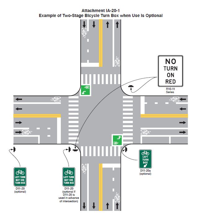
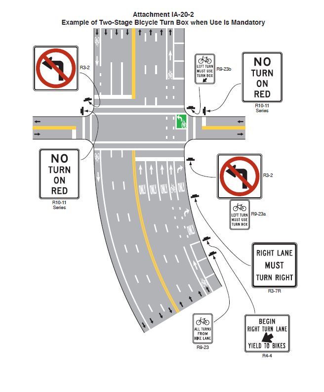
The two-stage bicycle turn box is an area set aside for bicyclists to queue to turn at a signalized intersection outside of the traveled path of motor vehicles and other bicycles. When using a two-stage bicycle turn box to make a left turn, a bicyclist would proceed on a green signal indication to the turn box on the right-hand side of the travel lanes, and then turn left within the turn box and wait for the appropriate signal indication on the cross street to proceed. Two-stage bicycle turn boxes can also be used with a left-side bicycle facility to facilitate bicyclists turning right. In addition to mitigating conflicts inherent in merging across traffic to turn, two-stage bicycle turn boxes reduce conflicts between bicycles and pedestrians and separate queued bicyclists waiting to turn from through bicyclists moving on the green signal.
The two-stage bicycle turn box has been a part of international practice for many years, and has been discussed in the United States since at least 1972, when it was featured as a design treatment in the State of California's Bikeway Planning Criteria and Guidelines, prepared by the Institute for Transportation and Traffic Engineering at the University of California, Los Angeles. The two-stage bicycle turn box was also featured in the 1974 AASHTO Guide for Bicycle Routes as an alternative to bicycle channelization at intersections.
The two-stage bicycle turn box described in this Interim Approval memorandum is a new traffic control device to the MUTCD and has been used in the United States only on an experimental basis through the MUTCD experimentation process, which is described in Section 1A.10 of the 2009 edition of the MUTCD.
Research on Two-Stage Bicycle Turn Boxes: Agencies around the country have shown significant interest in two-stage bicycle turn boxes, with 12 experiments approved under the 2009 edition of the MUTCD for a variety of government agencies. Data and observations were collected from agencies including the cities of Charlottesville, VA; Charlotte, NC; Atlanta, GA; San Francisco, CA; Toronto, ON, Canada; and many others. Although the Toronto data were collected internationally, the design and operation of the facilities in that study were functionally identical to those featured in this Interim Approval.
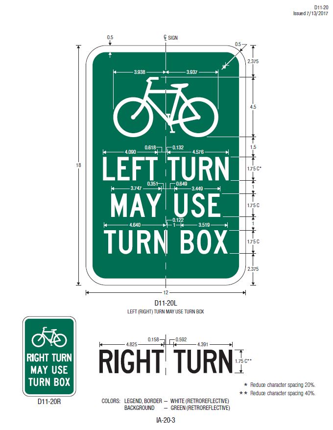
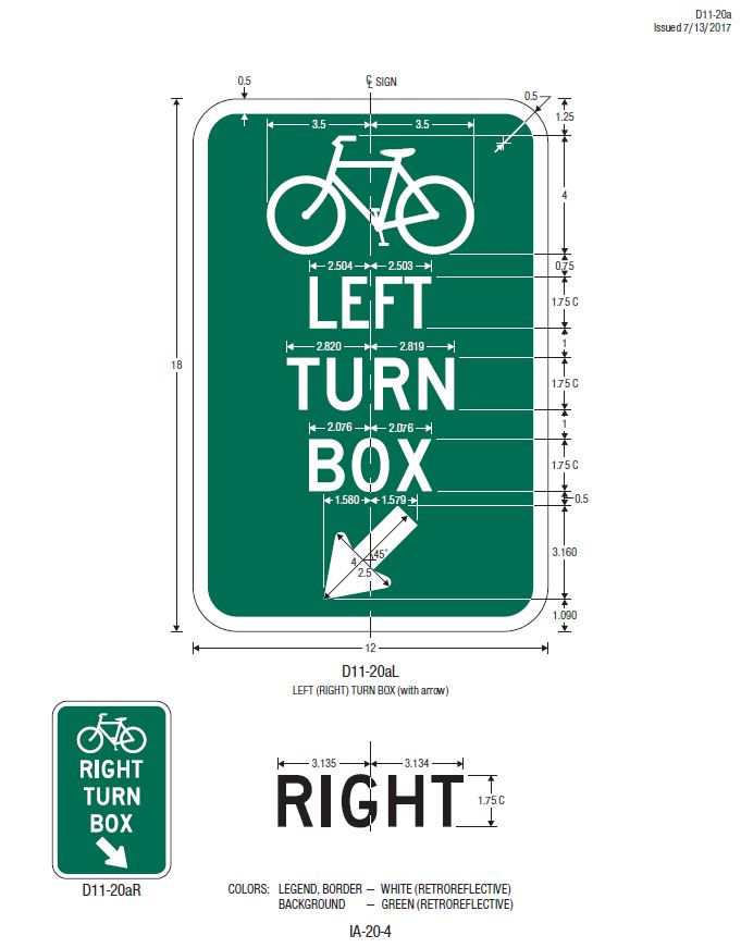
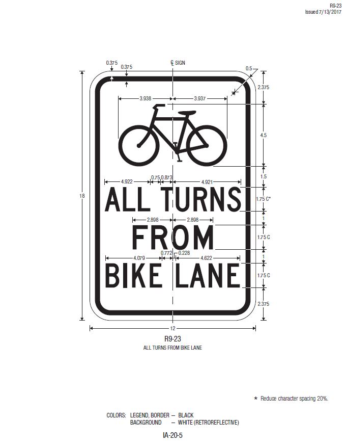
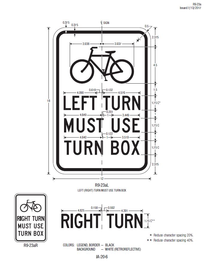
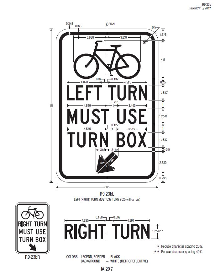
These experiments and other installations have used a relatively consistent design of a two-stage bicycle turn box that includes the following elements:
FHWA Evaluation of Results: The Office of Transportation Operations has reviewed the available data and considers the experimental two-stage bicycle turn box to be successful for the applications that were tested. Positive operational effects have been documented in the experiments after the installation of two-stage bicycle turn boxes. Most significantly, two-stage bicycle turn boxes have been shown to positively influence consistency in the operations of bicyclists making two-stage turns at intersections, a maneuver which had been occurring already at many of the studied locations.
In examining the data recorded at installed locations in the field, these improvements in consistency were noted at a majority of the installed sites. Where the two-stage bicycle turn boxes were installed, bicyclists were making a two-stage turn maneuver within or mostly within the turn box. At some study locations the only reason bicyclists were not using the two-stage bicycle turn box was that it was already fully occupied by other bicyclists making the same maneuver. Most of the sites where data were collected did not include guide signing to direct or inform bicycle traffic about the location of the turn box, and the data and observations suggest that signing is not required for proper understanding and operations of two-stage bicycle turn boxes.
The available collision data did not show an adverse impact on safety due to the installation of two-stage bicycle turn boxes. Two sites showed a decrease in collisions and two sites showed an increase, although the increases were limited to one collision in a 19-month analysis period.
The design of the two-stage bicycle turn box is not patented or proprietary and may be used by any jurisdiction that requests and obtains Interim Approval from the FHWA to use two-stage bicycle turn boxes in accordance with Paragraphs 14 through 22 of Section 1A.10 of the MUTCD. The FHWA believes that the two-stage bicycle turn box as detailed in this memorandum has a low risk of safety or operational concerns and the research analyzed shows that two-stage bicycle turn boxes can provide for a more orderly and consistent flow of traffic.
This Interim Approval does not create a new mandate compelling the use of two-stage bicycle turn boxes. This Interim Approval will allow agencies to install two-stage bicycle turn boxes to facilitate bicycle operations at intersections pending official MUTCD rulemaking.
Conditions of Interim Approval: The FHWA will grant permission for the optional use of two-stage bicycle turn boxes under this Interim Approval to any jurisdiction that submits a written request to the Office of Transportation Operations. A State may request Interim Approval for all jurisdictions in that State. Jurisdictions seeking permission to use two-stage bicycle turn boxes under this Interim Approval must agree to the following:
Any questions concerning this Interim Approval should be directed to Mr. Dave Kirschner at david.kirschner@dot.gov.
cc:
Associate Administrators
Acting Chief Counsel
Chief Financial Officer
Directors of Field Services
Director of Technical Services
Attachment(s) PDF Version, 1.3MB
|
United States Department of Transportation - Federal Highway Administration |
||