| FHWA Policy Memorandums |
 |
PDF Version, 606KB
You may need the Adobe® Reader® to view the PDFs on this page.
Memorandum |
|
| U.S. Department of Transportation | |
| Federal Highway Administration | |
| Subject: | INFORMATION: MUTCD – Interim Approval for Optional Use of Pedestrian-Actuated Rectangular Rapid-Flashing Beacons at Uncontrolled Marked Crosswalks (IA-21) | Date: | March 20, 2018 |
| From: | Martin C. Knopp Associate Administrator for Operations |
In Reply Refer To: | HOTO-1 |
| To: | Federal Lands Highway Division Directors Division Administrators |
Purpose: The purpose of this memorandum is to issue an Interim Approval for the optional use of Rectangular Rapid-Flashing Beacons (RRFB) as pedestrian-actuated conspicuity enhancements for pedestrian and school crossing warning signs under certain limited conditions. Interim Approval allows interim use, pending official rulemaking, of a new traffic control device, a revision to the application or manner of use of an existing traffic control device, or a provision not specifically described in the Manual on Uniform Traffic Control Devices for Streets and Highways (MUTCD). State and local agencies must request and receive permission to use this new Interim Approval, designated IA-21, from the Federal Highway Administration (FHWA) in accordance with the provisions of Section 1A.10 of the MUTCD before they can use the RRFB, even if prior approval had been given for Interim Approval 11 (IA-11), now terminated. The issuance of this new Interim Approval does not reinstate IA-11 either in whole or in part.
Background: The Florida Department of Transportation has requested that the FHWA issue an Interim Approval to allow the use of RRFBs as pedestrian-actuated conspicuity enhancements to supplement standard pedestrian and school crossing warning signs at uncontrolled marked crosswalks. The RRFB does not meet the current standards for flashing warning beacons as contained in the 2009 edition of the MUTCD, Chapter 4L, which requires a warning beacon to be circular in shape and either 8 or 12 inches in diameter, to flash at a rate of approximately once per second, and to be located no less than 12 inches outside the nearest edge of the warning sign it supplements. The RRFB uses rectangular-shaped high-intensity light-emitting-diode (LED)-based indications, flashes rapidly in a combination wig-wag and simultaneous flash pattern, and may be mounted immediately adjacent to the crossing sign.
Research on the RRFB: The City of St. Petersburg, Florida, experimented with the RRFB at 18 pedestrian crosswalks across uncontrolled approaches and submitted its final report in 2008. In addition to "before" data, the city collected "after" data at intervals for one year at all 18 sites and for two years at the first two implemented sites. For the first two sites, the city collected data for overhead and ground-mounted pedestrian crossing signs supplemented with standard circular yellow flashing warning beacons, for comparison purposes, before the RRFBs were installed. The data showed higher motorist yielding rates at crosswalks where the RRFBs had been installed in comparison to lower rates for standard warning beacons. The higher yielding rates were sustained even after two years of operation, and no identifiable negative effects were found. The St. Petersburg data also showed that drivers exhibit yielding behavior much farther in advance of crosswalks with RRFBs than with standard circular yellow flashing warning beacons.
In addition to the St. Petersburg locations, experimentation with RRFBs was also conducted at other uncontrolled marked crosswalks in Florida and other States. Data from locations other than St. Petersburg was limited, but did show results similar to those found in St. Petersburg.
The Texas Transportation Institute (TTI) conducted a Federally funded research project1 that developed and tested a new flash pattern for the RRFB that was shown to be at least as effective as the flash pattern that was initially tested in St. Petersburg, Florida, and that showed that mounting the RRFB unit above the sign was at least as effective as mounting the RRFB unit below the sign. In this project, the results were generally favorable, however there was a wide range of yielding rates, with some as low as 19 percent. This broad range indicates that there might be certain factors or characteristics of locations at which the RRFB might not be effective.
A separate project2 conducted by TTI examined data from multiple projects to determine various factors that influenced driver yielding rates at RRFB locations. In this project, the researchers found that intersection configuration, presence of a median refuge, crossing distance, approach to the crossing, and one-way vs. two-way traffic significantly affected the rate of driver yielding. Additional factors including posted speed limit, mounting of the beacons (overhead or roadside), and the type of crossing and sign—Pedestrian (W11-2) or School (S1-1) sign compared with the Trail Crossing (W11-15) sign—were also significant.
FHWA Evaluation of Results: The Office of Transportation Operations reviewed the available data in 2008 and considered the RRFB to be highly successful for the applications tested (uncontrolled marked crosswalks). The RRFB offers significant potential safety and cost benefits because it achieves high rates of compliance at a low relative cost in comparison to other more restrictive devices that provide comparable results, such as full midblock signalization or pedestrian hybrid beacons.
The FHWA granted interim approval status to the RRFB on July 16, 2008, and designated that action as Interim Approval 11 (IA-11).
The FHWA was later informed that the concept of the RRFB had been patented by a private company. Because patented traffic control devices are not allowed to be included in the MUTCD, are not allowed to be given interim approval status, and are not allowed to be a part of an official experiment, the FHWA terminated Interim Approval 11 on December 21, 2017.
The FHWA has confirmed that the patents on the RRFB device that was the subject of Interim Approval 11 have been expressly abandoned and the concept of the RRFB is now in the public domain. Because of this action, the RRFB is once again eligible for interim approval status and the FHWA is issuing this new Interim Approval for the RRFB.
Interim Approval 11 (IA-11) remains terminated. Agencies that previously had been approved to use RRFBs under IA-11 are not covered by this new Interim Approval to install new RRFBs. If agencies that had approval under IA-11 wish to continue to install new RRFBs, then they must submit a new request to the FHWA and agree to comply with the terms and conditions of IA-21.
This Interim Approval does not create a new mandate compelling installation of RRFBs, but will allow agencies to install this traffic control device, pending official MUTCD rulemaking, to provide a degree of enhanced pedestrian safety at uncontrolled marked crosswalks.
Conditions of Interim Approval: The FHWA will grant Interim Approval for the optional use of the RRFB as a pedestrian-actuated conspicuity enhancement to supplement standard pedestrian crossing or school crossing signs at uncontrolled marked crosswalks to any jurisdiction that submits a written request to the Office of Transportation Operations. A State may request Interim Approval for all jurisdictions in that State. Jurisdictions using RRFBs under this Interim Approval must agree to the following:
In addition, any agency that receives this approval must acknowledge agreement with the following:
The RRFB indication on the left-hand side shall be illuminated for approximately 50 milliseconds.
Both RRFB indications shall be dark for approximately 50 milliseconds.
The RRFB indication on the right-hand side shall be illuminated for approximately 50 milliseconds.
Both RRFB indications shall be dark for approximately 50 milliseconds.
Both RRFB indications shall be illuminated for approximately 50 milliseconds.
Both RRFB indications shall be dark for approximately 50 milliseconds.
Both RRFB indications shall be illuminated for approximately 50 milliseconds.
Both RRFB indications shall be dark for approximately 250 milliseconds.
Any questions concerning this Interim Approval should be directed to Mr. Duane Thomas at duane.thomas@dot.gov.
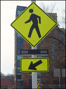
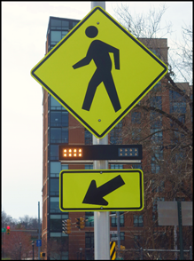
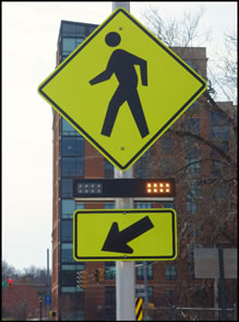
Figure 1. Example of an RRFB dark (left) and illuminated during the flash period (center and right) mounted with W11-2 sign and W16-7P plaque at an uncontrolled marked crosswalk.
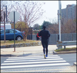
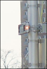
Figure 2. View of pilot light to pedestrian at shared-use path crossing with median refuge. Enlargement of pilot light at right.
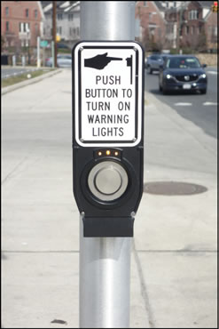
Figure 3. Example of pedestrian pushbutton and R10-25 sign with pilot light for pedestrian actuation.
cc:
Associate Administrators
Chief Counsel
Chief Financial Officer
Directors of Field Services
Director of Technical Services
1 Fitzpatrick, K., R. Avelar, M. Pratt, M. Brewer, J. Robertson, T. Lindheimer, and J. Miles. Evaluation of Pedestrian Hybrid Beacons and Rapid Flashing Beacons. Report No. FHWA-HRT-16-040, pp. 88-106. Texas Transportation Institute, College Station, Texas. July 2016. https://www.fhwa.dot.gov/publications/research/safety/16040/index.cfm [Return to Note 1]
2 Fitzpatrick, K., M. Brewer, R. Avelar, and T. Lindheimer. Will You Stop for Me? Roadway Design and Traffic Control Device Influences on Drivers Yielding to Pedestrians in a Crosswalk with a Rectangular Rapid-Flashing Beacon. Report No. TTI-CTS-0010. Texas A&M Transportation Institute, College Station, Texas. June 2016. https://static.tti.tamu.edu/tti.tamu.edu/documents/TTI-CTS-0010.pdf [Return to Note 2]
|
United States Department of Transportation - Federal Highway Administration |
||