 |
PDF Version, 644KB
You will need the Adobe Acrobat Reader to view the PDF on this page.
![]()
U.S. Department of Transportation
Federal Highway Administration
1200 New Jersey Avenue, SE.
Washington, D.C. 20590
July 10, 2009
In Reply Refer To: HOTO-1
Thomas M. Peters, P.E.
Tort Claims and Traffic Standards Manager
Minnesota Department of Transportation
1500 West County Road B2, MS 725
Roseville, MN 55113-3174
Dear Mr. Peters:
Thank you for your June 9 letter requesting approval to experiment with in-roadway lights in conjunction with the operation of a Priced Dynamic Shoulder Lane (PDSL) that is planned for implementation on Interstate 35W in Minneapolis under an Urban Partnership Agreement.
As shown in Exhibit 2 accompanying your request, the in-roadway lights would substitute for painted lines on northbound I-35W in the area between 42nd Street and 38th Street where the transition into the left shoulder PDSL will occur. In this section of roadway, when the PDSL is open, a series of white in-roadway lights would be steadily illuminated and would substitute for broken white lane line markings for a continuation of the left-most lane into the PDSL. When the PDSL is closed, a series of yellow in-roadway lights would be steadily illuminated and would substitute for a solid yellow left edge line in the taper where the left-most lane ends and traffic in that lane must merge.
It is our interpretation of Part 3 of the Manual on Uniform Traffic Control Devices (MUTCD) that the in-roadway lights you propose to install on the project are considered internally-illuminated raised pavement markers (RPMs), because they are steadily illuminated and not operated in a flashing pattern. As long as the lights are installed with the number and spacing pattern that is specified in Section 3B.14 of the MUTCD for RPMs substituting for a broken line and for a solid line, respectively, and as long as they are steadily illuminated, the lights would be in compliance with the MUTCD and therefore experimentation approval for such use is not required.
However, in reviewing the exhibits that accompanied your experimentation request, and in our staff's discussion of those exhibits with you and other members of your staff during a conference call on June 30, we have noted certain other elements of your planned pavement markings for the PDSL that are of significant concern to the Federal Highway Administration (FHWA):
If your department wishes to proceed with the PDSL project without changing the existing yellow left edge line to white, it will be necessary to request FHWA experimentation approval for that noncompliant use of a yellow line. Such a request will need to include a comprehensive research plan to evaluate whether the presence of the yellow line is confusing to drivers and whether it impacts the ability of daily PDSL users to react properly to yellow lines at other locations where the color is critical to communicating a wrong-way travel message. Such an evaluation would need to include human factors testing (perhaps in a simulator) as well as field data collection and surveys.
Please note that we have assigned this matter the following official interpretation number and title: "3-230(I) - Illuminated RPMs - MN DOT." Please refer to this number in any future correspondence. If further discussion of the pavement marking elements of your PDSL project is needed, please feel free to contact Mr. Scott Wainwright at scott.wainwright@dot.gov or by telephone at 202-366-0857. Thank you for your interest in traffic operations and safety.
Sincerely yours,
Hari Kalla
Acting Director, Office of Transportation Operations
State of Minnesota
Department of Transportation
Office of Transportation Security and Operations
1500 West County Road B2, MS 725
Roseville, MN 55113-3174
Phone 651.582.1000 FAX 651.215.0409
June 9, 2009
Mr. Paul Pisano
Acting Director, Office of Transportation Operations
Federal Highway Administration
Office of Transportation Operations
400 Seventh Street, SW, HOTO
Washington, DC 20590
Re: Request to Experiment - In-Roadway Lighting for Urban Partnership Agreement (UPA) Project on I-35W Project
Dear Mr. Pisano,
In accordance with the 2003 Manual on Uniform Traffic Control Devices (MUTCD), I am requesting permission to experiment with the above traffic control device. Under the authority of the MUTCD, the Minnesota Department of Transportation (Mn/DOT) has authorized and published a Minnesota version of this manual (MN MUTCD). The current MN MUTCD edition is dated July, 2005.
Mn/DOT has received federal funds for the UPA project to reduce traffic congestion in the Twin Cities. As part of the project, Mn/DOT is implementing a Priced Dynamic Shoulder Lane (PDSL). The PDSL will be approximately three miles long beginning at the end of the BRT/HOV/HOT lane at 38th Street and will continue to downtown Minneapolis. The left shoulder will be the PDSL and will be open to BRT/HOV/HOT lane traffic during peak periods and closed to all traffic when traffic is free flowing.
Mn/DOT will open and close the PDSL using the combination of static signing, dynamic signing and pavement markings. The static signing will be located on an overhead sign structure at the beginning of the PDSL and continue every ½ mile until the end of the PDSL.
Enclosed are the documents that provide a more complete description of our request regarding the use of the In-Roadway Lighting, its location, layout configuration and static signs. Mn/DOT will measure the effectiveness of the In-Roadway Lighting for two years using loop detector data and camera video.
It is with this Request to Experiment that Mn/DOT would like to alleviate driver confusion regarding whether the PDSL is open or closed. The Florida Department of Transportation had several severe crashes when they opened their UPA project. It is with this knowledge and understanding that Mn/DOT would like to learn from their experience and be proactive when it comes to driver's expectation and safety.
Sincerely,
/s/ Thomas M. Peters
Thomas M. Peters, P.E.
Tort Claims & Traffic Standards Engineer
Enclosures
Request to Experiment: In-Roadway Lighting for Urban Partnership Agreement (UPA) Project on I-35W
The Minnesota Department of Transportation (Mn/DOT) is requesting permission to experiment with In-Roadway Lighting on a section of roadway on northbound I-35W in Minneapolis. It is part of the Urban Partnership Agreement (UPA) project which is on schedule to open by September 2009.
Background
Mn/DOT received federal funds for the UPA project to reduce traffic congestion in the Twin Cities. As part of the project Mn/DOT is implementing a Priced Dynamic Shoulder Lane (PDSL). The PDSL will be approximately three miles long beginning at the end of the BRT/HOV/HOT lane at 38th Street and will continue to downtown Minneapolis. The left shoulder will be the PDSL and will be open to BRT/HOV/HOT lane traffic during peak periods and closed to all traffic when traffic is free flowing.
PDSL Operations
South of the PDSL the left lane is a BRT/HOV/HOT lane. During the peak periods, the BRT/HOV/HOT traffic will continue straight into PDSL all the way to downtown Minneapolis. During free flow traffic conditions, the PDSL will be closed and BRT/HOV/HOT lane traffic will be required to merge right into mainline traffic. Exhibits 1 and 2 attached show the lane configuration when the PDSL is open and closed.
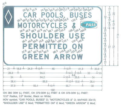
Mn/DOT will open and close the PDSL using the combination of static signing, dynamic signing and pavement marking. The static signing (see attached Exhibit 3 for shoulder use regulatory sign) will be located on an overhead sign structure at the beginning of the PDSL and continue every ½ mile until the end of the PDSL. Directly under each of the regulatory static signs is a dynamic sign which will either have a green arrow when open or a red "X" when closed. Exhibits 1 and 2 attached show the static and dynamic signing when the PDSL is open and closed.
Why In-Roadway Lighting
The pavement marking plans show a broken yellow edge line merging the BRT/HOV/HOT lane traffic when the PDSL is closed. When the PDSL is open through, this traffic will drive directly over the broken yellow strip, thus causing excessive wear and tear of the marking. This design is shown in Exhibit 1. Mn/DOT created a computer simulation of traffic driving northbound on I-35W as it enters the PDSL area of the project. The simulation is based on the design plans and shows the left lane transitioning from a BRT/HOV/HOT lane to the PDSL lane. It has the yellow broken stripe across that lane to connect the two yellow edge lines. The yellow broken stripe directs merging traffic when the PDSL is closed however it is not strong enough message to indicate traffic MUST merge when the PDSL is closed. In part, the white lane line separating the two lanes of traffic will be missing for approximately 1000ft.
The current pavement marking design with the painted yellow broken merge stripe may cause some confusion to drivers on whether they can or cannot cross the yellow broken merge stripe. The overhead signing will change when the PDSL is open or closed, but the pavement markings would remain the same. For this reason Mn/DOT is proposing to use In-Roadway Lighting. Since the In-Roadway Lighting is dynamic it allows for use of the yellow lights for the merge line when the PDSL is closed and white lights on the lane line when the PDSL is open. The individual In-Roadway Lights will be placed closely enough to each other to appear to traffic as a solid yellow merge line informing drivers the PDSL lane is closed. This would be consistent with the painted solid yellow taper. When the PDSL is open, the In-Roadway Lighting for the closed PDSL will turn off and an In-Roadway Lighting broken white stripe will turn on, separating the PDSL from the left lane of traffic. The In-Roadway Lighting will correspond with the dynamic signs controlled by Mn/DOT's Regional Traffic Management Center.
Currently, the Minnesota Manual on Uniform Traffic Control Devices (MNNUTCD) does not cover In-Roadway Lighting substituting for a pavement marking. There are sections coving raised pavement markers in the MNMUTCD - Sections 3B.11, 3B.13, and 3B.14. However, a raised pavement maker is defined in Section 3B.11 as having a height of at least 10 mm (0.4 in). These In-Roadway Lights are designed to be installed flush to the pavement surface because of snowplow concerns. Chapter 4L in the MNMUTCD discusses In-Roadway Lights. In-Roadway Lights are defined as being up to 19 mm (0.75 in) above the roadway surface, so the lighting on this project clearly falls under that umbrella. However, the MNMUTCD only discusses In-Roadway Lights in the application of supplementing, not substituting for, existing crosswalk markings with applicable warning signs. There is not any language or a figure in the MNMUTCD showing a standard for the use of In-Roadway Lighting substituting for a pavement marking. For these reasons Mn/DOT is requesting authorization for experimentation on I-Roadway Lighting on I-35W. The request for experiment would be to allow the Mn/DOT to use In-Roadway Lighting at the transition point of the BRT/HOV/HOT lane to PDSL. The In-Roadway Lighting will be used for a length of approximately 1,000 feet on the freeway in only one location, the beginning of the PDSL.
Mn/DOT would like to alleviate driver confusion regarding whether the PDSL is open or closed. In-Roadway Lighting that can be turned on or off in coordination with the dynamic signs is the solution. The Florida Department of Transportation had several severe crashes when they opened their UPA project. Mn/DOT would like to learn from their experience and be proactive when it comes to drivers's expectation and safety.
Demonstration
Mn/DOT would install the In-Roadway Lighting according to the manufacturer's recommendation. However, no exact spacing of lights has been given. Therefore, Mn/DOT requested two strings of lights from the manufacturer in order for Mn/DOT staff to experiment with. On of the main tasks was to determine spacing of lights for both the yellow and white lines. A daytime demonstration was held and local FHWA staff attended. A string of lights was set up on roadway at Mn/DOT's Mn/ROAD Research Facility. Staff was able to drive vehicles next to the lights at freeway speed, change the spacing of the lights and drive it again. It was performed in this same manner later that night after dark.
Staff agreed that spacing of 15 ft between individual lights on the yellow taper line achieved the desired results, the appearance of a solid line. In order to simulate the broken white line, it was determined that a cycle of a 3 lights evenly spaced over 10 ft. then a 40 ft gap of no lights achieves the results we for the white line will be used for the white lights. Each 10 ft line would have 3 lights spaced evenly.
Evaluation
Mn/DOT will measure the effectiveness of the In-Roadway Lighting for two years using loop detector data and camera video. There will be a loop detector placed at the beginning of the PDSL which will record the number of vehicles using the PDSL lane. The traffic counts will have the time associated with when vehicles cross it so which will show whether vehicles are in compliance with PDSL being opened or closed. There is a study camera installed at the beginning of the PDSL lane, at the overhead structure at 38th Street. This camera will be constantly recording video at the PDSL. This visual will show how drivers are reacting to the In-Roadway Lighting indicating when the PDSL is opened or closed. There are also traffic cameras at 35th Street and 42nd Street. These cameras can also be used to visually monitor traffic at the PDSL from different angles and distances.
Exhibit 1: Current Pavement Markings - Painted Merge Line
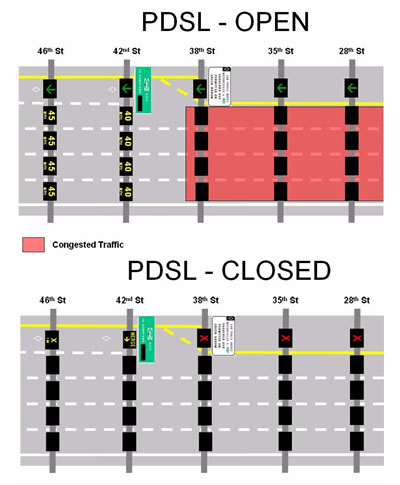
Exhibit 2: Proposed Pavement Marking Design with In-Road Lighting
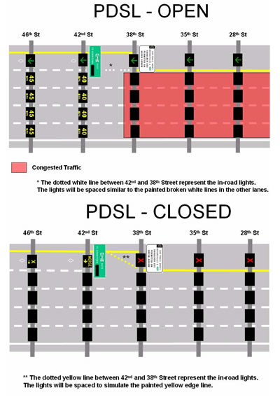
Exhibit 3: Static Regulatory Sign
|
United States Department of Transportation - Federal Highway Administration |
||