 |
PDF Version, 3MB
PDF files can be viewed with the Acrobat® Reader®.
![]()
U.S. Department of Transportation
Federal Highway Administration
1200 New Jersey Avenue, SE.
Washington, D.C. 20590
June 13, 2012
In Reply Refer To: HOTO-1
Mr. Chris Peddie,
President
Spot Devices
1455 Kleppe Lane
Sparks, NV 89431
Dear Mr. Peddie:
Thank you for your letter of June 4 requesting an official interpretation regarding the flashing pattern for the Rectangular Rapid Flashing Beacon (RRFB).
As you mention in your letter, Item 5b of the "Conditions of Interim Approval" in our original Interim Approval 11 memorandum dated July 16, 2008 (https://mutcd.fhwa.dot.gov/resources/interim_approval/ia11/ia11_rrfb_iapmemo.pdf) says the following about the RRFB's flashing pattern: "During each of its 70 to 80 flashing periods per minute, one of the yellow indications shall emit two rapid pulses of light and the other yellow indication shall emit three rapid pulses of light." At the time that this interim approval was issued, we were under the impression that the RRFBs that had generated high compliance rates in the official experiments used a 2/3 flashing pattern.
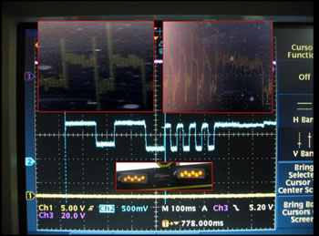
We subsequently received a request for an official interpretation of the RRFB flashing pattern in an e-mail message from Ron Van Houten on July 15, 2010. Mr. Van Houten was one of the researchers who participated in some of the experiments in Florida that led to the interim approval. In his e-mail message (see copy attached to this letter), Mr. Van Houten informed us that Mr. Carl Morse, who manages the Florida DOT's traffic control device testing laboratory in Tallahassee, had used an oscilloscope to analyze the actual on/off pattern for the two lights of the type of RRFB that was used in the actual field experimentations and found that the flashing pattern was something other than a 2/3 flashing pattern. Mr. Van Houten's message included an photograph of Mr. Morse's oscilloscope output.
Mr. Van Houten's e-mail message stated that the flash pattern that was evaluated in the RRFB experiments was actually "two slow followed by four rapid flashes." Mr. Van Houten requested that, "Since the 2/4 pattern is what we evaluated, and is what is manufactured, it is my recommendation that the standard be changed to reflect this."
In response to Mr. Van Houten's request for an official interpretation, we issued Official Interpretation 4(09)-4 (I) (https://mutcd.fhwa.dot.gov/resources/interpretations/pdf/4_09_4.pdf) on August 3, 2010. In our interpretation, we stated that, "based on the information submitted, we concur that units for which an oscilloscope detects a flash pattern of two pulses in one of the yellow indications followed by four pulses in the other yellow indication meet the intent of item 5.b., as long as the units appear to human observers with 20:40 visual acuity or better to flash in the specified two-three pattern."
In your letter, you mention that the inclusion of language in our Official Interpretation 4(09)-4 (I) regarding how the RRFB flashing pattern appears to human observers adds a subjective element to the provisions of a Standard statement, which is inappropriate. We therefore agree with you that the Standard statement should be based on the actual flashing pattern that was used in the RRFB experiments, and not upon what the flashing pattern appears to be to a human observer.
Your letter resulted in our taking a closer look at the e-mail message that we received from Mr. Van Houten on July 15, 2010, and at the photograph of Mr. Morse's oscilloscope output. In doing so, we noticed that describing the flashing pattern as "two pulses in one of the yellow indications followed by four pulses in the other yellow indication" is incorrect. Mr. Van Houten describes the flashing pattern shown in the photograph of the oscilloscope output as "the left LED flashed two times in a slow volley each time it was energized (124 milliseconds on and 76 milliseconds off per flash) followed by the right LED, which flashed four times in a rapid volley when energized (25 milliseconds on and 25 milliseconds off per flash) and then a longer 200 milliseconds flash." Mr. Van Houten's description of the flashing pattern shown in the photograph of the oscilloscope output is accurate and the important fact to notice is that the right LED actually flashes five times (four rapid flashes followed by one long flash) rather than four times.
It is the FHWA's official interpretation that Item 5b of the "Conditions of Interim Approval" in our original Interim Approval 11 memorandum dated July 16, 2008 should be replaced by the following language:
b. As a specific exception to 2003 MUTCD Section 4K.01 requirements for the flash rate of beacons, RRFBs shall use a much faster flash rate. Each of the two yellow indications of an RRFB shall have 70 to 80 periods of flashing per minute and shall have alternating, but approximately equal, periods of flashing light emissions and dark operation. During each of its 70 to 80 flashing periods per minute, the yellow indications on the left side of the RRFB shall emit two slow pulses of light after which the yellow indications on the right side of the RRFB shall emit four rapid pulses of light followed by a long pulse.
For recordkeeping purposes, we have assigned the following official ruling number and title: "4(09)-21 (I) — Clarification of RRFB Flashing Pattern." Please refer to this number in any future correspondence regarding this topic.
This official ruling supersedes the previous Official Interpretation 4(09)-4 (I) dated August 3, 2010, which is now considered to be null and void.
Thank you for your interest in improving the clarity of the provisions contained in the MUTCD.
Sincerely yours,
Original signed by:
Mark R. Kehrli
Director, Office of Transportation Operations
From: ron.vanhouten@wmich.edu on behalf of Dr. Ron Van Houton
To: Wainwright, Scott (FHWA)
Cc: Rick Jones
Subject: Fwd: Flashing Patten
Date: Thursday, July 15, 2010 2:02:35 PM
Attachments: flash pattern scope image.jpg
ATT632376.htm
Enhancer4xSlower.wmv
Att632377.htm
Scott: I have recently learned that the flash pattern we evaluated actually is two slow followed by four rapid flashes. Carl Morse has looked on a scope and the following is what has been determined: Each side of the LED flasher illuminated in a wig-wag sequence (left and then right). The left LED flashed two times in a slow volley each time it was energized (124 ms on and 76 ms off per flash) followed by the right LED, which flashed four times in a rapid volley when energized (25 ms on and 25 ms off per flash) and then a longer 200 ms flash. The total cycle length is 800 ms. The e-mail below from Rick Jones states that the units submitted to FDOT for testing had the same flash pattern as those evaluated in our research.
I have attached the scope tracing, and slow motion video of the flash pattern. Even in slow motion it appears like two slow flashes followed by three fast flashes but the eyes is deceived. This flash pattern is likely an SAE standard. Carl noted another LED flasher manufacture used the same pattern on flashers made for a different application. Since the 2/4 pattern is what we evaluated, and is what is manufactured, it is my recommendation that the standard be changed to reflect this. Thanks, Ron
From: "Richard D. Jones" <rdjones@stopexperts.com>
Date: July 15, 2010 12:52:27 PM EDT
To: ron.vanhouten@wmich.edu
Cc: Kristine@stopexperts.com
Subject: Flashing Pattern
Good afternoon Ron. In regards to our telephone conversation, here is what I now know to be factual. The large LED's on my Enhancer units are manufactured by Whelen Engineering, Co. What every human eye that I have spoken with see's when the system starts its wig-wag flashing sequence, is a slow 2 type flash and a fast 3 type flash sequence - the fast 3 is actually a fast 4. This was identified by FDOT's Carl Morris on a scope.
Whelen and I really never spoke to much about the flash rate - because it clearly looks like a 3 flash, as the 2 looks like a 2 flash, why would I ask them is this a 2 flash and 3 flash? Anyway, with me having Systems across the country, I'm very concerned due to the language in the Interim Approval clearly states a "3 flash" (which is what I've been telling everybody since day one) - can the language be modified simply to state "…a slow 2 flash and then a fast 3 to 4 flash".
With this discovery, the engineers over at Whelen have confirmed that this flash pattern that I've using for 5 years, was created in the early mid 90's, and has never changed. What you and others studied, was in reality a fast 4 flash. The packaging on these LED's (model number TIR 500 Series), show a setting for a "double flash", (the slow 2 flash) the (what I thought was a fast 3 has always been marked) as "signal alert" flashing sequence, which again is what I thought was a fast 3.
If there is anything else that I can do to help clear this up. please let me know.
Thanks Ron. -rj
|
United States Department of Transportation - Federal Highway Administration |
||