
Technical Provisions for AFADs
Revised 1/27/2005
Section 1: Automated Flagger Assistance Devices - General
Support:
Automated Flagger Assistance Devices (AFADs) enable a flagger(s) to be positioned out
of the lane of traffic and are used to control road users through temporary traffic control
zones. These devices are designed to be remotely operated either by a single flagger at
one end of the TTC zone or at a central location or by separate flaggers near each
device's location.
The provisions for the design and use of AFADs described in this Interim Approval are based on experimentation with two types of AFADs:
- An AFAD that uses a remotely controlled STOP/SLOW sign on either a trailer or a movable cart system to alternately control right-of-way.
- An AFAD that uses remotely controlled red and yellow lenses and a gate arm to alternately control right-of-way.
AFADs might be appropriate under certain conditions for daytime work activities where they are set up and then removed each day or for some nighttime work activities. Typical applications include TTC activities such as, but not limited to:
- Bridge maintenance;
- Haul road crossings; and
- Pavement patching.
Standard:
AFADs shall only be used in situations where there is only one lane of approaching traffic in the direction to be controlled.
When used at night, the AFAD location shall be illuminated in accordance with Section 6E.05.
Guidance:
AFADs should only be used when determined to be appropriate based on an engineering study.
The maximum distance between two AFADs controlling opposing directions of traffic should be 300 m (1,000 ft), unless a longer distance is justified by an engineering study. Minimum or maximum traffic volume thresholds for the applicability of AFAD usage should be based upon an engineering study conducted by the agency authorizing their use.
Standard:
Because AFADs are not traffic control signals, they shall not be used as a substitute for or a replacement for a continuously operating temporary traffic control signal as
described in Section 6F.80.
If used on the National Highway System, AFADs shall meet the crashworthy performance criteria contained in the National Cooperative Highway Research Program (NCHRP) Report 350, "Recommended Procedures for the Safety Performance Evaluation of Highway Features" (see Section 6F.01).
Guidance:
If used on highways that are not on the National Highway System, AFADs should meet
the NCHRP Report 350 crashworthy performance criteria.
If used, AFADs should be located in advance of lane closure tapers and downstream from the point where approaching traffic is to stop in response to the device.
Standard:
If used, AFADs shall be placed so that all of the signs and other items controlling traffic movement are readily visible to the driver of the initial approaching vehicle with advance warning signs alerting other approaching traffic to be prepared to stop.
If used, an AFAD shall be operated only by a qualified flagger (see Section 6E.01) who has been trained on the operation of the AFAD. The flagger(s) operating the AFAD(s) shall not leave the AFAD(s) unattended at any time while the AFAD(s) is being used to assign the right-of-way.
The use of AFADs shall conform to one of the following methods:
- An AFAD at each end of the TTC zone (Method 1); or
- An AFAD at one end of the TTC zone and a flagger at the opposite end (Method 2).
Except as noted in the Option below, two flaggers shall be used when using either Method 1 or Method 2.
Option:
A single flagger may simultaneously operate two AFADs (Method 1) or may operate a
single AFAD on one end of the TTC zone while being the flagger at the opposite end of
the TTC zone (Method 2) if all three of the following conditions are present:
- The flagger has an unobstructed view of the AFAD(s);
- The flagger has an unobstructed view of approaching traffic in both directions; and
- The AFADs are less than 240 m (800 ft) apart.
Guidance:
When an AFAD is used, the advance warning signing should include a ROAD WORK
AHEAD (W20-1) sign, a ONE LANE ROAD (W20-4) sign, and a BE PREPARED TO
STOP (W3-4) sign.
When an AFAD is not in use, it should be removed from its normal operating position and stored in a manner that reduces the possibility of it being impacted by run-off-the-road vehicles.
Standard:
When the AFAD is not in use, the signs associated with the AFAD, both at the AFAD location and in advance, shall be removed or covered.
Guidance:
A State or local agency that elects to use AFADs should adopt a policy governing AFAD
applications that, as a minimum, complies with the requirements of this Interim Approval
and the MUTCD. The policy should also consider more detailed and/or more restrictive
requirements for AFAD use, such as the following:
- Conditions applicable for the use of Method 1 and Method 2 AFAD operation;
- Volume criteria;
- Maximum distance between AFADs;
- Conflicting lenses/indications monitoring requirements;
- Fail safe procedures;
- Additional signing and pavement markings;
- Application consistency;
- Larger signs or lenses to increase visibility; and
- Use of backplates.
Section 2. STOP/SLOW Automated Flagger Assistance Devices
Standard:
A STOP/SLOW Automated Flagger Assistance Device (AFAD) shall include a
STOP/SLOW sign that alternately displays the STOP face and the SLOW face of a
STOP/SLOW paddle without the need for a flagger in the immediate vicinity of the
AFAD or on the roadway.
The AFAD's STOP/SLOW sign shall have an octagonal shape, shall be fabricated of rigid material, and shall be mounted with the bottom of the sign a minimum of 1.8 m (6 ft) above the pavement on an appropriate support. The size of the STOP/SLOW sign shall be at least 600 x 600 mm (24 x 24 in) with letters at least 200 mm (8 in) high. The background of the STOP face shall be red with white letters and border. The background of the SLOW face shall be diamond shaped and orange with black letters and border. Both faces of the STOP/SLOW sign shall be retroreflectorized.
The AFAD's STOP/SLOW sign shall have a means to positively lock, engage, or otherwise maintain the sign assembly in a stable condition when set in the STOP or SLOW position.
The AFAD's STOP/SLOW sign shall be supplemented with active conspicuity devices by incorporating either:
- White or red flashing lights within the STOP face and white or yellow flashing lights within the SLOW face meeting the provisions contained in Section 6E.03; or
- A Stop Beacon (see Section 4K.05) mounted no more than 600 mm (24 in) above the STOP face and a Warning Beacon (see Section 4K.03) mounted no more than 600 mm (24 in) above, below, or to the side of the SLOW face. The Stop Beacon shall not be flashed or illuminated when the SLOW face is displayed, and the Warning Beacon shall not be flashed or illuminated when the STOP face is displayed. Except for the mounting locations, the beacons shall conform to the provisions of Chapter 4K.
Option:
Type B warning light(s) (see Section 6F.78) may be used in lieu of the Warning Beacon
during the display of the SLOW face of the AFAD's STOP/SLOW sign.
Standard:
If Type B warning lights are used in lieu of a Warning Beacon, they shall flash
continuously when the SLOW face is displayed and shall not be flashed or illuminated when the STOP face is displayed.
Option:
The faces of the AFAD's STOP/SLOW sign may include louvers to improve the stability of the device in windy or other adverse environmental conditions.
Standard:
If louvers are used, the louvers shall be designed such that the aspect of the sign face to approaching traffic is a full sign face at a distance of 15 m (50 ft) or greater.
Guidance:
The STOP/SLOW AFAD should include a gate arm that descends to a down position across the approach lane of traffic when the STOP face is displayed and then ascends to an upright position when the SLOW face is displayed.
Option:
In lieu of a stationary STOP/SLOW sign with a separate gate arm, the STOP/SLOW sign
may be attached to a mast arm that physically blocks the approach lane of traffic when
the STOP face is displayed and then moves to a position that does not block the approach
lane when the SLOW face is displayed.
Standard:
If used, the gate arm or mast arm shall be covered with alternating red and white
retroreflective stripes at 150 mm (6 in) intervals measured horizontally. When the arm is in the down position blocking the approach lane:
- The minimum vertical aspect of the arm and sheeting shall be 50 mm (2 in).
- The stripes shall slope downward at an angle of 45 degrees from the upper right to the lower left on the side of the arm facing stopped traffic, and from the upper left to the lower right on the side of the arm facing moving traffic in the oncoming direction.
- The end of the arm shall reach at least to the center of the lane being controlled.
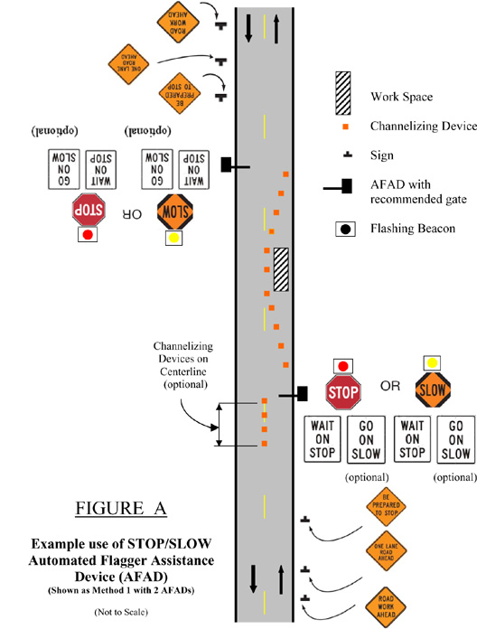
A WAIT ON STOP (R1-7) sign (see Figure A) shall be displayed to road users approaching the AFAD.
Option:
A GO ON SLOW (R1-8) sign (see Figure A) may also be displayed to road users approaching the AFAD.
Figure A Example Use of STOP/SLOW Automated Flagger Assistance Device (AFAD)
Standard:
The GO ON SLOW sign, if used, and the WAIT ON STOP sign shall be positioned on the same support structure as the AFAD or immediately adjacent to the AFAD such that they are in the same direct line of view of approaching traffic as the sign faces of the AFAD. Both signs shall have black legends and borders on white backgrounds. Each of these signs shall be rectangular in shape and each shall be at least 600 x 750 mm (24 x 30 in) in size with letters at least 150 mm (6 in) high.
To stop road users, the AFAD shall display the STOP face and the red or white lights within the STOP face shall flash or the Stop Beacon shall flash. To permit stopped road users to proceed, the AFAD shall display the SLOW face and the yellow or white lights within the SLOW face shall flash or the Warning Beacon or the Type B warning lights shall flash.
If STOP/SLOW AFADs are used to control traffic in a one-lane, two-way TTC zone, safeguards shall be incorporated to prevent the flagger(s) from simultaneously displaying the SLOW face at each end of the TTC zone. Additionally, the flagger shall not display the AFAD's SLOW face until all oncoming vehicles have cleared the one-lane portion of the TTC zone.
Section 3. Red/Yellow Lens Automated Flagger Assistance Devices
Standard:
If used, a Red/Yellow Lens Automated Flagger Assistance Device (AFAD) (see Section 1) shall alternately display a steadily illuminated CIRCULAR RED lens and a flashing CIRCULAR YELLOW lens to control traffic without the need for a flagger in the immediate vicinity of the AFAD or on the roadway.
Red/Yellow Lens AFADs shall have at least one set of CIRCULAR RED and CIRCULAR YELLOW lenses that are 300 mm (12 in) in diameter. Unless otherwise stated in this Section, the lenses and their arrangement, CIRCULAR RED on top and CIRCULAR YELLOW below, shall conform to the applicable provisions for traffic signal indications in Part 4 of the MUTCD. If the set of lenses is post-mounted, the bottom of the housing (including brackets) shall be at least 2.1 m (7 ft) above the pavement. If the set of lenses is located over any portion of the highway that can be used by motor vehicles, the bottom of the housing (including brackets) shall be at least 4.6 m (15 ft) above the pavement.
Option:
Additional sets of CIRCULAR RED and CIRCULAR YELLOW lenses, located over the
roadway or on the left side of the approach and operated in unison with the primary set,
may be used to improve visibility and/or conspicuity of the AFAD.
Standard:
A Red/Yellow Lens AFAD shall include a gate arm that descends to a down position
across the approach lane of traffic when the steady CIRCULAR RED lens is illuminated and then ascends to an upright position when the flashing CIRCULAR YELLOW lens is illuminated. The gate arm shall be covered with alternating red and white retroreflective stripes at 150 mm (6 in) intervals measured horizontally. When the gate arm is in the down position:
- The minimum vertical aspect of the arm and sheeting shall be 50 mm (2 in).
- The stripes shall slope downward at an angle of 45 degrees from the upper right to the lower left on the side of the arm facing stopped traffic, and from the upper left to the lower right on the side of the arm facing moving traffic in the oncoming direction.
- The end of the arm shall reach at least to the center of the lane being controlled.
A Stop Here On Red (R10-6 or R10-6a) sign (see Section 2B.45) shall be installed on the right-hand side of the approach at the point at which drivers are expected to stop when the steady CIRCULAR RED lens is illuminated (see Figure B.)
Figure B Example Use of RED/YELLOW Lens Automated Flagger Assistance Device (AFAD)
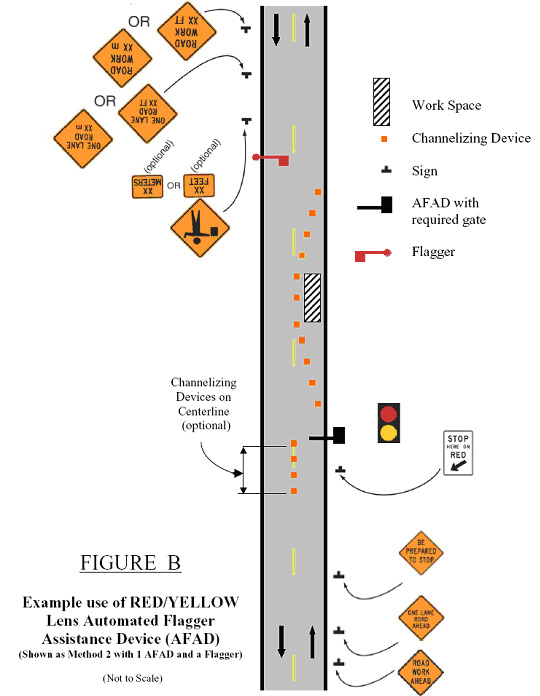
To stop road users, the AFAD shall display a steadily illuminated CIRCULAR RED lens and the gate arm shall be in the down position. To permit road users to proceed, the AFAD shall display a flashing CIRCULAR YELLOW lens and the gate arm shall be in the upright position.
If Red/Yellow Lens AFADs are used to control traffic in a one-lane, two-way TTC zone, safeguards shall be incorporated to prevent the flagger(s) from actuating a simultaneous display of a flashing CIRCULAR YELLOW lens at each end of the TTC zone. Additionally, the flagger shall not actuate the AFAD's display of the flashing CIRCULAR YELLOW lens until all oncoming vehicles have cleared the one-lane portion of the TTC zone.
A change interval shall be provided as the transition between the display of the flashing CIRCULAR YELLOW indication and the display of the steady CIRCULAR RED indication. During the change interval, the CIRCULAR YELLOW lens shall be steadily illuminated. The gate arm shall remain in the upright position during the display of the steadily illuminated CIRCULAR YELLOW change interval.
A change interval shall not be provided between the display of the steady CIRCULAR RED indication and the display of the flashing CIRCULAR YELLOW indication.
Guidance:
The steadily illuminated CIRCULAR YELLOW change interval should have a duration of at least 5 seconds, unless a different duration, within the range of durations recommended by Section 4D.10, is justified by engineering judgment.