2009 Edition Part 3 Figure 3B-10. Examples of Applications of Freeway and Expressway Lane-Drop Markings (Sheet 3 of 5)

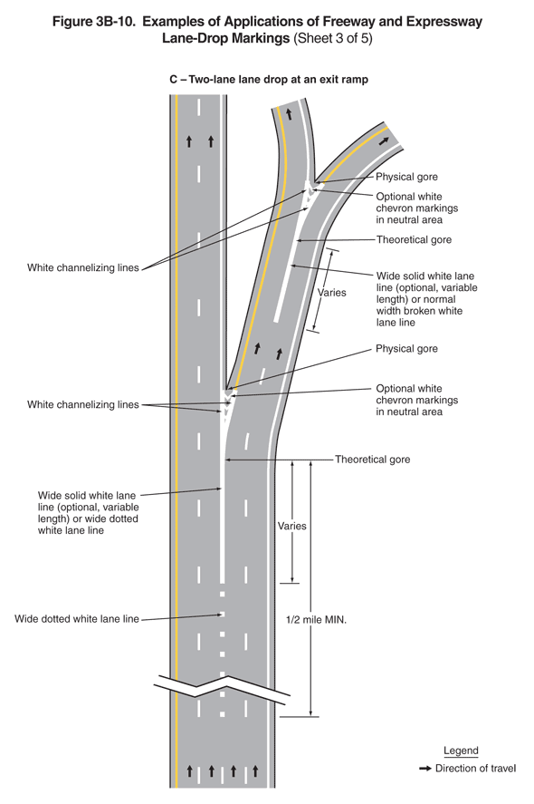
Figure 3B-10. Examples of Applications of Freeway and Expressway Lane-Drop Markings (Sheet 3 of 5)
This figure illustrates five examples of freeway and expressway lane-drop markings. The figure is composed of five sheets.
Sheet 3 shows a figure labeled "C – Two-lane lane drop at an exit ramp." A legend shows a black arrow indicating the direction of travel in the lanes.
The figure shows a vertical highway with four lanes of one direction of a divided highway, two lanes of which continue through past an exit ramp. The two rightmost lanes angle off to the right to become an exit ramp. Arrows indicate that the direction of travel is from the bottom of the figure to the top. A solid yellow line is shown to the left of the leftmost through lane, a solid white line is shown to the right of the rightmost travel lane, and the through lanes are shown separated from each other by a broken white line.
Near the bottom of the figure, the two rightmost lanes are shown becoming the deceleration lanes, leading to a right exit ramp. The deceleration lanes are shown separated from the rightmost of the two remaining through lanes by a wide dotted white lane line. It is shown changing to a solid white line in advance of the theoretical gore. It is labeled as a "wide solid white lane line (optional, variable length) or wide dotted white lane line." The distance from the beginning of the dotted white lane line to the theoretical gore is shown as a dimension of 1/2 mile MIN, and the distance from the beginning of the solid white lane line to the theoretical gore is shown as a dimension that varies. The exit lane is wide enough that the broken white line is shown separating left and right exit lanes. On the left side of the left exit lane, the white lane line joins the white edge line from the right through lane to become white channelizing lines that then form a white triangle or neutral area in front of the physical gore. This triangle is shown with "optional white chevron markings in the neutral area."
The exit ramp angles away to the right, and the broken white line between the two lanes is shown changing to a solid white line in advance of a theoretical gore where the two lanes separate and curve away, one to the left and one to the right. The solid white line is labeled as a "wide solid white lane line (optional, variable length) or normal width broken white lane line." The distance from the beginning of the solid white lane line to the theoretical gore is shown as a dimension that varies. The solid white lane line splits into two white channelizing lines that then form a white triangle or neutral area in front of the physical gore between the two exit lanes. This triangle is shown with "optional white chevron markings in the neutral area." Arrows indicate the direction of travel on the exit lanes.
