2009 Edition Part 3 Figure 3B-14. Examples of Applications of Lane-Reduction Transition Markings

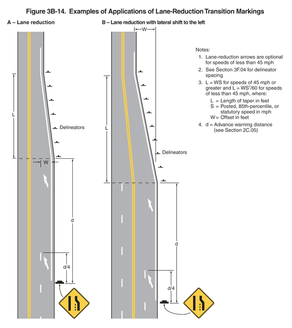
Figure 3B-14. Examples of Applications of Lane-Reduction Transition Markings
This figure illustrates two examples of lane-reduction transition markings.
The figure shows two vertical roadways, examples A and B.
Notes state:
- Lane-reduction arrows are optional for speeds of less than 45 mph
- See Section 3F.04 for delineator spacing
- L = WS for speeds of 45 mph or greater and L = WS2/60 for speeds of less than 45 mph where: L = Length of taper in feet, S = Posted, 85th-percentile or statutory speed in mph, W = Offset in feet.
- d = Advance warning distance (see Section 2C.05).
For both examples, the distance L is shown as the length of the taper from two lanes to one in the northbound direction. The distance W is shown as the width of the lane that is eliminated via the northbound taper. The distance d is shown as the distance from the lane reduction warning sign to the start of the taper from two lanes to one in the northbound direction. The lane reduction sign is shown as a diamond-shaped yellow sign with a black border and legend. It shows a thick, vertical straight line on the left; a thick, vertical line on the right that angles toward the left half way up; and a thin, short vertical dotted line between them that is the length of the vertical section of the line on the right. The north end of last broken white line between the two lanes is shown as a distance of 1/4 of the distance from the lane reduction warning sign to the start of the taper.
- Example A, lane reduction, shows a roadway that reduces from three lanes to two lanes. The figure shows a roadway with one lane traveling south and two lanes (reducing to one lane) traveling north. The lanes in opposing directions are shown separated by a solid double yellow line. The two northbound lanes are shown separated from each other by a broken white line. Two northbound lanes are shown beginning at the bottom of the figure and then reducing to one lane farther north. A solid white line is shown on the outside edge of the northbound pavement, starting at the lane reduction warning sign and ending beyond the end of the lane reduction taper. A diagonal white arrow pointing up and to the left is shown on the pavement between the lane reduction warning sign and the end of the broken white lane line. Another arrow is shown farther north in advance of the taper. Delineators are shown next to the right side of the roadway in the northbound direction along the lane reduction taper.
- Example B, lane reduction with lateral shift to the left, shows a vertical roadway that reduces from four lanes to two lanes. The figure shows a roadway with one lane (increasing to two lanes) in the southbound direction and two lanes (reducing to one lane) in the northbound direction. The lanes in opposing directions are shown separated by a solid double yellow line. The lanes in the same direction are shown separated from each other by a broken white line. One southbound lane is shown beginning at the top of the figure and increasing to two. The solid double yellow line is shown changing from straight to slightly diagonal to the east to accommodate the second southbound lane. Two northbound lanes are shown beginning at the bottom of the figure and then reducing to one lane farther north. A solid white line is shown on the outside edge of the northbound pavement, starting at the lane reduction warning sign and ending beyond the end of the lane reduction taper. A diagonal white arrow pointing up and to the left is shown on the pavement between the lane reduction warning sign and the end of the broken white lane line. Another arrow is shown farther north in advance of the taper. Delineators are shown next to the right side of the roadway in the northbound direction along the lane reduction taper.
