2009 Edition Part 3 Figure 3D-1. Markings for Barrier-Separated Preferential Lanes

Figure 3D-1. Markings for Barrier-Separated Preferential Lanes
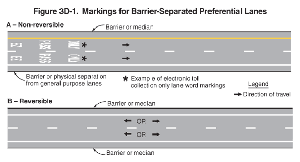
This figure illustrates two examples of markings for barrier-separated preferential lanes.
Two horizontal roadways are shown, A and B. A legend shows a black arrow indicating the direction of travel in the lanes.
- Figure A, non-reversible, shows a two-lane roadway. A solid yellow line separates the left travel lane from a shoulder, a solid white line separates the right travel lane from a shoulder, and a broken white line separates the two lanes from each other. The left shoulder is bordered on the outside by a line labeled "barrier or median," and the right shoulder is bordered on the outside by a line labeled "barrier or physical separation from general purpose lanes." Arrows indicate that the direction of travel is from the left of the figure to the right. In each lane, words are shown marked on the pavement in white on three lines, progressing in the direction of travel from the word "EZ" to the word "PASS" followed by the word "ONLY." These words are noted as an "example of electronic toll collection only lane word markings."
- Figure B, reversible, shows a two-lane roadway. A solid white line is shown on the outside of each lane, separating each from a shoulder. Each shoulder is bordered on the outside by a line labeled "barrier or median." Each lane is shown with a left-facing black arrow, the word "OR," and a right-facing black arrow, denoting travel in either direction.
