
2009 Edition Part 4 Figure 4D-17. Typical Position and Arrangements of Separate Signal Faces for Protected Only Mode Right Turns
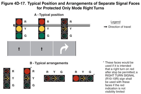
Figure 4D-17. Typical Position and Arrangements of Separate Signal Faces for Protected Only Mode Right Turns
This figure shows the typical position and arrangements of separate signal faces for protected only mode right turns. A legend shows a black arrow indicating the direction of travel on the roadway.
The figure shows two types of examples. The first example is labeled "A – Typical Position." It shows three signals aligned horizontally on a horizontal pole over a vertical segment of three lanes of a roadway. An upward-pointing black arrow is shown in the left and middle lanes denoting the direction of travel as straight through, and a white right-turn arrow is shown marked in the right lane. The left signal is shown above the left lane as a vertical arrangement of circular red, circular yellow, and circular green signal indications. The middle signal is shown above the center lane as a vertical arrangement of circular red, circular yellow, and circular green signal indications. The right signal is shown above the right-turn lane as a vertical arrangement of right-turn red arrow, right-turn yellow arrow, and right-turn green arrow signal indications.
The second type of example is labeled "B – Typical Arrangements." It shows four arrangements. The first arrangement shows a vertical arrangement of three signal indications – right-turn red arrow, right-turn yellow arrow, and right-turn green arrow. The second arrangement shows a vertical arrangement of the same three signal indications except a circular red signal indication is shown instead of a right-turn red arrow, with a note indicating that this face "would be used if it is intended that a right turn on red after stop be permitted; a RIGHT TURN SIGNAL (R10-10R) sign shall be used with this face if the red indication is not visibility limited." The third arrangement shows a horizontal arrangement of the three signal indications shown in the first arrangement. The fourth arrangement shows a horizontal arrangement of the three signal indications shown in the second arrangement, with a note indicating that this face "would be used if it is intended that a right turn on red after stop be permitted; a RIGHT TURN SIGNAL (R10-10R) sign shall be used with this face if the red indication is not visibility limited."