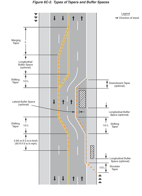
Figure 6C-2. Types of Tapers and Buffer Spaces
This figure illustrates types of tapers and buffer spaces.
The figures shows a vertical divided highway with two lanes in each direction. A legend shows a black arrow indicating the direction of travel on the roadway lanes. Black arrows denoting the direction of travel are shown in the right lanes pointing upward and in the left lanes pointing downward. A double yellow line is shown separating the opposing lanes. A broken white line is shown separating lanes in the same direction. A shoulder is shown to the right of each right lane. Each shoulder is shown with a solid white edge line pavement marking separating the shoulder from the right lane in each direction for the length of the figure.
At the bottom of the figure, to the right of the shoulder, three upside-down T-shaped symbols denoting signs are shown, placed one behind the other. Beyond these symbols, there is an area labeled "Shoulder Taper." The length of the shoulder taper is shown as a dimension of 1/3 L. In this area, beginning at the far right edge of the shoulder, a series of equally spaced orange squares, denoting channelizing devices, taper in to the white line separating the shoulder from the right lane.
Directly above the shoulder taper, traveling upward, an area labeled "Longitudinal Buffer Space (optional)" is shown, in advance of a rectangular area with diagonal lines within the rectangle, denoting a work space, on the right shoulder. Along the right edge of the right lane, the equally spaced orange squares continue from the shoulder taper, and the solid white line separating the shoulder from the lane shifts to the left so that it is to the left of the equally spaced orange squares. Across from the work space, equally spaced orange squares are shown in a straight line along the double yellow line between the opposing lanes. The orange squares continue straight past the work space for a distance shown as a dimension of 0.8S m if S is in km/h (4S ft if S is in mph).
Directly above this area traveling upward, an area labeled "Shifting Taper" is shown as a dimension of ½ L. In this area, the equally spaced orange squares and the solid white line separating the shoulder from the lane are drawn diagonally from the right edge of the roadway across the entire right lane to the broken white separating the right and left lanes. The equally spaced orange squares and the double yellow line between the opposing lanes also are drawn diagonally across the left-hand opposing lane.
Directly above the shifting taper traveling upward, another area labeled "Longitudinal Buffer Space (optional)" is shown in advance of a rectangular are with diagonal lines within the right lane, denoting a work space. The portion of the closed right lane that is to the left of the work space and to the right of the edge line pavement marking is label "Lateral Buffer Space (optional)." For the length of the buffer space and the work space, the equally spaced orange squares and the solid white line continue straight.
Just beyond the work space in the closed right lane, an area is shown labeled "Downstream Taper (optional)." Within this area, a solid white edge line is shown drawn diagonally from the line dividing the left and right lanes to the left edge of the shoulder. Also, equally spaced orange squares are shown directly to the right of and parallel to the diagonal solid white edge line. For the length of this taper, the two northbound lanes shift back to the right, and the solid white line between the left and right lanes is replaced with a broken white line. Along the double yellow line separating the opposing lanes, the double yellow line continues straight and another double yellow line is shown, which is shown shifting to the right with equally spaced orange squares in an area labeled "Shifting Taper" for a dimension shown as ½ L.
Directly above the shifting taper traveling upward, an area is shown labeled "Longitudinal Buffer Space (optional)." In this area, the solid white line separating the shoulder from the northbound right lane is shown to continue straight through the area. The broken white line separating the northbound left and right lanes is also shown to continue straight through the area, as well as the double yellow line separating the opposing lanes. In the southbound lanes, equally spaced orange squares are shown along the double yellow line separating the left and right lanes.
Directly above the longitudinal buffer space traveling upward, an area is shown labeled "Merging Taper," shown as a dimension of "L." In this area, the solid white line separating the shoulder from the northbound right lane is shown to continue straight through the area to the top of the figure. The broken white line separating the northbound left and right lanes is also shown to continue straight the area to the top of the figure, as well as the double yellow line separating the opposing lanes. In the southbound lanes, the double yellow line separating the left and right southbound lanes is drawn diagonally to the double yellow lines separating the opposing lanes. Equally spaced orange squares are shown along this line.
Directly above the merging taper traveling upward, an arrow is shown in each northbound lane pointing upward denoting the direction of travel. An arrow is shown in each southbound lane pointing downward denoting the direction of travel. To the right of the right-hand southbound lane, three upside-down T-shaped symbols denoting signs are shown, placed one behind the other.
