
Figure 6H-31. Lane Closures on Street with Uneven Directional Volumes (TA-31)
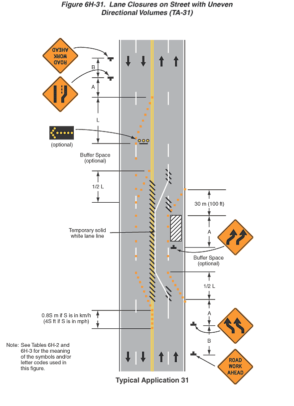
This figure illustrates an example of lane closures on a street with uneven directional volumes. A legend under the figure states that this is Typical Application 31. A note states "Note: See Tables 6H-2 and 6H-3 for the meaning of the symbols and/or letter codes used in this figure."
This figure shows a vertical four-lane roadway with two lanes of traffic in each direction. Downward-pointing black arrows in the two left lanes and upward-pointing arrows in the two right lanes denote the direction of traffic. The opposing lanes are shown separated by a solid double yellow line. The shoulders are shown separated from the right lanes by a solid white line. The two lanes in each direction are shown separated from each other by a broken white lane.
At the bottom of the figure and to the right of the right, northbound lane, a black inverted "T" is shown denoting a sign. The sign is shown as a diamond-shaped orange sign with a black border and the words "ROAD WORK AHEAD" in black. Beyond the sign, at a dimensioned distance B, another sign is shown to the right of the roadway. It is shown as a diamond-shaped orange sign with a black border and two vertical black arrows curving to the left and then straightening vertically, denoting a double lane-shift. Beyond this sign, at a dimensioned distance A, a series of orange squares is shown, denoting channelizing devices, beginning along the solid white line at the right edge of the roadway. The devices are shown tapering diagonally to the left at a dimensioned distance ½ L to the broken white line dividing the two northbound lanes. The devices then are shown continuing along the broken white line dividing the two northbound lanes through a buffer space labeled optional. At the end of the buffer space, another double lane-shift sign is shown in advance of a vertical rectangle with diagonal black and white stripes, denoting a work space. The sign and work space are shown as a dimensioned distance A. The channelizing devices are shown continuing along the broken white line to the left of the work space. Beyond the work space, for a dimensioned distance of 30 m (100 ft), the channelizing devices are shown tapering to the right to the solid white edge line.
At the point where the channelizing devices are first shown beginning to taper to the left, diagonal black lines are shown obscuring the broken white line between the two northbound lanes. Beginning at this point on the broken white line, a white line denoted as a temporary solid white line is shown tapering to the left to the solid double yellow line and running parallel to the channelizing devices at the same dimensioned distance ½ L. The temporary solid white line then is shown continuing to the right of the solid double yellow line beyond the work space and then tapering to the right, paralleling the channelizing devices, at a dimensioned distance of 30 m (100 ft), where it is shown joining the broken white line between the two northbound lanes. Diagonal black lines are shown obscuring the broken white line where the solid white line joins it.
At the point where the channelizing devices and the temporary solid white line are shown beginning to taper to the left, a series of diagonal black lines is shown obscuring the solid double yellow line between the northbound and southbound lanes. These diagonal lines are shown continuing through the work space and ending where the temporary solid white line joins the broken white line between the northbound lanes.
At the top of the figure and outside the right, southbound lane, a black inverted "T" is shown denoting a sign. It is shown as a Road Work Ahead sign. Beyond the sign, at a dimensioned distance B, another sign is shown to the right of the roadway. It shows a thick, vertical straight line on the right; a thick, vertical line on the left that angles toward the right half way up; and a thin, short vertical dotted line between them that is the length of the vertical section of the line on the left, denoting a lane ends. Beyond this sign, at a dimensioned distance A, a series of orange squares is shown, denoting channelizing devices, beginning along the solid double yellow line dividing the opposing lanes. The devices are shown tapering diagonally to the right at a dimensioned distance L to the broken white line shown dividing the two southbound lanes. At this point, a horizontal rectangular black arrow panel with a yellow directional arrow pointing to the shoulder is shown in the left-hand southbound lane and labeled optional. The channelizing devices then are shown continuing along the broken white line dividing the two southbound lanes through a buffer space labeled optional. At the end of the buffer space, the channelizing devices are shown continuing along the broken white line and another series of devices is shown beginning on the solid double yellow line and tapering to the right for a dimensioned distance ½ L where they are shown joining the broken white line. The channelizing devices are shown continuing along the broken white line beyond the work space and the buffer space south of the work space and then tapering to the left for a dimensioned distance ½ L to the solid double yellow line. They are shown continuing along the solid double yellow line for a dimensioned distance of 0.8 m if S is in km/h (4S ft if S is in mph).