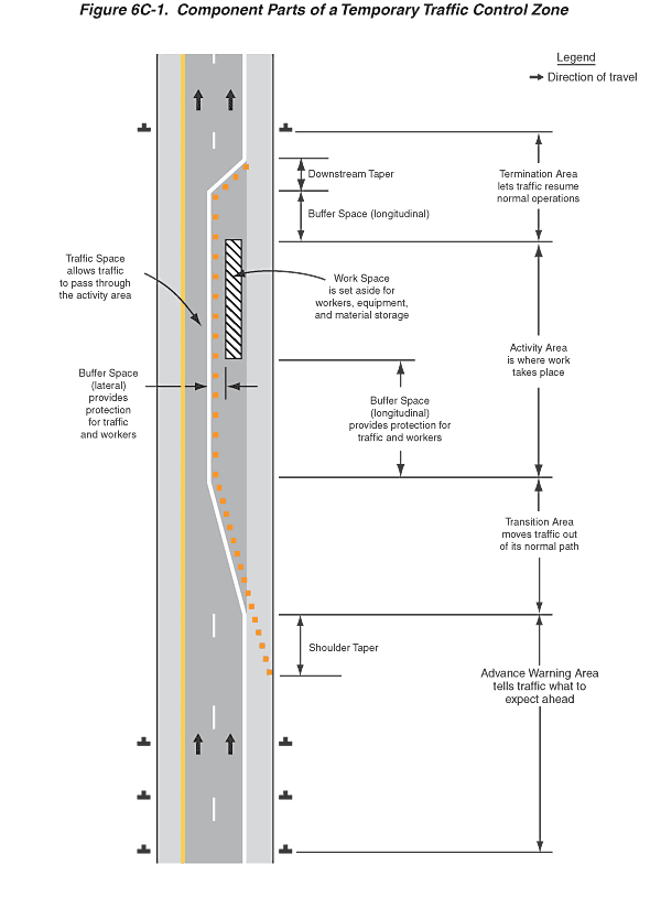
Figure 6C-1. Component Parts of a Temporary Traffic Control Zone
This figure illustrates component parts of a temporary traffic control zone.
The figure shows one direction of a divided highway with two lanes adjacent to each other traveling in an upward direction. A legend shows a black arrow indicating the direction of travel on the roadway lanes. Arrows denoting direction of travel are shown in each lane pointing upward. There are left and right shoulders shown outside of the two lanes. The left shoulder is shown with a solid yellow edge line pavement marking that runs the full length of the figure separating the left shoulder from the left lane. The right shoulder is shown with a solid white edge line pavement marking separating the right shoulder from the right lane that runs from the bottom of the figure to the end of the section of road that is labeled "Advance Warning Area." At the end of the "Advance Warning Area," the right lane and right shoulder are shown as closed and shown as reopened beyond the end of the section of road that is labeled "Downstream Taper." Four component parts of a temporary traffic control zone are illustrated on the right side of this figure, which are described as follows:
- At the bottom of the figure, the first component part of a temporary traffic control zone is labeled the "Advance Warning Area tells traffic what to expect ahead." This area is illustrated with solid white line edge pavement markings along the right edge of the roadway, which separates the right shoulder from the right edge of roadway. Along the center of the roadway, a broken white line is shown that runs the full length of the advance warning area separating the two lanes of traffic. Also within this area, a solid yellow line edge is shown along the left edge of the roadway, which separates the left shoulder from the left edge of the roadway. Three symbols in the shape of an upside-down letter "T" representing a sign location are shown along the right side of the road equally spaced apart in the advance warning area. The upper portion of the advance warning area is shown as an area labeled "Shoulder Taper." Within this area, a series of equally spaced orange squares are shown that run diagonally from the right edge of the shoulder to the left edge of the shoulder.
- Directly above the advance warning area traveling upward, the next component part of the temporary traffic control zone is shown, labeled the "Transition Area moves traffic out of its normal path." In this area along the roadway, a solid white edge line is drawn diagonally from the right edge of the roadway to the center of the roadway. Also, a series of equally spaced orange squares are shown, representing channelizing devices, that run parallel to and to the right of the solid white diagonal edge line noted above.
- Directly above the transition area traveling upward, the next component part of the temporary traffic control zone is shown, labeled the "Activity Area is where work takes place." The activity area is shown divided into two successive spaces, the lower of which is labeled the "Buffer Space (longitudinal) provides protection for traffic and workers." Directly above the buffer space (longitudinal) traveling upward, a space is shown labeled "Work Space is set aside for workers, equipment, and material storage." This space is illustrated as being within the closed right lane and is shown as a rectangular area with diagonal lines within the rectangle. Throughout the activity area, the open lane of traffic is labeled "Traffic Space allows traffic to pass through the activity area." Also throughout the activity area, the portion of the closed right lane that is to the right of the edge line pavement marking and to the left of the work space is labeled "Buffer Space (lateral) provides protection for traffic and workers." Throughout the activity area, to the right of and parallel to the solid white edge line pavement markings, a series of equally spaced orange squares are shown.
- Directly above the activity area traveling upward, the next component part of the temporary traffic control zone is shown labeled "Termination Area lets traffic resume normal operations." The termination area is divided into three successive spaces; the lower space is labeled "Buffer Space (longitudinal)." Within the buffer space (longitudinal), a solid white edge line is shown along the center of the roadway, and parallel to and to the right of the solid white edge line, a series of equally spaced orange squares are shown. Directly above the buffer space (longitudinal) traveling upward in the middle area of the termination area, a space is shown labeled "Downstream Taper." Within the downstream taper, a solid white edge line is shown drawn diagonally from the center of the roadway to the left edge of the shoulder. Also, equally spaced orange squares are shown directly to the right of and parallel to the diagonal solid white edge line. Directly above the downstream taper area, the solid white edge line is shown to continue upward to the end of the area labeled "Termination Area" and beyond, to the end of the figure, separating the right edge of the pavement from the left edge of the shoulder. A symbol in the shape of an upside-down letter "T," representing a sign location, is shown on the left and right sides of the road, at the upper end of the termination area. Directly above the downstream taper area in the roadway, an arrow is shown in each lane pointing upward denoting the direction of travel. Also, in the center of the roadway above the downstream taper area, a broken white line is shown separating the two lanes of traffic.
