
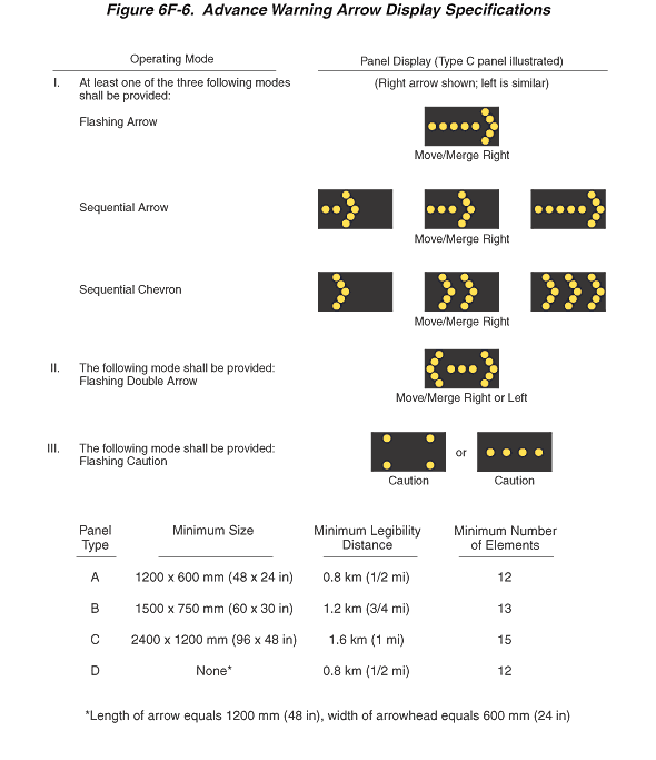
Figure 6F-6. Advance Warning Arrow Display Specifications
This figure illustrates advance warning arrow display specifications.
On the left side of the page is the heading "Operating Mode". Three operating modes are shown, with the representative advance warning arrow panel displays shown as yellow dots on a horizontal rectangular black background on the right side of the page under the heading "Panel Display (Type C panel illustrated)." Below the above heading on the right side of the page is the notation "(Right arrow shown; left is similar)."
Under "Operating Mode," the first heading is "I. At least one of the three following modes shall be provided:" Under that heading, the following listings are shown under "Operating Mode," with accompanying illustration and text under "Panel Display":
- "Flashing Arrow": A panel display is shown of a horizontal arrow pointing to the right, with a shaft composed of five yellow dots leading to an arrowhead composed of five yellow dots. A note under the panel display illustration states: "Move/Merge Right."
- "Sequential Arrow": Three separate illustrations of panel displays are shown, each displaying a horizontal arrow pointing to the right, with an arrowhead composed of five yellow dots. The shafts of the arrows in the three separate illustrations are composed of two, three, and five yellow dots, respectively. In each of the three illustrations, the left-most yellow dot of the arrow shaft is located near the left edge of the panel and the arrowhead is just to the right of the right-most dot of the shaft. A note under the panel display illustrations states: "Move/Merge Right."
- "Sequential Chevron": Three separate illustrations of panel displays are shown, each displaying one or more chevron arrows pointing to the right, with each chevron arrow composed of five yellow dots. In the first of the three illustrations, one chevron arrow is shown, located at the left side of the panel. In the second illustration, two chevron arrows are shown, located at the left and center portions of the panel. In the third illustration, three chevron arrows are shown, located at the left, center, and right portions of the panel. A note under the panel display illustrations states: "Move/Merge Right."
Under "Operating Mode," the second heading is: "II: The following mode shall be provided: Flashing Double Arrow." Under the heading "Panel Display," a double-headed horizontal arrow is shown composed of three yellow dots in a horizontal line with each arrowhead composed of five yellow lights. A note under the panel display illustration states: "Move/Merge Right or Left."
Under "Operating Mode," the third heading is: "III. The following mode shall be provided: Flashing Caution." Under the heading "Panel Display," two separate illustrations are shown, separated by the word "or." One illustration shows four yellow dots, one near each of the four corners of the display panel. The second illustration shows a horizontal row of four yellow dots. A note stating "Caution" is shown under each of the two illustrations.
A table shows the following—minimum size, minimum legibility distance, and minimum number of elements—for the four panel types:
- Panel type A: minimum size 1200 x 600 mm (48 x 24 in), minimum legibility distance 0.8 km (1/2 mi), and minimum 12 elements.
- Panel type B: minimum size 1500 x 750 mm (60 x 30 in), minimum legibility distance 1.2 km (3/4 mi), and minimum 13 elements.
- Panel type C: minimum size 2400 x 1200 mm (96 x 48 in), minimum legibility distance 1.6 km (1 mi), and minimum 15 elements.
- Panel type D: minimum size "None*", minimum legibility distance 0.8 km (1/2 mi), and minimum 12 elements. A note states that asterisk (*) indicates "length of arrow equals 1200 mm (48 in), width of arrowhead equals 600 mm (24 in)."