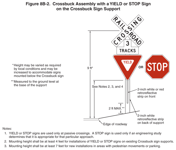
2009 Edition Part 8 Figure 8B-2. Crossbuck Assembly with a YIELD or STOP Sign on the Crossbuck Sign Support

Figure 8B-2. Crossbuck Assembly with a YIELD or STOP Sign on the Crossbuck Sign Support
This figure shows an example of how a YIELD or STOP sign is mounted on a Crossbuck sign support.
The example shows an R15-1 Crossbuck sign with the words "RAILROAD CROSSING" mounted above an R15-2 sign with the words "3 TRACKS." These two signs are shown mounted together on a sign support above either a YIELD sign or a STOP sign. A note states: "YIELD or STOP signs are used only at passive crossings. A STOP sign is used only if an engineering study determines that it is appropriate for that particular approach."
A white or red retroreflective strip shown as a dimension of 2 inches wide is shown attached on the front of the sign support a dimensioned distance of 2 ft MAX measured to the ground level at the base of the support. A white retroreflective strip shown as a dimension of 2 inches wide is shown attached on the back of the support.
The center of the crossbuck is shown at a dimensioned distance of 9 ft above the roadway level. A note states: "Height may be varied as required by local conditions and may be increased to accommodate signs mounted below the Crossbuck sign."
The distance from the bottom of the YIELD or STOP sign to the roadway level is noted as follows:
- "Mounting height shall be at least 4 feet for installations of YIELD or STOP signs on existing Crossbuck sign supports.
- Mounting height shall be at least 5 feet for new installations."
