2009 Edition Part 8 Figure 8B-8. Example of Dynamic Envelope Pavement Markings at Grade Crossings

Figure 8B-8. Example of Dynamic Envelope Pavement Markings at Grade Crossings
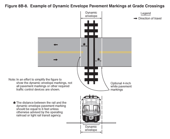
This figure shows two examples: one of dynamic envelope pavement markings and one of a dynamic envelope.
The first figure shows a horizontal two-lane roadway. Double yellow lines separate the two lanes. A legend shows that a black arrow indicates the direction of travel. Black arrows on the roadway show the direction of travel as one lane in each direction.
A note states: "In an effort to simplify the figure to show the dynamic envelope markings, not all pavement markings or other required traffic control devices are shown."
In the center of the figure, a symbol of a vertical railroad track is shown across the roadway. The train dynamic envelope is indicated as an area extending on both sides of the track for an undimensioned distance. Vertical white pavement markings that are parallel to the track are shown extending across the roadway at the edges of the dynamic envelope. The markings are shown as optional 4-inch white pavement markings. The distance from the edge of the pavement marking to the outside edge of the railroad track is noted as: "The distance between the rail and the dynamic envelope pavement marking should be equal to 6 feet unless otherwise advised by the operating railroad or light rail transit agency."
The second figure illustrates the clearance required for the train and its cargo overhang due to any combination of loading, lateral motion, or suspension failure. A head-on drawing of a train engine is shown. Vertical lines drawn from the top of the roof beyond the wheels on the track define the dynamic envelope.
