
Chapter 6F. Temporary Traffic Control Zone Devices
Section 6F.56 Arrow Panels
Standard:
An arrow panel shall be a sign with a matrix of elements capable
of either flashing or sequential displays. This sign shall provide
additional warning and directional information to assist in merging
and controlling road users through or around a TTC zone.
Guidance:
An arrow panel in the arrow or chevron mode should be used to advise
approaching traffic of a lane closure along major multi-lane roadways
in situations involving heavy traffic volumes, high speeds, and/or
limited sight distances, or at other locations and under other conditions
where road users are less likely to expect such lane closures.
If used, an arrow panel should be used in combination with appropriate signs, channelizing devices, or other TTC devices.
An arrow panel should be placed on the shoulder of the roadway or, if practical, further from the traveled lane. It should be delineated with retroreflective TTC devices. When an arrow panel is not being used, it should be removed; if not removed, it should be shielded; or if the previous two options are not feasible, it should be delineated with retroreflective TTC devices.
Standard:
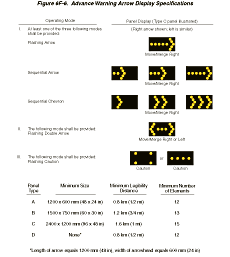
Arrow panels shall meet the minimum size, legibility distance, number
of elements, and other specifications shown on Figure 6F-6.
Figure 6F-6 Advance Warning Arrow Display Specifications
Support:
Type A arrow panels are appropriate for use on low-speed urban streets.
Type B arrow panels are appropriate for intermediate-speed facilities
and for maintenance or mobile operations on high-speed roadways.
Type C arrow panels are intended to be used on high-speed, high-volume
motor vehicle traffic control projects. Type D arrow panels are
intended for use on authorized vehicles.
Standard:
Type A, B, and C arrow panels shall have solid rectangular appearances.
A Type D arrow panel shall conform to the shape of the arrow.
All arrow panels shall be finished in nonreflective black. The arrow panel shall be mounted on a vehicle, a trailer, or other suitable support.
Guidance:
The minimum mounting height of an arrow panel should be 2.1 m (7
ft) from the roadway to the bottom of the panel, except on vehicle-mounted
panels, which should be as high as practical.
A vehicle-mounted arrow panel should be provided with remote controls.
Standard:
Arrow panel elements shall be capable of at least a 50 percent dimming
from full brilliance. The dimmed mode shall be used for nighttime
operation of arrow panels.
Guidance:
Full brilliance should be used for daytime operation of arrow panels.
Standard:
The arrow panel shall have suitable elements capable of the various
operating modes. The color presented by the elements shall be yellow.
Guidance:
If an arrow panel consisting of a bulb matrix is used, the elements
should be recess-mounted or equipped with an upper hood of not less
than 180 degrees.
Standard:
The minimum element on-time shall be 50 percent for the flashing
mode, with equal intervals of 25 percent for each sequential phase.
The flashing rate shall be not less than 25 nor more than 40 flashes
per minute.
An arrow panel shall have the following three mode selections:
- A Flashing Arrow, Sequential Arrow, or Sequential Chevron mode; and
- A flashing Double Arrow mode; and
- A flashing Caution mode.
An arrow panel in the arrow or chevron mode shall be used only for stationary or moving lane closures on multi-lane roadways.
For shoulder work, blocking the shoulder, for roadside work near the shoulder, or for temporarily closing one lane on a two-lane, two-way roadway, an arrow panel shall be used only in the caution mode.
Guidance:
For a stationary lane closure, the arrow panel should be located
on the shoulder at the beginning of the merging taper.
Where the shoulder is narrow, the arrow panel should be located in the closed lane.
Standard:
When arrow panels are used to close multiple lanes, a separate arrow
panel shall be used for each closed lane.
Guidance:
When arrow panels are used to close multiple lanes, if the first
arrow panel is placed on the shoulder, the second arrow panel should
be placed in the first closed lane at the beginning of the second
merging taper (see Figure 6H-37).
When the first arrow panel is placed in the first closed lane, the
second arrow panel should be placed in the second closed lane at
the downstream end of the second merging taper.
For mobile operations where a lane is closed, the arrow panel should be located to provide adequate separation from the work operation to allow for appropriate reaction by approaching drivers.
Standard:
A vehicle displaying an arrow panel shall be equipped with high-intensity
rotating, flashing, oscillating, or strobe lights.
Arrow panels shall not be used to laterally shift traffic.
Option:
A portable changeable message sign may be used to simulate an arrow
panel display.
Section 6F.57 High-Level Warning Devices (Flag Trees)
Option:
A high-level warning device (flag tree) may supplement other TTC
devices in TTC zones.
Support:
A high-level warning device is designed to be seen over the top
of typical passenger cars. A typical high-level warning device is
shown in Figure 6F-2.
Standard:
A high-level warning device shall consist of a minimum of two flags
with or without a Type B high-intensity flashing warning light.
The distance from the roadway to the bottom of the lens of the light
and to the lowest point of the flag material shall be not less than
2.4 m (8 ft). The flag shall be 400 mm (16 in) square or larger
and shall be orange or fluorescent red-orange in color.
Option:
An appropriate warning sign may be mounted below the flags.
Support:
High-level warning devices are most commonly used in high-density
road user situations to warn road users of short-term operations.
Section 6F.58 Channelizing Devices
Standard:
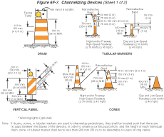
Designs of various channelizing devices shall be as shown in Figure
6F-7.
Figure 6F-7 Channelizing Devices (2 Sheets)
Support:
The function of channelizing devices is to warn road users of conditions
created by work activities in or near the roadway and to guide road
users. Channelizing devices include cones, tubular markers, vertical
panels, drums, barricades, and temporary raised islands.
Channelizing devices provide for smooth and gradual vehicular traffic flow from one lane to another, onto a bypass or detour, or into a narrower traveled way. They are also used to separate vehicular traffic from the work space, pavement drop-offs, pedestrian or shared-use paths, or opposing directions of vehicular traffic.
Standard:
Devices used to channelize pedestrians shall be detectable to users
of long canes and visible to persons having low vision.
Where barricades are used to channelize pedestrians, there shall be continuous detectable bottom and top rails with no gaps between individual barricades to be detectable to users of long canes. The bottom of the bottom rail shall be no higher than 150 mm (6 in) above the ground surface. The top of the top rail shall be no lower than 900 mm (36 in) above the ground surface.
Option:
A gap not exceeding 150 mm (6 in) between the bottom rail and the
ground surface may be used to facilitate drainage.
Standard:
If drums, cones, or tubular markers are used to channelize pedestrians,
they shall be located such that there are no gaps between the bases
of the devices, in order to create a continuous bottom, and the
height of each individual drum, cone, or tubular marker shall be
no less than 900 mm (36 in) to be detectable to users of long canes.
Guidance:
Channelizing devices should be constructed and ballasted to perform
in a predictable manner when inadvertently struck by a vehicle.
Channelizing devices should be crashworthy. Fragments or other debris
from the device or the ballast should not pose a significant hazard
to road users or workers.
The spacing of channelizing devices should not exceed a distance in meters (feet) equal to 0.2 times the speed limit in km/h (1.0 times the speed limit in mph) when used for taper channelization, and a distance in meters (feet) equal to 0.4 times the speed limit in km/h (2.0 times the speed limit in mph) when used for tangent channelization.
When channelizing devices have the potential of leading vehicular traffic out of the intended vehicular traffic space as shown in Figure 6H-39, the channelizing devices should be extended a distance in meters (feet) of 0.4 times the speed limit in km/h (2.0 times the speed limit in mph) beyond the end of the transition area.
Option:
Warning lights may be added to channelizing devices in areas with
frequent fog, snow, or severe roadway curvature, or where visual
distractions are present.
Standard:
Warning lights shall flash when placed on channelizing devices used
alone or in a cluster to warn of a condition. Warning lights placed
on channelizing devices used in a series to channelize road users
shall be steady-burn.
The retroreflective material used on channelizing devices shall have a smooth, sealed outer surface that will display a similar color day or night.
Option:
The name and telephone number of the highway agency, contractor,
or supplier may be shown on the nonretroreflective surface of all
types of channelizing devices.
Standard:
The letters and numbers of the name and telephone number shall be
nonretroreflective and not over 50 mm (2 in) in height.
Guidance:
Particular attention should be given to maintaining the channelizing
devices to keep them clean, visible, and properly positioned at
all times.
Standard:
Devices that are damaged or have lost a significant amount of their
retroreflectivity and effectiveness shall be replaced.
Section 6F.59 Cones
Standard:
Cones (see Figure 6F-7, Sheet
1 of 2) shall be predominantly orange and shall be made of a
material that can be struck without causing damage to the impacting
vehicle. For daytime and low-speed roadways, cones shall be not
less than 450 mm (18 in) in height. When cones are used on freeways
and other high-speed highways or at night on all highways, or when
more conspicuous guidance is needed, cones shall be a minimum of
700 mm (28 in) in height.
For nighttime use, cones shall be retroreflectorized or equipped with lighting devices for maximum visibility. Retroreflectorization of cones that are 700 to 900 mm (28 to 36 in) in height shall be provided by a 150 mm (6 in) wide white band located 75 to 100 mm (3 to 4 in) from the top of the cone and an additional 100 mm (4 in) wide white band located approximately 50 mm (2 in) below the 150 mm (6 in) band.
Retroreflectorization of cones that are more than 900 mm (36 in) in height shall be provided by horizontal, circumferential, alternating orange and white retroreflective stripes that are 100 to 150 mm (4 to 6 in) wide. Each cone shall have a minimum of two orange and two white stripes with the top stripe being orange. Any nonretroreflective spaces between the orange and white stripes shall not exceed 75 mm (3 in) in width.
Option:
Traffic cones may be used to channelize road users, divide opposing
vehicular traffic lanes, divide lanes when two or more lanes are
kept open in the same direction, and delineate short duration maintenance
and utility work.
Guidance:
Steps should be taken to minimize the possibility of cones being
blown over or displaced by wind or moving vehicular traffic.
Cones should not be used for pedestrian channelization or as pedestrian barriers in TTC zones on or along sidewalks unless they are continuous between individual devices and detectable to users of long canes.
Option:
Cones may be doubled up to increase their weight.
Support:
Some cones are constructed with bases that can be filled with ballast.
Others have specially weighted bases, or weight such as sandbag
rings that can be dropped over the cones and onto the base to provide
added stability.
Guidance:
Ballast should be kept to the minimum amount needed.
Section 6F.60 Tubular Markers
Standard:
Tubular markers (see Figure 6F-7, Sheet 1 of 2) shall be predominantly
orange and shall be not less than 450 mm (18 in) high and 50 mm
(2 in) wide facing road users. They shall be made of a material
that can be struck without causing damage to the impacting vehicle.
Tubular markers shall be a minimum of 700 mm (28 in) in height when they are used on freeways and other high-speed highways, on all highways during nighttime, or whenever more conspicuous guidance is needed.
For nighttime use, tubular markers shall be retroreflectorized. Retroreflectorization of 700 mm (28 in) or larger tubular markers shall be provided by two 75 mm (3 in) wide white bands placed a maximum of 50 mm (2 in) from the top with a maximum of 150 mm (6 in) between the bands.
Guidance:
Tubular markers should not be used for pedestrian channelization
or as pedestrian barriers in TTC zones on or along sidewalks unless
they are continuous between individual devices and detectable to
users of long canes.
Tubular markers have less visible area than other devices and should be used only where space restrictions do not allow for the use of other more visible devices.
Tubular markers should be stabilized by affixing them to the pavement, by using weighted bases, or weights such as sandbag rings that can be dropped over the tubular markers and onto the base to provide added stability. Ballast should be kept to the minimum amount needed.
Option:
Tubular markers may be used effectively to divide opposing lanes
of road users, divide vehicular traffic lanes when two or more lanes
of moving motor vehicle traffic are kept open in the same direction,
and to delineate the edge of a pavement drop off where space limitations
do not allow the use of larger devices.
Standard:
When a noncylindrical tubular marker is used, it shall be attached
to the pavement in a manner such that the width facing road users
meets the minimum requirements.
A tubular marker shall be attached to the pavement to display the minimum 50 mm (2 in) width to the approaching road users.
Section 6F.61 Vertical Panels
Standard:
Vertical panels (see Figure 6F-7, Sheet 1 of 2) shall be 200 to
300 mm (8 to 12 in) in width and at least 600 mm (24 in) in height.
They shall have orange and white diagonal stripes and be retroreflectorized.
Vertical panels shall be mounted with the top a minimum of 900 mm (36 in) above the roadway.
Where the height of the vertical panel itself is 900 mm (36 in) or greater, a panel stripe width of 150 mm (6 in) shall be used.
Option:
Where the height of the vertical panel itself is less than 900 mm
(36 in), a panel stripe width of 100 mm (4 in) may be used.
Standard:
Markings for vertical panels shall be alternating orange and white
retroreflective stripes, sloping downward at an angle of 45 degrees
in the direction vehicular traffic is to pass. Vertical panels used
on freeways, expressways, and other high-speed roadways shall have
a minimum of 169,000 mm2 (270 in2) retroreflective
area facing vehicular traffic.
Option:
Where space is limited, vertical panels may be used to channelize
vehicular traffic, divide opposing lanes, or replace barricades.
Section 6F.62 Drums
Standard:
Drums (see Figure 6F-7, Sheet 1 of 2) used for road user warning
or channelization shall be constructed of lightweight, deformable
materials. They shall be a minimum of 900 mm (36 in) in height and
have at least a 450 mm (18 in) minimum width regardless of orientation.
Metal drums shall not be used. The markings on drums shall be horizontal,
circumferential, alternating orange and white retroreflective stripes
100 to 150 mm (4 to 6 in) wide. Each drum shall have a minimum of
two orange and two white stripes with the top stripe being orange.
Any nonretroreflectorized spaces between the horizontal orange and
white stripes shall not exceed 75 mm (3 in) wide. Drums shall have
closed tops that will not allow collection of construction debris
or other debris.
Support:
Drums are highly visible, have good target value, give the appearance
of being formidable obstacles and, therefore, command the respect
of road users. They are portable enough to be shifted from place
to place within a TTC zone in order to accommodate changing conditions,
but are generally used in situations where they will remain in place
for a prolonged period of time.
Option:
Although drums are most commonly used to channelize or delineate
road user flow, they may also be used alone or in groups to mark
specific locations.
Guidance:
Drums should not be used for pedestrian channelization or as pedestrian
barriers in TTC zones on or along sidewalks unless they are continuous
between individual devices and detectable to users of long canes.
Drums should not be weighted with sand, water, or any material to the extent that would make them hazardous to road users or workers when struck. Drums used in regions susceptible to freezing should have drain holes in the bottom so that water will not accumulate and freeze causing a hazard if struck by a road user.
Standard:
Ballast shall not be placed on the top of a drum.
Section 6F.63 Type I, II, or III Barricades
Support:
A barricade is a portable or fixed device having from one to three
rails with appropriate markings and is used to control road users
by closing, restricting, or delineating all or a portion of the
right-of-way.
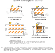
As shown in Figure 6F-7, Sheet 2 of 2, barricades are classified as either Type I, Type II, or Type III.
Standard:
Stripes on barricade rails shall be alternating orange and white
retroreflective stripes sloping downward at an angle of 45 degrees
in the direction road users are to pass. Except as noted in the
Option, the stripes shall be 150 mm (6 in) wide.
Option:
When rail lengths are less than 900 mm (36 in), 100 mm (4 in) wide
stripes may be used.
Standard:
The minimum length for Type I and Type II Barricades shall be 600
mm (24 in), and the minimum length for Type III Barricades shall
be 1200 mm (48 in). Each barricade rail shall be 200 to 300 mm (8
to 12 in) wide. Barricades used on freeways, expressways, and other
high-speed roadways shall have a minimum of 169,000 mm2
(270 in2) of retroreflective area facing road users.
Guidance:
Where barricades extend entirely across a roadway, the stripes should
slope downward in the direction toward which road users must turn.
Where both right and left turns are provided, the barricade stripes should slope downward in both directions from the center of the barricade or barricades.
Where no turns are intended, the stripes should be positioned to slope downward toward the center of the barricade or barricades.
Barricade rails should be supported in a manner that will allow them to be seen by the road user, and in a manner that provides a stable support that is not easily blown over or displaced.
The width of the existing pedestrian facility should be provided for the temporary facility if practical. Traffic control devices and other construction materials and features should not intrude into the usable width of the sidewalk, temporary pathway, or other pedestrian facility. When it is not possible to maintain a minimum width of 1500 mm (60 in) throughout the entire length of the pedestrian pathway, a 1500 x 1500 mm (60 x 60 in) passing space should be provided at least every 60 m (200 ft) to allow individuals in wheelchairs to pass.
Barricade rail supports should not project into pedestrian circulation routes more than 100 mm (4 in) from the support between 675 mm (27 in) and 2000 mm (80 in) from the surface as described in Section 4.4.1 of the "Americans with Disabilities Act Accessibility Guidelines for Buildings and Facilities (ADAAG) (see Section 1A.11).
Option:
For Type I Barricades, the support may include other unstriped horizontal
panels necessary to provide stability.
Guidance:
Barricades should be crashworthy as they are located adjacent to
vehicular traffic flow and are subject to impact by errant vehicles.
On high-speed expressways or in other situations where barricades may be susceptible to overturning in the wind, ballasting should be used.
Option:
Sandbags may be placed on the lower parts of the frame or the stays
of barricades to provide the required ballast.
Standard:
Ballast shall not be placed on top of any striped rail. Barricades
shall not be ballasted by nondeformable objects such as rocks or
chunks of concrete. Ballast shall not extend into the accessible
passage width of 1500 mm (60 in).
Support:
Type I or Type II Barricades are intended for use in situations
where road user flow is maintained through the TTC zone.
Option:
Barricades may be used alone or in groups to mark a specific condition
or they may be used in a series for channelizing road users.
Type I Barricades may be used on conventional roads or urban streets.
Guidance:
Type II or Type III Barricades should be used on freeways and expressways
or other high-speed roadways. Type III Barricades should be used
to close or partially close a road.
Option:
Type III Barricades used at a road closure may be placed completely
across a roadway or from curb to curb.
Guidance:
Where provision is made for access of authorized equipment and vehicles,
the responsibility for Type III Barricades should be assigned to
a person who will provide proper closure at the end of each work
day.
Support:
When a highway is legally closed but access must still be allowed
for local road users, barricades usually are not extended completely
across the roadway.
Standard:
A sign (see Section 6F.09)
shall be installed with the appropriate legend concerning permissible
use by local road users. Adequate visibility of the barricades from
both directions shall be provided.
Option:
Signs may be installed on barricades (see Section
6F.03).
Section 6F.64 Direction Indicator Barricades
Standard:
The Direction Indicator Barricade (see Figure 6F-7, Sheet 2 of 2)
shall consist of a One-Direction Large Arrow (W1-6) sign mounted
above a diagonal, striped, horizontally aligned, retroreflective
rail.
The One-Direction Large Arrow (W1-6) sign shall be black on an orange background. The stripes on the bottom rail shall be alternating orange and white retroreflective stripes sloping downward at an angle of 45 degrees in the direction road users are to pass. The stripes shall be 100 mm (4 in) wide. The One-Direction Large Arrow (W1-6) sign shall be 600 x 300 mm (24 x 12 in). The bottom rail shall have a length of 600 mm (24 in) and a height of 200 mm (8 in).
Guidance:
The Direction Indicator Barricade, including any associated ballast
or lights, should be crashworthy.
Option:
The Direction Indicator Barricade may be used in tapers, transitions,
and other areas where specific directional guidance to drivers is
necessary.
Guidance:
If used, Direction Indicator Barricades should be used in series
to direct the driver through the transition and into the intended
travel lane.
Section 6F.65 Temporary Traffic Barriers as Channelizing Devices
Support:
Temporary traffic barriers are not TTC devices in themselves; however,
when placed in a position identical to a line of channelizing devices
and marked and/or equipped with appropriate channelization features
to provide guidance and warning both day and night, they serve as
TTC devices.
Standard:
Temporary traffic barriers serving as TTC devices shall conform
to requirements for such devices as set forth throughout Part 6.
Temporary traffic barriers shall not be used solely to channelize road users, but also to protect the work space (see Section 6F.81). If used to channelize vehicular traffic, the temporary traffic barrier shall be supplemented with delineation, pavement markings, or channelizing devices for improved daytime and nighttime visibility.
Guidance:
Temporary traffic barriers should not be used for a merging taper
except in low-speed urban areas. Temporary traffic barriers should
not be used for a constricted/restricted TTC zone.
When it is necessary to use a temporary traffic barrier for a merging taper in low-speed urban areas or for a constricted/restricted TTC zone, the taper shall be delineated and the taper length should be designed to optimize road user operations considering the available geometric conditions.
When used for channelization, temporary traffic barriers should be of a light color for increased visibility.
Section 6F.66 Longitudinal Channelizing Barricades
Support:
Longitudinal channelizing barricades are lightweight, deformable
channelizing devices that can be used singly as Type I, II, or III
barricades, or connected so they are highly visible and have good
target value.
Guidance:
When used as a barricade, longitudinal channelizing barricades should
conform to the general size, color, stripe pattern, retroreflectivity,
and placement characteristics established for the devices described
in Chapter 6F.
Option:
Longitudinal channelizing barricades may be used instead of a line
of cones, drums, or barricades.
Longitudinal channelizing barricades may be hollow and filled with water as a ballast.
Guidance:
If used, longitudinal channelizing barricades should be interlocked
to delineate or channelize flow including pedestrian traffic control.
The interlocking barricade wall should not have gaps that allow
pedestrians or vehicles to stray from the channelizing path.
Support:
Longitudinal channelizing barricades are often located adjacent
to traffic and therefore are subject to impact by errant vehicles.
Guidance:
Because of their vulnerable position, longitudinal channelizing
barricades should be constructed of lightweight materials and be
crashworthy.
Although longitudinal channelizing barricades might give the appearance of being formidable obstacles, they have not met the crashworthy requirements for temporary traffic barriers and, therefore, should not be used to shield pedestrians, including workers, from vehicle impacts or obstacles.
Option:
Longitudinal channelizing barricades may be used to channelize pedestrians.
Section 6F.67 Other Channelizing Devices
Option:
Channelizing devices other than those described in this Chapter
may be used in special situations based on an engineering study.
Guidance:
Other channelizing devices should conform to the general size, color,
stripe pattern, retroreflection, and placement characteristics established
for the devices described in this Chapter.
Section 6F.68 Detectable Edging for Pedestrians
Support:
Individual channelizing devices, tape or rope used to connect individual
devices, other discontinuous barriers and devices, and pavement
markings are not detectable by persons with visual disabilities
and are incapable of providing detectable path guidance on temporary
or realigned sidewalks or other pedestrian facilities.
Guidance:
When it is determined that a facility should be accessible to and
detectable by pedestrians with visual disabilities, a continuously
detectable edging should be provided throughout the length of the
facility such that it can be followed by pedestrians using long
canes for guidance. This edging should protrude at least 150 mm
(6 in) above the surface of the sidewalk or pathway, with the bottom
of the edging a maximum of 62 mm (2.5 in) above the surface. This
edging should be continuous throughout the length of the facility
except for gaps at locations where pedestrians or vehicles will
be turning or crossing. This edging should consist of a prefabricated
or formed-in-place curbing or other continuous device that is placed
along the edge of the sidewalk or walkway. This edging should be
firmly attached to the ground or to other devices. Adjacent sections
of this edging should be interconnected such that the edging is
not displaced by pedestrian or vehicular traffic or work operations,
and such that it does not constitute a hazard to pedestrians, workers,
or other road users.
Support:
Examples of detectable edging for pedestrians include:
- Prefabricated lightweight sections of plastic, metal, or other suitable materials that are interconnected and fixed in place to form a continuous edge.
- Prefabricated lightweight sections of plastic, metal, or other suitable materials that are interconnected, fixed in place, and placed at ground level to provide a continuous connection between channelizing devices located at intervals along the edge of the sidewalk or walkway.
- Sections of lumber interconnected and fixed in place to form a continuous edge.
- Formed-in-place asphalt or concrete curb.
- Prefabricated concrete curb sections that are interconnected and fixed in place to form a continuous edge.
- Continuous temporary traffic barrier or longitudinal channelizing barricades placed along the edge of the sidewalk or walkway that provides a pedestrian edging at ground level.
- Chain link or other fencing equipped with a continuous bottom rail.
Guidance:
Detectable pedestrian edging should be orange, white, or yellow
and should match the color of the adjacent channelizing devices
or traffic control devices, if any are present.