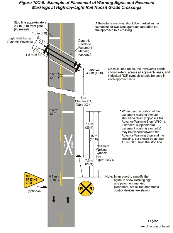
Figure 10C-5. Example of Placement of Warning Signs and Pavement Markings at Highway-Light Rail Transit Grade Crossings
This figure shows an example of placement of warning signs and pavement markings at highway-light rail transit grade crossings.
The figure shows a segment of a vertical two-lane roadway. At the top of the figure, a symbol of a transit track is shown, placed diagonally across the roadway at an acute angle, slanting from the northwest on the left to the southeast on the right. A legend shows a black arrow indicating the direction of travel in the lanes. Black arrows on the roadway show the direction of travel as one lane in each direction. At the top of the figure, the opposing lanes are shown separated by a solid double yellow line. In the middle of the figure, the opposing lanes are shown separated by a broken yellow line to the left of a solid yellow line. At the bottom of the figure, the opposing lanes are shown separated by a broken yellow line. A note states: "A three-lane roadway should be marked with a centerline for two-lane approach operation on the approach to a crossing."
At the bottom of the figure, a horizontal white line is shown extending across the right lane. It is shown as a dimension of 0.6 m (2 ft) wide. To the left of the roadway opposite the white line, a yellow isosceles triangular sign is shown with a black border and the message "NO PASSING ZONE" in black on three lines and marked as optional. A note states: "In an effort to simplify the figure to show warning sign and pavement markings placement, not all required traffic control devices are shown."
Beyond the horizontal white line, a white pavement marking symbol composed of a large white "X" with a white "R" to the left and right of it and another horizontal white line are shown. The second horizontal line is also shown as a dimension of 0.6 m (2 ft) wide. The distance from the near edge of the first horizontal line to the far edge of the second is shown as a dimensioned distance of 15 m (50 ft). The center of the "X" is shown as a dimension of 7.5 m (25 ft) from the near edge of the first white horizontal line and the far edge of the second horizontal line. At the beginning of the "RXR" marking, a round yellow sign with a black border and legend is shown to the right of the roadway. A black "X" covers the sign, and two "R's" are shown in the left and right quadrants of the sign. A notes states "See Chapter 2C, Table 2C-4" for the distance from this sign to the edge of the stop line in advance of the transit track. Notes next to the pavement marking symbol state: "See Figure 10C-6. When used, a portion of the pavement marking symbol should be directly opposite the Advance Warning Sign (W10-1). If needed, supplemental pavement marking symbol(s) may be placed between the Advance Warning Sign and the crossing, but should be at least 15 m (50 ft) from the stop line."
Beyond the "RXR" marking, a horizontal white line is shown extending across the right lane in advance of the transit track. It is shown as a dimension of 0.6 m (2 ft) wide. A second horizontal line is shown on the far side of the transit track. The horizontal lines are shown as a dimensioned distance of approximately 2.4 m (8 ft) from the gate (if present) and 4.6 m (15 ft) from the outside edge of the transit track.
Beyond the first horizontal line, a symbol of a transit track is shown, placed diagonally across the roadway at an acute angle, slanting from the northwest on the left to the southeast on the right. The light rail transit vehicle dynamic envelope is shown. A white transverse band on the pavement is shown extending across the entire roadway on each side of the transit track. These lines are shown at the edge of the dynamic envelope or 1.8 m (6 ft) from the outside edge of the track. A note states: "On multi-lane roads, the transverse bands should extend across all approach lanes, and individual RXR symbols should be used in each approach lane."
