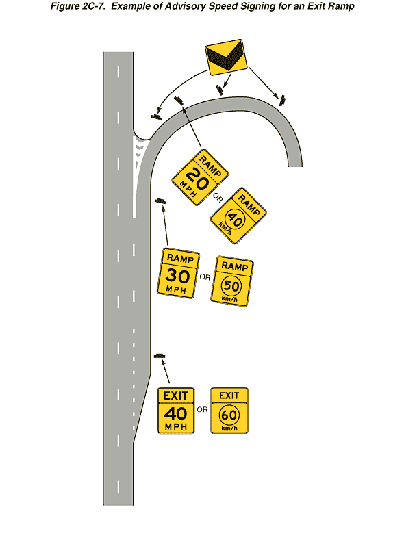
Figure 2C-7. Example of Advisory Speed Signing for an Exit Ramp
This figure shows two vertical lanes of a divided highway. The two lanes are separated from each other by a broken white line. Black inverted Ts denote signs.
Near the bottom of the figure, a deceleration lane tapers to the right of the right lane, leading to a right exit ramp. The deceleration lane runs parallel to the right lane and is separated from it by a dotted white line that changes to a broken white line. Along the top third of the exit lane, the broken white line splits in two to form a V-shaped island with forward-pointing white chevron markings on the pavement. The exit ramp then curves to the right into a semicircular shape.
At the point where the deceleration lane becomes parallel to the right lane, an Exit Ramp sign is shown to the right of the deceleration lane. The sign is shown with the word "EXIT" and the legend "40 MPH." To the right of this sign, the word "OR" is shown and another sign. This is the metric alternate, with the legend "60 km/h."
Beyond these signs at the point where the island begins, a Ramp Speed sign is shown to the right of the deceleration lane. The sign is shown with the word "RAMP" and the legend "30 MPH." To the right of this sign, the word "OR" is shown and another sign. This is the metric alternate, with the legend "50 km/h."
The deceleration lane then is shown curving to the right to become the exit ramp. To the left of the exit ramp, a vertical rectangular yellow sign is shown with a right-pointing black chevron. Just beyond this sign, another Ramp Speed sign is shown, with the legend shown as "20 MPH" and the metric alternate as "40 km/h."
Farther along the curve, another chevron sign is shown to the left of the roadway followed by another farther along the curve.
