
Figure 3B-31. Examples of Advance Warning Markings for Speed Humps
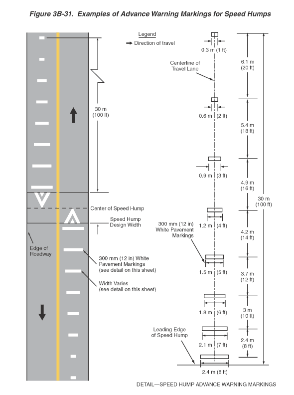
This figure illustrates examples of advance warning markings for speed humps.
A vertical two-lane roadway is shown. Arrows show that the direction of travel is one lane in each direction. A solid double yellow line separates the two lanes.
In the middle of the figure, a speed hump is shown with white speed hump markings for each of the two lanes, with the base of the "v" for each direction shown at the near edge of the speed hump and the point of the "v" for each direction at the center of the speed hump. In each direction, a series of eight white horizontal lines is shown on the pavement, each centered on the centerline of each travel lane. The thickness of each line marking is shown as 300 mm (12 in) wide.
The width of the lines graduates from short to long as they approach the speed hump:
- The first line, 30 m (100 ft) in advance of the leading edge of the speed hump, is the narrowest, shown as 0.3 m (1 ft) wide.
- The second line is shown as 6.1 m (20 ft) closer to the hump and 0.6 m (2 ft) wide.
- The third line is shown as 5.4 m (18 ft) closer to the hump and 0.9 m (3 ft) wide.
- The fourth line is shown as 4.9 m (16 ft) closer to the hump and 1.2 m (4 ft) wide.
- The fifth line is shown as 4.2 m (14 ft) closer to the hump and 1.5 m (5 ft) wide.
- The sixth line is shown as 3.7 m (12 ft) closer to the hump and 1.8 m (6 ft) wide.
- The seventh line is 3 m (10 ft) closer to the hump and is 2.1 m (7 ft) wide.
- The eighth and last line is shown as 2.4 m (8 ft) closer to the hump and 2.4 m (8 ft) wide.