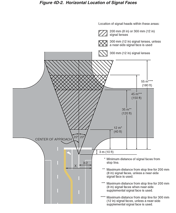
Figure 4D-2. Horizontal Location of Signal Faces
This figure illustrates the horizontal location of signal faces.
The figure shows the area located between two lines intersecting the center of the approach to an intersection at a point shown as a dimension of 3 m (10 ft) behind the stop line, one shown as making an angle of 20 degrees to the right of the center of the approach extended, and the other shown as making an angle of 20 degrees to the left of the center of the approach extended. The center of the approach is shown as one-half of the approach width, which is shown as including the parking lane and the supplemental left-turn lane.
The figure also shows the minimum distance of signal faces from the stop line as a dimension of 12 m (40 ft).
The area between the 20-degree angled lines is denoted as the location of signal heads for various conditions:
- The maximum distance from the stop line for 200 mm (8 in) signal faces is shown as a dimension of 35 m (120 ft) unless a near-side signal face is used, in which case the maximum distance is shown as a dimension of 45 m (150 ft).
- The maximum distance from the stop line for 300 mm (12 in) signal faces is shown as a dimension of 45 m (150 ft) unless a near-side supplemental signal face is used.
