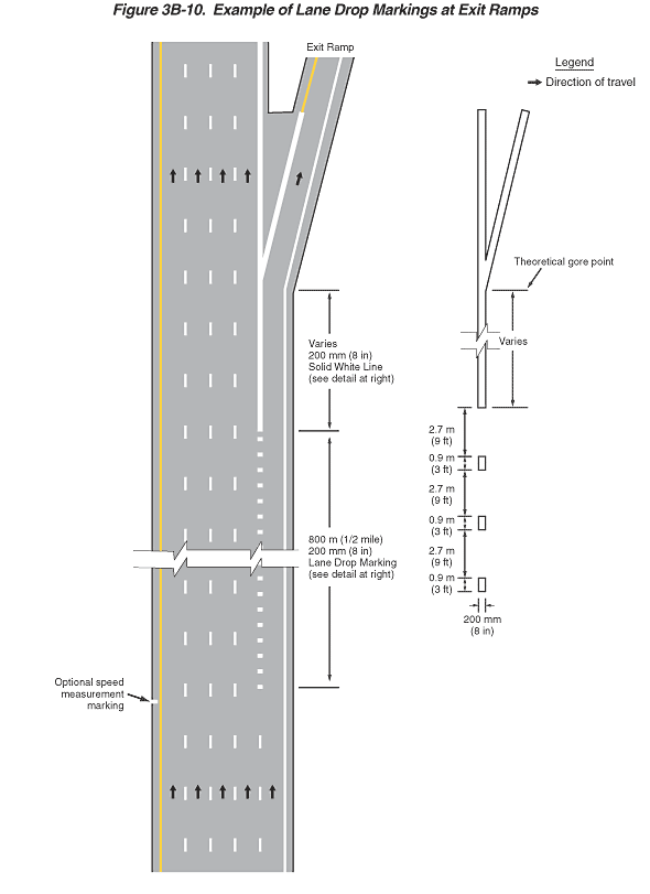
Figure 3B-10. Example of Lane Drop Markings at Exit Ramps
This figure illustrates an example of lane drop markings at exit ramps.
The figure shows a vertical highway with five lanes of one direction of a divided highway, four lanes of which continue through past an exit ramp, and the rightmost of which angles off to the right to become the exit ramp. Arrows indicate that the direction of travel is from the bottom of the figure to the top. A solid yellow line is shown to the left of the leftmost through lane, a solid white line is shown to the right of the rightmost travel lane, and the through lanes are shown separated from each other by a broken white line. An optional white speed measurement marking is shown to the left of the solid yellow line on the left shoulder of the highway.
In the middle of the figure, the far right lane is shown becoming the deceleration lane, leading to a right exit ramp. The deceleration lane is shown separated from the rightmost of the four remaining through lanes by a dotted white line. This dotted line is labeled as "200 mm (8 in) Lane Drop Marking (See detail at right)." It continues for a distance labeled as "800 m (1/2 mile)" and then becomes a solid white line that is labeled as "200 mm (8 in) Solid White Line (See detail at right)." The rightmost lane then is shown angling off to the right and becoming the exit ramp. An arrow indicates the direction of travel on the ramp.
An inset diagram shows the detail of the wide dotted white line with segments that are shown as a dimension of 200 mm (8 in) wide, 0.9 m (3 ft) long, and 2.7 m (9 ft) apart. This diagram also shows that the length of the solid white line in advance of the theoretical gore point at the exit varies.
A legend shows a black arrow indicating the direction of travel in the lanes.
