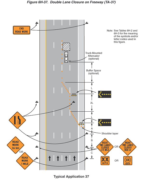
Figure 6H-37. Double Lane Closure on Freeway (TA-37)
This figure illustrates an example of a double lane closure on a freeway. A legend under the figure states that this is Typical Application 37. A note states "See Tables 6H-2 and 6H-3 for the meaning of the symbols and/or letter codes used in this figure."
The figure shows a vertical four-lane freeway with all lanes of traffic in one direction. Upward-pointing black arrows in each lane denote the direction of traffic. The lanes are shown separated by broken white lines. Left and right shoulders are shown next to the two outside lanes. The left shoulder is shown separated from the left lane by a solid yellow line. The right shoulder is shown separated from the right shoulder by a solid white line.
At the bottom of the figure and outside the left and right shoulders, two black inverted "Ts" are shown denoting signs. The signs are shown as diamond-shaped orange signs with black borders and the words "ROAD WORK 1 MILE" in black or the metric alternate "1.6 km." These signs are shown at a dimensioned distance C in advance of sign assemblies outside the left and right shoulders. The sign assemblies are composed of a diamond-shaped orange sign with a black border and the words "RIGHT TWO LANES CLOSED ½ MILE" in black and the metric alternate "RIGHT TWO LANES CLOSED 800 m" shown above a square orange plaque with a black border and the words "XX MPH" in black and the metric alternate "XX km/h" with the letters "XX" inside a black circle. These signs are shown at a dimensioned distance B in advance of another set of signs outside the left and right shoulders. They show a thick, vertical straight line on the left; a thick, vertical line on the right that angles toward the left half way up; and a thin, short vertical dotted line between them that is the length of the vertical section of the line on the right, denoting a lane ends. The two lane ends signs are shown at a dimensioned distance A in advance of a horizontal rectangular black arrow panel with a directional yellow arrow pointing to the left shown on the right shoulder.
Just in advance of the black arrow panel, a series of orange squares, denoting channelizing devices, is shown extending from and tapering from the far right edge of the shoulder to the left edge of the shoulder approximately even with the arrow panel. From the end of the shoulder taper, another taper of channelizing devices is shown completely crossing the right lane at a dimensioned distance L. A series of channelizing devices is shown continuing along the white broken lines separating the right two traffic lanes for a dimensioned distance 2 L. Midway between this series of channelizing devices, two lane ends symbol signs are shown. One is shown outside the left shoulder, and the other is shown in the closed right traffic lane. A black arrow panel with a directional yellow arrow pointing to the left is shown at a dimensioned distance 2 L beyond the end of the right lane taper in the middle of the right lane. At this point, a series of closely spaced channelizing devices is shown extending diagonally to the left at a dimensioned distance L from the broken white line separating the two right traffic lanes to the broken white line separating the two center lanes. From this point, a series of channelizing devices is shown continuing along the broken white line through an undimensioned buffer space labeled optional. At the end of the buffer space in the middle right lane, the symbol for a work vehicle is shown. Attached to the rear of the work vehicle symbol, the symbol for a truck-mounted attenuator labeled optional is shown. Directly beyond the work vehicle symbol in the same lane, a white square with black diagonal lines is shown denoting a work space. Beyond the work space and at the top of the figure, two horizontal rectangular orange signs with black borders and the words "END ROAD WORK" in black are shown outside the left and right shoulders.
