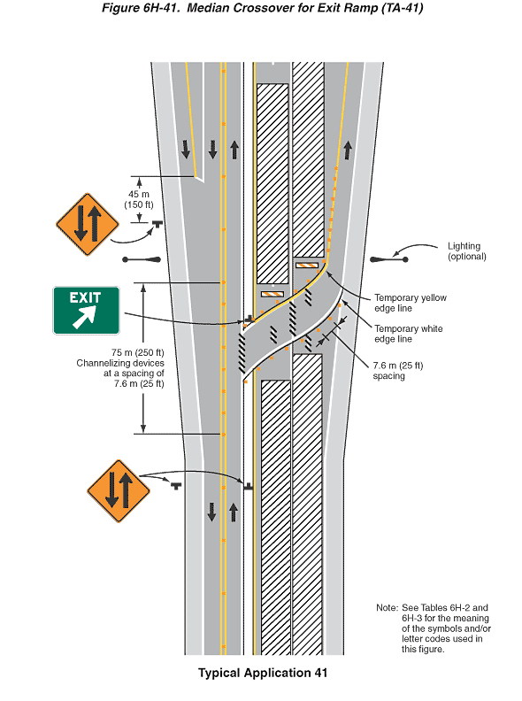
Figure 6H-41. Median Crossover for Exit Ramp (TA-41)
This figure illustrates an example of a median crossover for an exit ramp. A legend under the figure states that this is Typical Application 41. A note states "Note: See Tables 6H-2 and 6H-3 for the meaning of the symbols and/or letter codes used in this figure."
This figure shows a vertical four-lane divided highway with a median dividing two lanes, an entrance ramp, and a shoulder on the left of the figure and two lanes, an exit ramp, and a shoulder on the right. Black arrows denote the direction of travel in all lanes. The shoulders are shown separated from the travel lanes by a solid white line. The two opposing lanes on the left are shown separated by a solid double yellow line.
At the top of the figure, an entrance ramp on the outside of the southbound right lane is shown tapering to join the two southbound travel lanes. A downward-pointing black arrow shows that the direction of travel on the entrance ramp is southbound. Upward-pointing black arrows on the outside lane show that the direction of travel is southbound, and upward-pointing black arrows on the inside lane show that the direction of travel is northbound. These opposing lanes are shown separated by a solid double yellow line, and a series of orange squares denoting channelizing devices is shown along the entire length of the line. The northbound lane is shown separated from the median by a solid white line. At the top of the figure, the southbound lane is shown separated from the entrance ramp by a solid white line. To the outside of the shoulder of the entrance ramp, a black "T" is shown denoting a sign at a dimensioned distance of 45 m (150 ft) beyond the point where the entrance ramp is shown merging with the southbound lane. This sign is shown as a diamond-shaped orange sign with a black border and a downward-pointing black arrow to the left of an upward-pointing black arrow, denoting two-way traffic. Just beyond this sign, a black oar-shaped symbol denoting a luminaire is shown to the outside of the shoulder of the acceleration lane.
Just south of the luminaire symbol, the channelizing devices are shown at a dimensioned spacing of 7.6 m (25 ft) continuing for a dimensioned distance of 75 m (250 ft) along the solid double yellow line. This distance is shown including the point where a northbound lane crosses over the median to form an exit ramp on the right side of the figure. On the northern side of the crossover, a sign is shown on the median facing northbound travel lanes. The sign is shown as a horizontal rectangular green sign with a white border and the word "EXIT" in white above a diagonal white arrow pointing up and to the right. This sign is shown where the northbound lane crosses over the median. This crossover lane is shown curving to the right and crossing the median and the two travel lanes on the right side of the figure to merge with an exit lane to the right of the travel lanes. A yellow line denoted as a temporary yellow edge line is shown on the left side of the crossover lane, and a white line denoted as a temporary white edge line is shown on the right side. A series of channelizing devices is shown to the outside of both sides of the lane at a dimensioned spacing of 7.6 m (25 ft). Black diagonal lines are shown obscuring the regular white lane markings in the crossover.
Farther south on the left side of the figure and beyond the crossover, a Two-Way Traffic symbol sign is shown outside of the southbound shoulder facing southbound traffic. At the same point on the median, another Two-Way Traffic symbol sign is shown facing northbound traffic.
At the bottom of the figure, two vertical rectangles with diagonal black and white stripes denoting work spaces are shown in the two northbound travel lanes on the right side of the figure. An exit ramp is shown to the right of the two travel lanes. At the mid-point of the figure, the lane from the northbound lane on the left side of the figure is shown crossing over the two lanes on the right side and merging with an exit ramp to the right of the these two lanes. Where the crossover merges with the exit ramp, a black oar-shaped luminaire symbol labeled optional is shown to the right of the right shoulder. Beyond this point on the exit ramp, a series of closely spaced orange squares denoting channelizing devices is shown along the temporary solid yellow edge line to the left of the exit ramp. In the two travel lanes beyond the crossover lane, two work spaces are shown extending to the top of the figure.
