2009 Edition Part 3 Figure 3B-2. Examples of Four-or-More Lane, Two-Way Marking Applications

Figure 3B-2. Examples of Four-or-More Lane, Two-Way Marking Applications
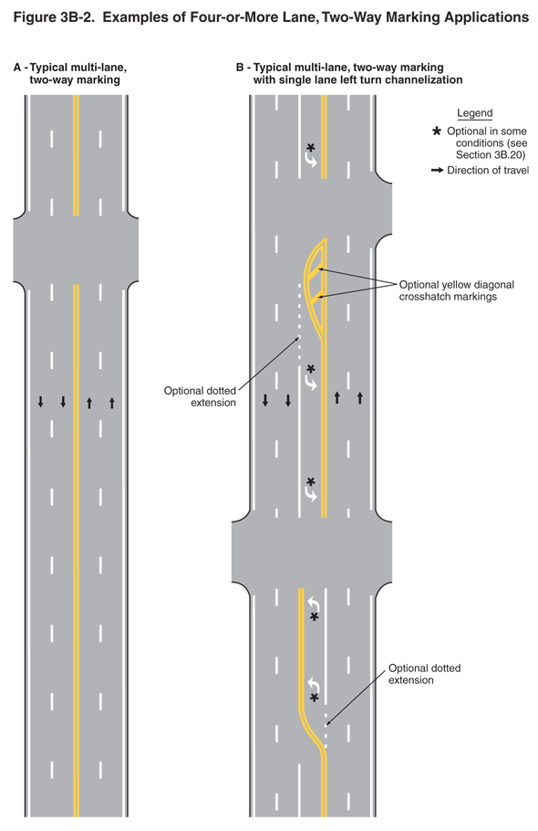
This figure illustrates two examples of pavement marking applications on two-way roadways with four or more lanes.
A legend shows a black arrow indicating the direction of travel in the lanes and an asterisk denoting "optional."
Two vertical roadways are shown, A and B:
- Example A shows "typical multi-lane, two-way marking." A four-lane roadway is shown. Arrows show that the direction of travel is two lanes in each direction. The roadway has a centerline marking of a solid double yellow line. A broken white line separates lanes traveling in the same direction. A solid white line is marked on the outside edge of each right lane.
- Example B shows "typical multi-lane, two-way marking with single lane left turn channelization." A five-lane roadway is shown with the fifth, center lane used for left turns. Arrows show that the direction of travel is two through lanes in each direction and left turns from the center lane. The roadway has markings of a solid double yellow line and alternating left turn channels marked with a solid white line to separate the turn lane from through traffic lanes traveling in the same direction. An optional dotted extension to the solid white line is shown where the left turn channels begin. An island is shown formed by the solid double yellow lines at the base of the left turn channel. This island is shown with optional yellow diagonal crosshatch markings. The turn lanes have white left-turn arrows marked on the pavement. A note states that these are "optional in some conditions (see Section 3B.20)." A broken white line separates through lanes traveling in the same direction.
