2009 Edition Part 3 Figure 3B-5. Example of Application of Three-Lane, Two-Way Marking for Changing Direction of the Center Lane

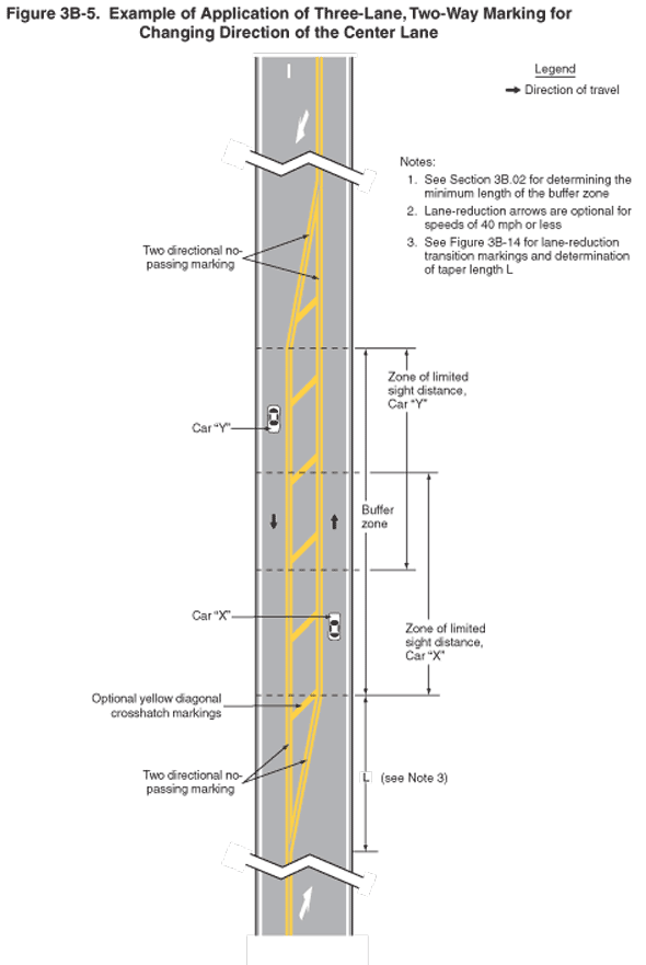
Figure 3B-5. Example of Application of Three-Lane, Two-Way Marking for Changing Direction of the Center Lane
This figure illustrates pavement markings for changing direction of the center lane of a three-lane, two-way roadway.
A legend shows a black arrow indicating the direction of travel in the lanes.
Segments of a vertical three-lane roadway are shown. A solid double yellow line is shown separating each lane from the others with the notation "Two directional no passing marking." The exception to that, at the top of the figure, is one segment of a broken white line shown separating the two southbound lanes.
Two southbound lanes are shown transitioning to one lane. Before the taper begins, a white arrow is shown marked on the pavement pointing diagonally to the outer edge of the outside lane. A solid double yellow line is shown adjacent to the southbound lane in this taper and has a notation of "Two directional no passing marking." This taper is shown ending at the northern end of a segment labeled "Buffer zone" and the northern end of a segment labeled "Zone of limited sight distance, Car 'Y,' " which extends southward approximately 2/3 the length of the buffer zone.
The two tapers and buffer zone between the solid double yellow lines are shown with optional yellow diagonal crosshatch markings.
From the bottom of the figure, two northbound lanes are shown transitioning to one lane. Before the taper begins, a white arrow is shown marked on the pavement pointing diagonally to the outer edge of the outside lane. A solid double yellow line is shown adjacent to the northbound lane in this taper and has a notation of "Two directional no passing marking" and is marked as "L," with a note to "see Note 3." This taper is shown ending at the southern end of a segment labeled "Buffer zone" and the southern end of a segment labeled "Zone of limited sight distance, Car 'X,' " which extends northward approximately 2/3 of the length of the buffer zone.
Car "X" is shown in the northbound single lane in the initial portion of the "Zone of limited sight distance, Car 'X.' " Car "Y" is shown in the southbound single lane in the initial portion of the "Zone of limited sight distance, Car 'Y.' "
The following notes are listed:
- See Section 3B.02 for determining the minimum length of the buffer zone
- Lane-reduction arrows are optional for speeds of 40 mph or less
- See Figure 3B-14 for lane-reduction transition markings and determination of taper length L
