2009 Edition Part 3 Figure 3C-2. Lane-Use Arrow Pavement Marking Options for Roundabout Approaches

Figure 3C-2. Lane-Use Arrow Pavement Marking Options for Roundabout Approaches
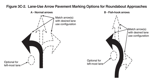
This figure shows two examples of lane-use arrow pavement marking options for roundabout approaches.
The first example is labeled "A - normal arrows" and shows a vertical black arrow curving up and to the left. The arrow is shown curving around a circle formed by a broken black line, labeled "optional for left-most lane." Two arrows formed by broken black lines are shown attached to the vertical shaft of the black arrow. One points up, and the other curves to the right. They are labeled "Match arrows with desired lane use configuration."
The second example is labeled "B - fish-hook arrows" and shows a vertical black arrow curving up and then slightly to the right and then to the left. The arrow is shown curving around a circle formed by a broken black line, labeled "optional for left-most lane." Two arrows formed by broken black lines are shown attached to the curving black arrow. One is attached to the top of the left curve and curves slightly to the right and then up. The other is attached to the base of the black arrow and curves to the right. They are labeled "Match arrows with desired lane use configuration."
