2009 Edition Part 3 Figure 3C-8. Example of Markings for a Two-Lane Roundabout with a Double Right Turn

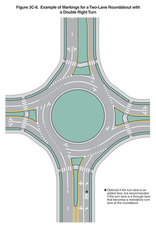
Figure 3C-8. Example of Markings for a Two-Lane Roundabout with a Double Right Turn
This figure illustrates markings for a two-lane roundabout with a double right turn.
The figure shows a green central island surrounded by a circular roadway. A narrow band shown as composed of a contrasting pavement texture separates the island from the circular roadway.
Roadways are shown entering the roundabout from the north, south, east, and west. A narrow landscape buffer borders the outsides of the roadways. A triangular splitter island separates the opposing travel lanes of each road where it intersects the circular roadway. A crosswalk composed of a row of closely spaced white lines parallel to the flow of traffic is shown crossing all lanes and the narrow part of each splitter island.
Around the outer edge of the circular roadway, a solid white line is shown across the base of each splitter island, a wide dotted white line is shown intersecting each of the entering lanes, and no line is shown intersecting the exiting lanes.
The roadway entering the roundabout from the north is shown with two lanes on the right side of the splitter island entering the roundabout and one lane to the left exiting the roundabout. The roadways entering the roundabout from the west, south, and east are shown with two lanes on the right side of each splitter island entering the roundabout and two lanes to the left exiting the roundabout. The lanes entering the roundabout from the north are shown separated by a broken white line, which changes to a solid white line on both sides of the crosswalk. The lanes entering the roundabout from the south are shown separated by a solid white line, and the lanes exiting the roundabout to the south are shown separated by a broken white line, which changes to a solid white line on both sides of the crosswalk. The lanes entering and exiting the roundabout from the west and east are shown separated by a solid white line. White arrows are shown marked on the pavement of the each lane entering the roundabout in advance of the crosswalk. On the roadways entering the roundabout from the north, west, and east, a two-direction white arrow in each left lane is shown pointing to the left and straight ahead, and a two-direction white arrow in each right lane is shown pointing straight ahead and to the right. On the roadway entering the roundabout from the south, three-direction arrows marked on the pavement of the left lane are shown pointing to the left, straight ahead, and to the right. On the roadway entering the roundabout from the south, a right-turn arrow is shown marked on the pavement of the right lane, followed by the word "ONLY" and another right-turn arrow. The word "ONLY" is noted as "Optional if the turn lane is an added lane, but recommended if the turn lane is a through lane that becomes a mandatory turn lane at the roundabout."
Except opposite the splitter island on the roadway from the east, the circular roadway is shown as two lanes, with a solid white line separating the two lanes opposite the splitter islands and changing to a normal broken white line opposite the points where lanes from the roadways enter the roundabout. Two-direction white arrows pointing to the left and straight ahead are shown marked on the pavement of the left lane, and white arrows pointing straight ahead are shown marked on the pavement of the right lane of the circular roadway. Opposite the splitter island on the roadway from the east, the circular roadway is shown as one lane, with a two-direction white arrow pointing to the left and straight ahead shown marked on the pavement.
