2009 Edition Part 3 Figure 3D-2. Markings for Buffer-Separated Preferential Lanes (Sheet 2 of 2)

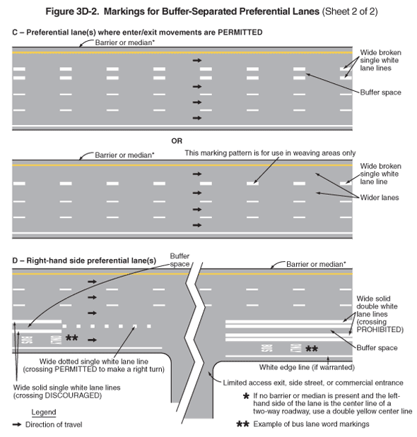
Figure 3D-2. Markings for Buffer-Separated Preferential Lanes (Sheet 2 of 2)
This figure illustrates two examples of markings for barrier-separated preferential lanes.
Two horizontal roadways are shown, C and D. A legend shows a black arrow indicating the direction of travel in the lanes.
- Figure C is labeled "Preferential lane(s) where enter/exit movements are PERMITTED." The figure shows a four-lane horizontal roadway. A solid yellow line separates the left travel lane from a shoulder, a solid white line separates the right travel lane from a shoulder, and a broken white line separates the three rightmost lanes from each other. The left shoulder is bordered on the outside by a line labeled "barrier or median" with a note that states: "If no barrier or median is present and the left-hand side of the lane is the center line of a two-way roadway, use a double yellow center line." Arrows indicate that the direction of travel is from the left of the figure to the right. The leftmost preferential lane is shown separated from the other three by a wide broken single white lane line to the right of the left lane, a buffer space, and another wide broken single white lane line that is to the left of the left through lane. The word "OR" is shown below this figure, with another figure of the same four-lane horizontal roadway. The left preferential lane and the left through lane are shown as wider lanes, and they are separated by a wide broken single white lane line. A note states: "This marking pattern is for use in weaving areas only."
- Figure D is labeled "Right-hand side preferential lane(s)." The figure shows segments of a four-lane horizontal roadway with a vertical roadway intersecting the rightmost lane. The vertical roadway is labeled as a "limited access exit, side street, or commercial entrance." A solid yellow line separates the left travel lane from a shoulder, a solid white edge line separates the right travel lane from a shoulder, noted "if warranted," and a broken white line separates the three leftmost lanes from each other. The left shoulder is bordered on the outside by a line labeled "barrier or median" with a note that states: "If no barrier or median is present and the left-hand side of the lane is the center line of a two-way roadway, use a double yellow center line." Arrows indicate that the direction of travel is from the left of the figure to the right. On the left side of the figure, in advance of the intersection, the rightmost preferential lane is shown separated from the other three by a wide solid single white lane line to the right of the right through lane, a buffer space, and another wide solid single white lane line that is to the left of the right preferential lane. The solid single lane lines are noted as "crossing DISCOURAGED." Closer to the intersection, the white lane lines on either side of the buffer space are shown changing to a wide dotted single white lane line, noted as "crossing PERMITTED to make a right turn," in the middle of the buffer zone. This line does not continue across the intersection with the vertical roadway. On the right side of the figure, on the east side of the intersection, the right preferential lane is shown separated from the other three by a wide solid double white lane line to the right of the left lane, a buffer space, and another wide solid double white lane line that is to the left of the right preferential lane. The solid double lane lines are noted as "crossing PROHIBITED." In the right preferential lane, words are shown marked on the pavement in white on two lines, progressing in the direction of travel from the word "BUS" to the word "ONLY." These words are noted as an "example of bus lane word markings.
Back to: Sheet 1
