2009 Edition Part 4 Figure 4D-4. Lateral and Longitudinal Location of Primary Signal Faces

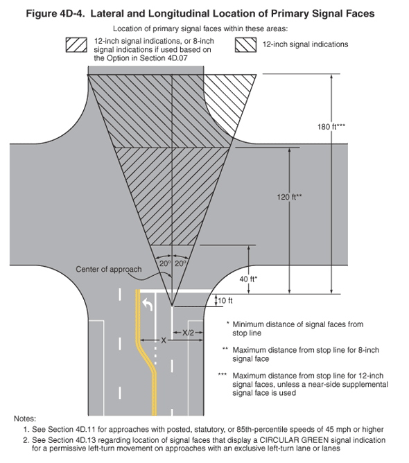
Figure 4D-4. Lateral and Longitudinal Location of Primary Signal Faces
This figure illustrates the lateral and longitudinal location of primary signal faces.
The figure shows the area located between two lines intersecting the center of the approach to an intersection at a point shown as a dimension of 10 ft behind the stop line, one shown as making an angle of 20 degrees to the right of the center of the approach extended, and the other shown as making an angle of 20 degrees to the left of the center of the approach extended. The center of the approach is shown as one-half of the approach width, which is shown as including the parking lane and the supplemental left-turn lane.
The figure also shows the minimum distance of signal faces from the stop line as a dimension of 40 ft.
The area between the 20-degree angled lines is denoted as the location of signal heads for various conditions:
- The maximum distance from the stop line for 12-inch signal faces or 8-inch signal faces if used based on the option in Section 4D.07, is shown as a dimension of 120 ft.
- The maximum distance from the stop line for 12-inch signal faces is shown as a dimension of 180 ft unless a near-side supplemental signal face is used.
The following notes are included:
- See Section 4D.11 for approaches with posted, statutory, or 85th-percentile speeds of 45 mph or higher.
- See Section 4D.13 regarding location of signal faces that display a CIRCULAR GREEN signal indication for a permissive left-turn movement on approaches with an exclusive left-turn lane or lanes.
