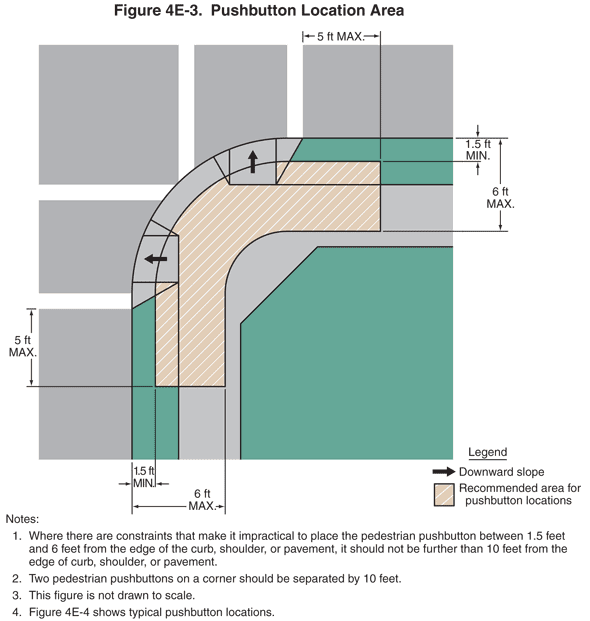
2009 Edition Part 4 Figure 4E-3. Pushbutton Location Area

Figure 4E-3. Pushbutton Location Area
This figure contains an example of pushbutton location area.
A legend at the bottom of the page shows a horizontal black arrow labeled "Downward Slope" and a diagonally striped shaded area labeled "Recommended Area for Pushbutton Locations."
The following notes are included:
- Where there are constraints that make it impractical to place the pedestrian pushbutton between 1.5 feet and 6 feet from the edge of the curb, shoulder, or pavement, it should not be further than 10 feet from the edge of curb, shoulder, or pavement.
- Two pedestrian pushbuttons on a corner should be separated by 10 feet.
- This figure is not drawn to scale.
- Figure 4E-4 shows typical pushbutton locations.
The figure shows a plan view of one corner of a 90-degree intersection of two streets, each with a sidewalk that is separated from the street by a green strip. Two sets of parallel white lines denoting crosswalks are shown, one horizontal to the left of the corner, and one vertical above the corner. On the corner radius, two curb-cut ramps are shown, one aligned with the east-west crosswalk and one aligned with the north-south crosswalk. A left-pointing black arrow is shown in the center of the horizontal ramp, and an upward-pointing black arrow is shown in the center of the vertical ramp, both denoting the downward slope.
The recommended area marked for pushbutton locations over the sidewalk is shown as a dimensioned distance of 1.5 ft MIN. to 6 ft MAX from the edge of the curb and onto the sidewalk and 5 ft MAX. from the outside edge of each crosswalk.
