
2009 Edition Part 4 Figure 4G-1. Sequence for an Emergency-Vehicle Hybrid Beacon
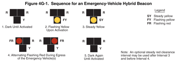
Figure 4G-1. Sequence for an Emergency-Vehicle Hybrid Beacon
This figure shows the six intervals in a sequence for an emergency-vehicle hybrid beacon.
Each interval is shown as a signal face having three lenses: two horizontally aligned with a third centered under them.
A note states: "An optional steady red clearance interval may be used after Interval 3 and before Interval 4."
The first interval is labeled "1. Dark Until Activated." It shows black squares for a circular red signal (not shown) to the left of a circular red signal (not shown) above a black square for a circular yellow signal (not shown).
The second interval is labeled "2. Flashing Yellow Upon Activation." It shows black squares for a circular red signal (not shown) to the left of a circular red signal (not shown) above a circular yellow signal labeled "flashing yellow."
The third interval is labeled "3. Steady Yellow." It shows black squares for a circular red signal (not shown) to the left of a circular red signal (not shown) above a circular yellow signal labeled "steady yellow."