2009 Edition Part 6 Figure 6H-34. Lane Closure with a Temporary Traffic Barrier (TA-34)

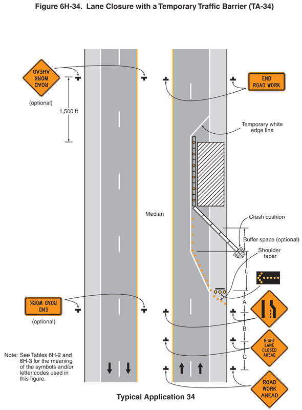
Figure 6H-34. Lane Closure with a Temporary Traffic Barrier (TA-34)
This figure illustrates an example of lane closure with atemporary traffic barrier. A legend under the figure states that this isTypical Application 34. A note states "See Tables 6H-2 and 6H-3 for themeaning of the symbols and/or letter codes used in this figure."
This figure shows a vertical divided roadway with two lanesof traffic in each direction. Downward-pointing black arrows in the two leftlanes and upward-pointing arrows in the two right lanes denote the direction oftraffic. The opposing lanes are separated by a median. A shoulder is shown tothe right of each right-hand lane. The shoulders are shown separated from theright lanes by a solid white line. The two lanes in each direction are shownseparated from each other by a broken white line. The two left-hand lanes areshown separated from the median by a solid yellow line.
At the bottom of the figure to the right of the shoulder andto the left of the solid yellow line on the median, two black inverted"Ts" are shown denoting signs. The signs are shown as diamond-shapedorange signs with black borders and the words "ROAD WORK AHEAD" inblack. These signs are shown at a dimensioned distance C in advance of two morediamond-shaped orange signs with black borders and the words "RIGHT LANECLOSED AHEAD" in black. These signs are shown at a dimensioned distance Bin advance of two more diamond-shaped orange signs with black borders. Theyshow a thick, vertical straight line on the left; a thick, vertical line on theright that angles toward the left half way up; and a thin, short verticaldotted line between them that is the length of the vertical section of the lineon the right, denoting a lane ends. At this point, a series of orange squaresdenoting channelizing devices are shown beginning at the right edge of theright shoulder and tapering to the left for a dimensioned distance A to thesolid white line separating the shoulder from the right lane. Where thechannelizing devices cross the solid white line between the shoulder and theright lane, a horizontal rectangular black arrow panel with a yellowdirectional arrow pointing to the left is shown across the shoulder. At thissame point, the channelizing devices are shown tapering to the left for adimensioned distance L to the broken white line between the northbound lanes.They then are shown continuing through a buffer space labeled optional untilthey come to a series of closely spaced white rectangles with small yellow circlesrepresenting temporary barriers with warning lights.
At the point where the channelizing devices are shownjoining the broken white line between the northbound lanes, a white half ovalwith a black border and black crosshatch pattern pointing down and to the rightis shown, denoting a crash cushion. This is shown just outside the rightshoulder and directly in front of a series of connected white bars denotingtemporary barriers. The temporary barrier is shown tapering from the crashcushion across the shoulder and the right-hand lane, where it is shown joiningthe temporary barrier with warning lights. These barriers are shown continuingbeyond the work space, denoted by a vertical rectangle with diagonal blacklines, which is shown spanning the right shoulder and most of the right lane.
Where the channelizing devices are shown tapering from thesolid white line separating the shoulder and right lane, a solid temporarywhite edge line is shown paralleling the devices to their left and continuingalong the broken white line between the lanes past the work space and thentapering to the right to the solid white line between the shoulder and theright lane.
Beyond the work space and to the right of the right shoulderand on the median to the left of the solid yellow line, two horizontalrectangular orange signs with black borders are shown with the words "ENDROAD WORK" in black.
Atthe top of the figure and to the right of the right shoulder and to the left ofthe solid yellow line on the median, two black inverted "Ts" areshown denoting signs. The signs are shown as Road Work Ahead signs and arelabeled optional. These signs are shown opposite the End Road Work signs on thenorthbound lanes and are shown at a dimensioned distance of 1,500 ft in advanceof the northern edge of the work space in the northbound lanes. Beyond the workspace and crash cushion area, two more signs are shown to the right of theright shoulder and to the left of the solid yellow line on the median. Theseare shown as End Road Work signs and are labeled optional. They are shownopposite the lane ends symbol sign on the northbound lanes.
