|
|
2009 Edition Part 2 Figure 2G-9. Example of Signing for an Intermediate Entry to a Barrier- or Buffer-Separated HOV Lane

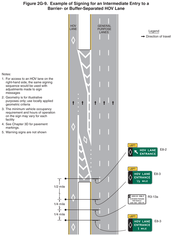
Figure 2G-9. Example of Signing for an Intermediate Entry to a Barrier- or Buffer-Separated HOV Lane
This figure shows an example of signing for an intermediate entry to a barrier- or buffer-separated HOV lane.
A legend shows a black arrow indicating the direction of travel on the highway.
The figure shows a vertical highway as a divided highway with one HOV lane to the left of a buffer or barrier to the left of three general purpose lanes. Broken white lines separate the general purpose lanes from each other. White HOV diamond symbols are shown marked on the pavement of the HOV lane.
One-third from the bottom of the figure, a theoretical gore is shown extending from the barrier north. It is shown composed of a white triangle formed by white channeling lines and white chevron markings, angling to the left. The theoretical gore is shown separating the HOV lane from an entry lane that angles from the left general purpose lane to the HOV lane. A white HOV diamond symbol is shown marked in this entry lane. The entry lane continues north and is separated from the HOV lane by a dotted white line extending from the north end of the theoretical gore. It then is shown tapering to the left and into the HOV lane by the angle of a second theoretical gore shown extending from the southern end of a barrier at the top of the figure. This theoretical gore is shown separating the HOV lane from the general purpose lanes. It is shown angling to the right and extending as a long narrow taper between the entry lane and general purpose lanes.
At the top of the figure, the exit lane has disappeared and the one HOV lane is shown to the left of a barrier to the left of the three general purpose lanes.
Four signs and sign assemblies are shown mounted over the left general purpose through lane on the approach to the entry to the HOV lane.
- At the bottom of the figure, the first sign assembly is shown as an E8-3 sign, shown as a horizontal rectangular green sign with a white border and legend. A white diamond outline symbol on a black panel is shown on the left third of the sign. This panel is shown to the left of the words "HOV LANE ENTRANCE 1 MILE" on three lines. A smaller horizontal rectangular yellow plaque with a black border and the word "LEFT" in black is shown above the top left side of the sign. This first sign is shown at a dimensioned distance of ¼ mile prior to the second sign.
- The second sign is shown at a dimensioned distance of ¼ mile prior to the third sign assembly. It is shown as an R3-13a sign, shown as a horizontal rectangular white sign with a black border and legend. A white diamond outline symbol on a black panel in the upper left quadrant of the sign is shown to the left of the words "HOV 2+ ONLY" in large letters above the words "2 OR MORE PERSONS PER VEHICLE" on two lines above the words "6 AM – 9 AM MON – FRI" on a separate bottom line.
- The third sign assembly is shown at a dimensioned distance of ½ mile prior to the fourth sign. It is shown as the same E8-3 sign assembly as the first sign assembly except the words "1/2 MILE" are shown instead of the words "1 MILE."
- The fourth sign is shown at the start of the taper into the entry lane to the HOV lane from the general purpose lane. It is shown as an E8-2, shown as a horizontal rectangular green sign with a white border and legend. A white diamond outline symbol on a black panel is shown on the left third of the sign. This panel is shown to the left of a diagonal arrow pointing to the left and up to the left of the words "HOV LANE ENTRANCE" on two lines. A smaller horizontal rectangular yellow plaque with a black border and the word "LEFT" in black is shown above the top left side of the sign.
The following notes are included:
- For access to an HOV lane on the right-hand side, the same signing sequence would be used with adjustments made to sign messages.
- Geometry is for illustrative purposes only. Use locally applied geometric criteria.
- The minimum vehicle occupancy requirement and hours of operation on the sign may vary for each facility.
- See Chapter 3D for pavement markings.
- Warning signs are not shown.
