|
|
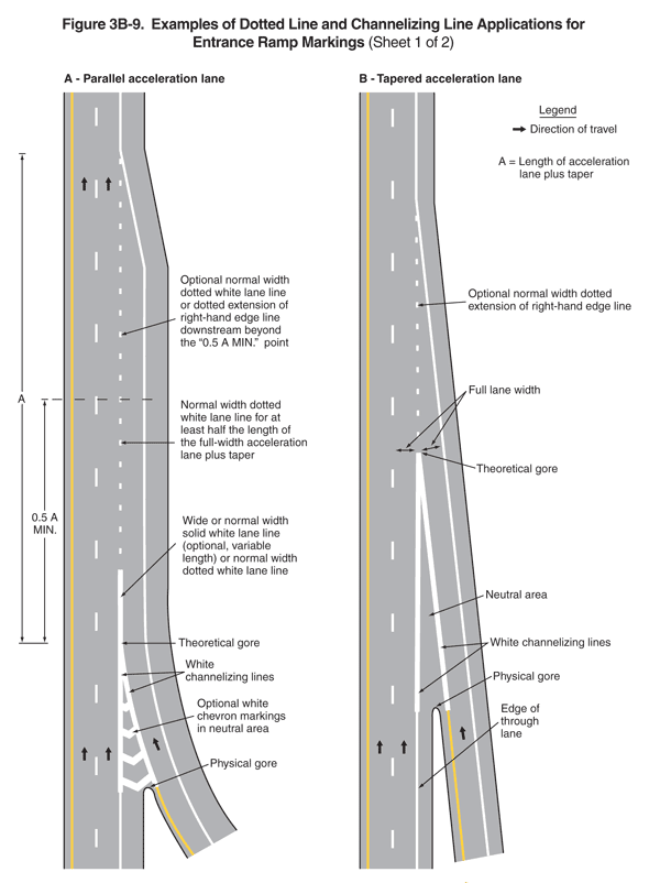
2009 Edition Part 3 Figure 3B-9. Examples of Dotted Line and Channelizing Line Applications for Entrance Ramp Markings (Sheet 1 of 2)

Figure 3B-9. Examples of Dotted Line and Channelizing Line Applications for Entrance Ramp Markings (Sheet 1 of 2)
This figure illustrates three examples of dotted line and channelizing line applications for entrance ramp markings. The figure is composed of two sheets.
Sheet 1 of the figure shows two vertical highways, examples A and B.
- A legend shows a black arrow indicating the direction of travel in the lanes.
- Example A, parallel acceleration lane, shows the two lanes of one direction of a divided highway. Arrows indicate that the direction of travel is from the bottom of the figure to the top. A solid yellow line is to the left of the leftmost through lane, a solid white line separates the rightmost travel lane from the right shoulder, and the through lanes are separated from each other by a broken white line. Near the bottom of the figure, a curving entrance ramp is added to the right of the through lanes, creating a parallel acceleration lane. Where the ramp joins the highway at the physical gore, the solid white line on the right edge of the right lane and the yellow solid line on the left edge of the entrance ramp become wide solid white lines that then become a white triangle or neutral area in front of the physical gore and then become solid "white channelizing lines" for an undimensioned distance. This triangle is shown with "optional white chevron markings in the neutral area." The solid white line extending from the triangle or neutral area is labeled the theoretical gore and notes as a "wide or normal width solid white lane line (optional, variable length) or normal width dotted white lane line." The acceleration lane runs parallel to the rightmost through lane and is separated from it by a broken white line. Notes state: "Normal width dotted white lane line for at least half the length of the full-width acceleration lane plus taper" and "Optional normal width dotted white lane line or dotted extension of right-hand edge line downstream beyond the '0.5 A MIN.' point." "A" is shown on the figure as the length of the acceleration lane plus taper. The dimension of "0.5 A MIN." is shown on the figure extending from the theoretical gore to midway on the entrance lane.
- Example B, tapered acceleration lane, shows the two lanes of one direction of a divided highway. Arrows indicate that the direction of travel is from the bottom of the figure to the top. A solid yellow line is to the left of the leftmost through lane, a solid white line separates the rightmost travel lane from the right shoulder, and the through lanes are separated from each other by a broken white line. Near the bottom of the figure, an entrance ramp is added to the right of the right through lanes at an angle, creating a tapered acceleration lane. Where the ramp joins the highway at the physical gore, the solid white line on the right edge of the right through lane and the yellow solid line on the left edge of the entrance ramp become wider, solid "white channelizing lines" for an undimensioned distance that then become a white triangle or neutral area north of the physical gore for an undimensioned distance. The point of the triangle formed by the white channelizing lines is the theoretical gore. At this point, both the right through lane and the entrance lane are full lane width. A dotted white line extends north from the theoretical gore, labeled an "optional normal width dotted extension of the right-hand edge line," and ends at the extension of the solid white on the right edge of the entrance lane.
Continue to: Sheet 2
