|
|
2009 Edition Part 3 Figure 3B-24. Examples of Standard Arrows for Pavement Markings

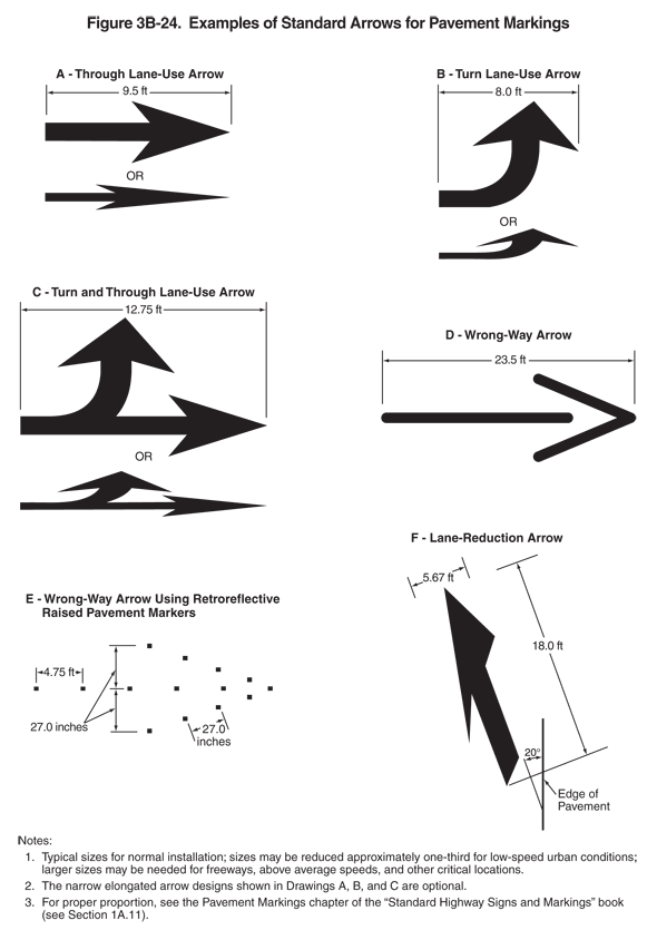
Figure 3B-24. Examples of Standard Arrows for Pavement Markings
This figure illustrates six examples of standard arrows for pavement markings. In each example, black arrows are shown.
The figure shows examples A, B, C, D, E, and F:
- Example A shows a through lane-use arrow. It is composed of a horizontal straight shaft that ends in an arrowhead, pointing to the right. It is shown as a dimension of 9.5 ft long. The word "OR" is shown below this arrow and above an arrow of the same length but of a compressed width.
- Example B shows a turn lane-use arrow. It is composed of a horizontal left-curving shaft that ends in an upward-pointing arrowhead. It is shown as a dimension of 8.0 ft long. The word "OR" is shown below this arrow and above an arrow of the same length but of a compressed width.
- Example C shows a turn and through lane-use arrow. It is composed of a horizontal shaft that branches. One branch becomes a left-curving shaft that ends in an upward-pointing arrowhead, and the other branch continues as a straight shaft that ends in an arrowhead, pointing to the right. It is shown as a dimension of 12.75 ft long. The word "OR" is shown below this arrow and above an arrow of the same length but of a compressed width.
- Example D shows a wrong-way arrow. It is composed of a horizontal straight shaft that is a thin rather than a thick line. A right-pointing arrowhead is also composed of a thin rather than thick line. It is at the right end of the shaft but is not connected to it. It is shown as a dimension of 23.5 ft long.
- Example E shows a wrong-way arrow using retroreflective raised pavement markers. A total of 14 retroreflective raised pavement markers, each denoted in the example by a small black square, are arranged in the shape of a right-pointing arrow. The markers in the shaft are shown as a dimension of 4.75 ft apart, the markers in the arrowhead are shown as a dimension of 27.0 inches apart, and the width of each half of the arrowhead, above and below the shaft, is shown as a dimension of 27.0 in.
- Example F shows a lane-reduction arrow. It is composed of a straight shaft with a diagonally shaped base that ends in an upward-pointing arrowhead. It is shown as a dimension of 18.0 ft long and 5.67 ft wide. The arrowhead is shown with a diagonally shaped base, and the left side of the arrowhead is narrower than the right. The arrow is shown in a vertical orientation but at a 20-degree left angle from the right edge of the pavement.
Notes state:
- Typical sizes for normal installation; sizes may be reduced approximately one-third for low-speed urban conditions; larger sizes may be needed for freeways, above average speeds, and other critical locations.
- A narrow elongated arrow designs shown in Drawings A, B, and C are optional.
- For proper proportion, see the Pavement Markings chapter of the "Standard Highway Signs and Markings" book (see Section 1A.11).
