|
|
2009 Edition Part 3 Figure 3F-1. Examples of Delineator Placement

Figure 3F-1. Examples of Delineator Placement
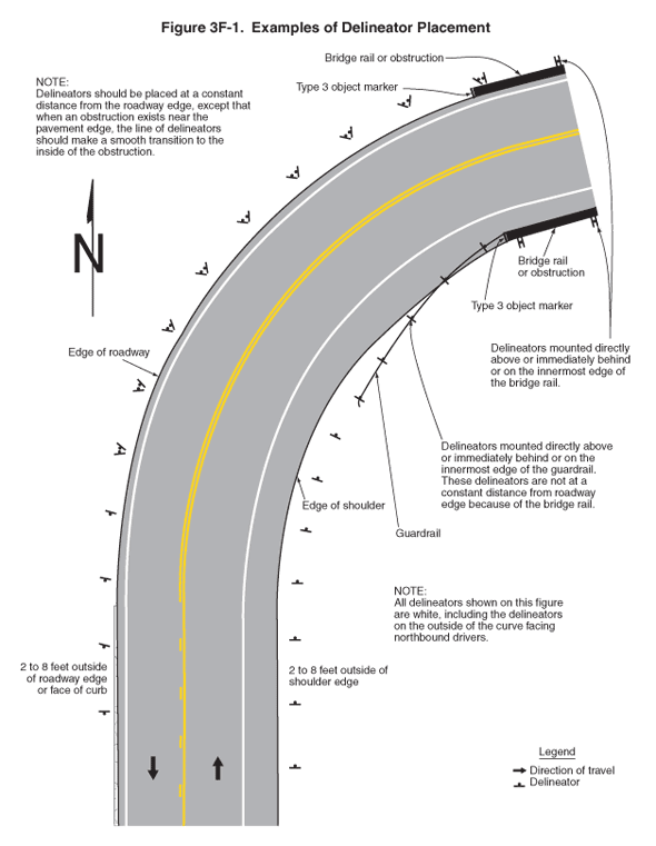
This figure illustrates examples of delineator placement.
A legend shows a black arrow indicating the direction of travel in the lanes and a symbol of a small disk centered on a short horizontal line, indicating a delineator. A note states: "All delineators shown on this figure are white, including the delineators on the outside of the curve facing northbound drivers."
The figure shows a vertical two-lane roadway that curves to the right at the top of the figure. Black arrows show that the direction of travel is one lane in each direction. At the top right of the figure, a black capital letter "N" is shown superimposed on an upward-pointing vertical black arrow, denoting the compass direction. A broken yellow line separates the two lanes at the bottom of the figure, and as the roadway begins to curve, the broken line becomes a solid double yellow line. A solid white line is shown on the outer edge of each lane. On the right side of the northbound lane, a wide shoulder is shown to the right of the solid white line.
A series of delineators is shown placed the same distance apart along each outside edge of the roadway, facing approaching traffic. Alongside the southbound direction, they are noted as 2 to 8 feet outside of roadway edge or face of curb. Alongside the northbound direction, they are noted as 2 to 8 feet outside of shoulder edge.
A note states: "Delineators should be placed at a constant distance from the roadway edge, except that when an obstruction exists near the pavement edge, the line of delineators should make a smooth transition to the inside of the obstruction."
At the top right of the figure, a guardrail is shown along the inside of the curve, starting to the right of the edge of the wide shoulder. The guardrail connects with a bridge rail or obstruction that is within the shoulder farther along the curve. A note states: "Delineators mounted directly above or immediately behind or on the innermost edge of the guardrail. These delineators are not at a constant distance from roadway edge because of the bridge rail." Along the section of roadway having the guardrail, the delineators facing northbound traffic are shown as following the alignment of the guardrail. A Type 3 object marker is shown on the end of the bridge rail or obstruction, facing northbound traffic. A bridge rail or obstruction with a Type 3 object marker also is shown to the right of the southbound lane opposite those on the northbound lane. A note states: "Delineators mounted directly above or immediately behind or on the innermost edge of the guardrail."
