|
|
2009 Edition Part 4 Figure 4D-3. Recommended Vehicular Signal Faces for Approaches with Posted, Statutory, or 85th-Percentile Speed of 45 mph or Higher

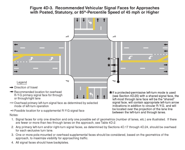
Figure 4D-3. Recommended Vehicular Signal Faces for Approaches with Posted, Statutory, or 85th-Percentile Speed of 45 mph or Higher
This figure shows locations for recommended vehicular signal faces for approaches with posted, statutory, or 85th-percentile speed of 45 mph or higher.
A legend shows the following symbols:
- A black arrow denoting direction of travel
- A triangular black arrow as a recommended location for overhead R-Y-G primary signal face for through or through/right lane
- A dotted triangular arrow as an overhead primary left-turn signal face as determined by selected mode of left-turn operation
- A solid triangular arrow as a possible location for a supplemental R-Y-G signal face
The following notes are included:
- Signal faces for only one direction and only one possible set of geometrics (number of lanes, etc.) are illustrated. If there are fewer or more than two through lanes on the approach, see Table 4D-2.
- Any primary left-turn and/or right-turn signal faces, as determined by Sections 4D.17 through 4D.24, should be overhead for each exclusive turn lane.
- One or more pole-mounted or overhead supplemental faces should be considered, based on the geometrics of the approach, to maximize visibility for approaching traffic.
- All signal faces should have backplates.
This figure shows the intersection of a five-lane horizontal roadway with a five-lane vertical roadway. Arrows show that the direction of travel is two lanes eastbound and two lanes westbound with opposing center turn lanes on the horizontal roadway, and two lanes northbound and two lanes southbound with opposing center turn lanes on the vertical roadway.
Both roadways are composed of two through lanes in each direction and a center left turn lane. On both roadways, the through lanes are divided from each other by a broken white line. The left turn lane is divided from the same direction through lanes by a solid white line, with an optional dotted white line extension in advance of the solid white line. The beginning of the left turn lane is shown by a solid double yellow line that angles from the broken white line to the solid double yellow line that separates the turn lane from the oncoming lanes. White left-turn arrows are marked in the turn lanes. A solid white stop line is marked across all approach lanes at the intersection. Two parallel solid white lines denoting crosswalks are shown on each side of the intersection on each roadway.
A vertical line denoting an overhead signal arm is shown at the southeast corner, extending over the eastbound lanes just beyond the crosswalk. Symbols for three signals are shown over the eastbound center left-turn lane and two through lanes. They are shown as a dotted white triangular arrow over the westbound center lane and facing eastbound traffic, a black triangular arrow over the westbound right through lane and facing the eastbound left through lane, and a black triangular arrow over the westbound left through lane and facing the eastbound right through lane. A note for the first two signal symbols states: "If a protected-permissive left-turn mode is used (see Section 4D.20) with a shared signal face, the left-most through lane face will be the "shared" signal face, will contain appropriate left-turn arrow indications in addition to circular R-Y-G, and will be located over the projection of the lane line between the left-turn and through lanes."
A solid white triangular arrow is shown on each corner, denoting a possible location for a supplemental red-yellow-green signal.
