|
|
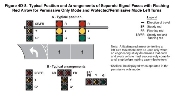
2009 Edition Part 4 Figure 4D-8. Typical Position and Arrangements of Separate Signal Faces with Flashing Red Arrow for Permissive Only Mode and Protected/Permissive Mode Left Turns

Figure 4D-8. Typical Position and Arrangements of Separate Signal Faces with Flashing Red Arrow for Permissive Only Mode and Protected/Permissive Mode Left Turns
This figure shows the typical position and arrangements of separate signal faces with flashing red arrow for permissive only mode and protected/permissive mode left turns. A legend shows a black arrow indicating the direction of travel on the roadway.
A note states: "A flashing red arrow controlling a left-turn movement may be used only when an engineering study determines that each and every vehicle must successively come to a full stop before making a permissive turn."
The figure shows two types of examples. The first example is labeled "A – Typical Position." It shows three signals aligned horizontally on a horizontal pole over a vertical segment of three lanes of a roadway. A white left-turn arrow is shown marked in the left lane to the left of white chevron markings for a theoretical gore, and upward-pointing black arrows in the center and right lanes denote the direction of travel as straight through. The left signal is shown above the left lane as a vertical arrangement of a left-turn steady red and flashing red arrow, left-turn yellow arrow, and left-turn green arrow. A note states that the left-turn green arrow "shall not be displayed when operated in the permissive only mode." The middle signal is shown above the center lane as a vertical arrangement of circular red, circular yellow, and circular green signal indications. The right signal is shown above the right lane as a vertical arrangement of a circular red, circular yellow, and circular green signal indications.
The second type of example is labeled "B – Typical Arrangements." It shows three arrangements. The left arrangement shows a vertical arrangement of three signal indications – left-turn steady red and flashing red arrow, left-turn yellow arrow, and left-turn green arrow. The middle arrangement shows the same three signal indications arranged vertically except separate left-turn steady red and flashing red arrows are shown arranged horizontally, centered above the left-turn yellow and green arrow signal indications. The right arrangement shows the left-turn steady red and flashing red arrow, left-turn yellow arrow, and left-turn green arrow signal indications arranged horizontally. A note pertaining to all three arrangements states that the left-turn green arrow signal indications "shall not be displayed when operated in the permissive only mode."
