
|
|
2009 Edition Part 4 Figure 4D-20. Signal Indications for Approaches with a Shared Left-Turn/Right-Turn Lane and No Through Movement (Sheet 3 of 3)
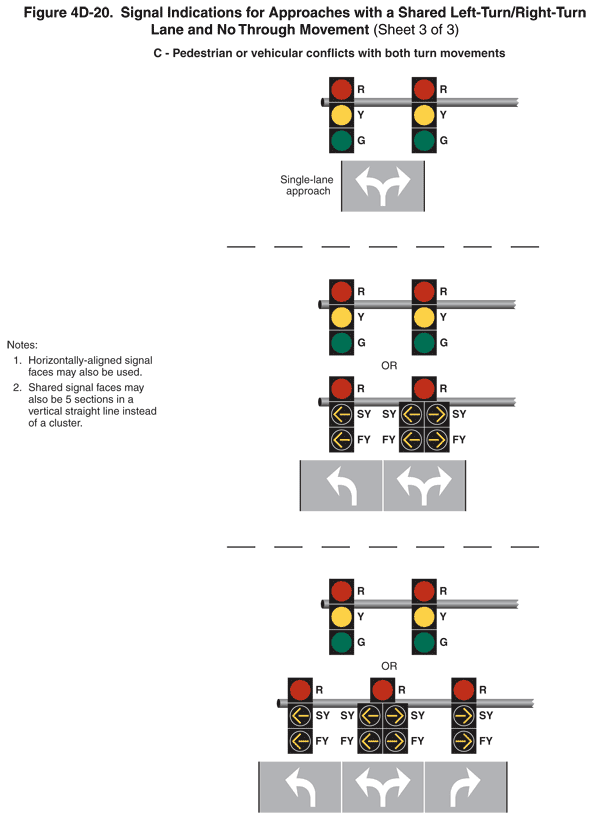
Figure 4D-20. Signal Indications for Approaches with a Shared Left-Turn/Right-Turn Lane and No Through Movement (Sheet 3 of 3)
This figure shows signal indications for approaches with a shared left-turn/right-turn lane and no through movement. The figure is composed of three sheets showing nine examples.
Sheet 3 shows three examples labeled "C - Pedestrian or Vehicular Conflict with Both Turn Movements."
Two notes state: "1. Horizontally-aligned signal faces may also be used. 2. Shared signal faces may also be 5 sections in a vertical straight line instead of a cluster."
The first example shows two signals aligned horizontally on a horizontal pole centered over a vertical segment of a single-lane approach on a roadway. A combined left-turn/right-turn white arrow is shown marked on the pavement. The left signal is shown as a vertical arrangement of circular red, circular yellow, and circular green signal indications. The right signal is shown as the same signal.
The second example shows two signals aligned horizontally on a horizontal pole over a vertical segment of two lanes of a roadway. A left-turn white arrow is shown marked in the left lane, and a combined left-turn/right-turn white arrow is shown marked in the right lane. The left signal is shown above the left lane as a vertical arrangement of circular red, circular yellow, and circular green signal indications. The right signal is shown above the right lane as the same signal. Below these signals, the word "OR" is shown and another set of signals. The left signal is shown above the left lane as a vertical arrangement of circular red, left-turn steady yellow arrow, and left-turn flashing yellow arrow signal indications. The right signal is shown above the right lane as a vertical arrangement of a circular red signal indication centered above a left-turn steady yellow arrow signal indication to the left of a right-turn steady yellow arrow signal indication. These are shown above a left-turn flashing yellow arrow signal indication to the left of a right-turn flashing yellow arrow signal indication.
The third example shows two signals aligned horizontally on a horizontal pole over a vertical segment of three lanes of a roadway. A left-turn white arrow is shown marked in the left lane, a combined left-turn/right-turn white arrow is shown marked in the middle lane, and a right-turn white arrow is shown marked in the right lane. The left signal is shown above the solid white line separating the left and center lanes and is shown as a vertical arrangement of circular red, circular yellow, and circular green signal indications. The right signal is shown above the solid white line separating the middle and right lanes and is shown as the same signal. Below these signals, the word "OR" is shown and another set of signals. The left signal is shown above the left lane as a vertical arrangement of circular red, left-turn steady yellow arrow, and left-turn flashing yellow arrow signal indications. The middle signal is shown above the center lane as a vertical arrangement of a circular red signal indication centered above a left-turn steady yellow arrow signal indication to the left of a right-turn steady yellow arrow signal indication. These are shown above a left-turn flashing yellow arrow signal indication to the left of a right-turn flashing yellow arrow signal indication. The right signal is shown above the right lane as a vertical arrangement of circular red, right-turn steady yellow arrow, and right-turn flashing yellow arrow signal indications.