|
|
2009 Edition Part 8 Figure 8C-1. Composite Drawing of Active Traffic Control Devices for Grade Crossings Showing Clearances

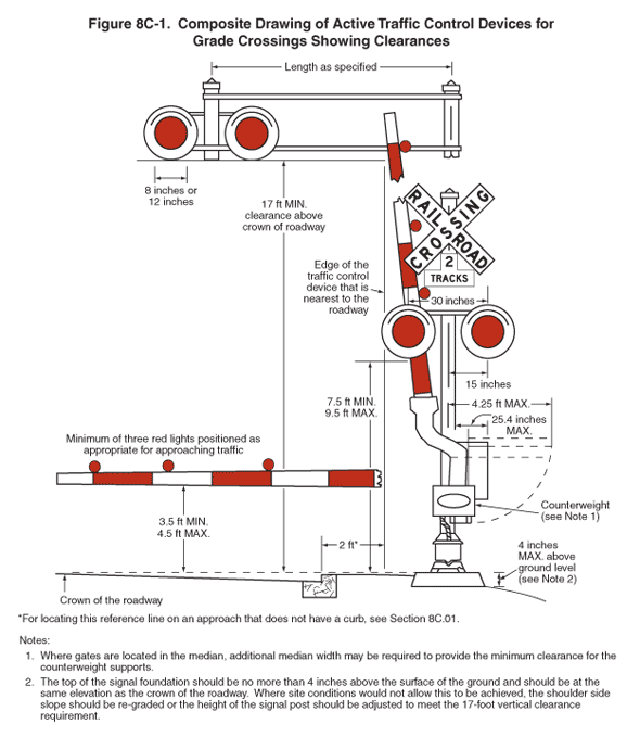
Figure 8C-1. Composite Drawing of Active Traffic Control Devices for Grade Crossings Showing Clearances
This figure shows a composite drawing of active traffic control devices for grade crossings showing clearances. It illustrates the location and clearance dimensions of a traffic control assembly with signal lights and a gate at an at-grade crossing.
The figure shows a post-mounted flashing-light signal with two red lights shown mounted in a horizontal line, two red flashing-light signals shown mounted on an overhead structure, and a red and white vertically striped automatic gate assembly with three red lights. The gate is also shown in the horizontal position to the left of the post, extending across the pavement. A white Railroad Crossing crossbuck sign and inverted T-shaped sign with the words "2 TRACKS" are also shown mounted on the post above the post-mounted lights.
On the overhead light structure, the distance from the center of the mounting post to the center of the flashing-light signal support is shown as a length as specified. The distance from the crown of the roadway to the bottom of the background disks behind the signal light lenses is shown as a dimensioned distance of 17 ft MIN. clearance above crown of roadway. The diameter of each lens is shown as a dimension of 8 inches to 12 inches.
The location of the traffic control assembly when the gate is in an upright position is shown as a dimensioned distance of 2 ft from the edge of the background of the signal light lens or part nearest the roadway to the edge of the roadway. A note states: "For locating this reference line on an approach that does not have a curb, see Section 8C.01."
The base of the post assembly is shown as a dimension of 4 inches MAX above ground level. A note states: "The top of the signal foundation should be no more than 4 inches above the surface of the ground and should be at the same elevation as the crown of the roadway. Where site conditions would not allow this to be achieved, the shoulder side slope should be re-graded or the height of the signal post should be adjusted to meet the 17-foot vertical clearance requirement." The distance from the center of the mounting post to the counterweight end of the gate is shown as a dimensioned distance of 4.25 ft MAX. The distance from the outside edge of the mounting post to the top edge of the counterweight of the gate is shown as a dimensioned distance of 25.4 inches MAX. A note for the counterweight of the gate states "Where gates are located in the median, additional median width may be required to provide the minimum clearance for the counterweight supports." The distance from the crown of the roadway to the bottom of the overhead lights is shown as a dimensioned distance of 7.5 ft MIN. to 9.5 ft MAX.
Two red signal lights with background disks behind the lenses are shown mounted on the traffic control post. The distance between the centers of the two lights is shown as a dimensioned distance of 30 inches. The distance from the center of the mounting post to the center of each lens is shown as a dimensioned distance of 15 inches.
A red and white gate is shown attached to the post. The gate arm is shown with alternating red and white retroreflectorized stripes. The gate arm is shown with three red lights on the top edge with a note that states "Minimum of three red lights positioned as appropriate for approaching traffic." The distance from the crown of the roadway to the bottom of the gate when horizontal is shown as a dimensioned distance of 3.5 ft MIN. to 4.5 ft MAX.
