
|
|
2009 Edition Part 8 Figure 8C-2. Example of Location Plan for Flashing-Light Signals and Four-Quadrant Gates
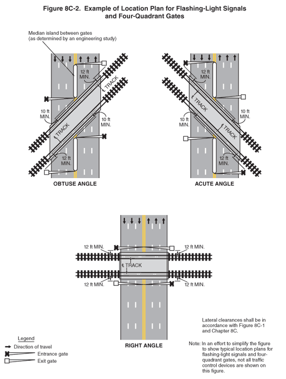
Figure 8C-2. Example of Location Plan for Flashing-Light Signals and Four-Quadrant Gates
This figure illustrates three examples of railroad tracks crossing roadways with four-quadrant gates and signals.
A note states: "In an effort to simplify the figure to show typical location plans for flashing-light signals and four-quadrant gates, not all traffic control devices are shown on this figure." A legend shows a black arrow indicating the direction of travel on the roadway, a white square indicating an entrance gate, and a black "X" indicating an exit gate.
The first example shows two railroad tracks crossing a six-lane roadway at an obtuse angle, with the tracks shown running from the southwest on the left to the northeast on the right. Arrows show the direction of travel on the roadway is three lanes in each direction. On each side of the railroad tracks, two gates are shown: one that extends across the three right lanes (the entrance gate) and one that extends across the three left lanes (the exit gate). On each side of the railroad tracks, a median island is shown placed between the two gates as determined by an engineering study. On each side of the tracks, the dimensioned distance from the center line of the near track to the entrance gate across the right (approach) lanes is shown as 10 ft MIN. The dimensioned distance from the center line of the far track to the exit gate in the left (exit) lanes is shown as 12 ft MIN.
The second example shows the same example of railroad tracks crossing a roadway as the first example, except these tracks are shown at an acute angle, with the tracks shown running from the northwest on the left to the southeast on the right.
The third example shows two railroad tracks crossing a six-lane roadway at a right angle. Arrows show the direction of travel is three lanes in each direction. On each side of the railroad tracks, two gates are shown: an entrance gate that extends across the three right (approach) lanes and an exit gate that extends across the three left (exit) lanes. On each side of the tracks, the dimensioned distance from the center line of the near track to each gate is shown as 12 ft MIN.
A note states "Lateral clearances shall be in accordance with Figure 8C-1 and Chapter 8C."