
|
|
2009 Edition Part 8 Figure 8C-6. Example of a Separate Pedestrian Gate
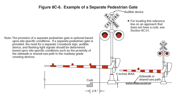
Figure 8C-6. Example of a Separate Pedestrian Gate
This figure illustrates an example of a separate pedestrian gate placement.
The figure shows two signal assemblies next to each other. The assembly on the left is larger.
A note states: "The provision of a separate pedestrian gate is optional based upon site-specific conditions. If a separate pedestrian gate is provided, the need for a separate Crossbuck sign, audible device, and flashing-light signals should be determined based upon site-specific conditions such as the proximity of the sidewalk or shared-use path to the roadway grade crossing devices."
The larger figure shows a post-mounted flashing-light signal with two red lights shown mounted in a horizontal line and a red and white vertically striped automatic gate assembly. A rounded-top audible device is shown mounted on top of the post. A white crossbuck sign with the words "RAILROAD CROSSING" in black is shown mounted on the post below the audible device and above the post-mounted lights.
The automatic gate is shown in the horizontal position to the left of the post, extending across the curb and roadway. The automatic gate arm is shown with vertical alternating red and white stripes and three red lights along the top edge.
The base of the post assembly is shown as a dimensioned thickness of 4 inches MAX. The distance from the outside edge of the post-mounted light to the beginning of the roadway beyond the curb is shown as a dimension of 2 ft with the note: "For locating this reference line on an approach that does not have a curb, see Section 8C.01."
The smaller figure shows the same signal assembly but with only one red light along the top edge of the gate arm. The gate is shown extending over a sidewalk or shared-use path.