|
|
2009 Edition Part 6 Figure 6H-36. Lane Shift on a Freeway (TA-36)

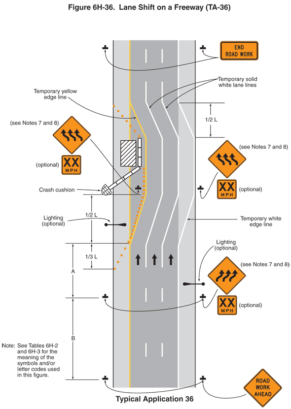
Figure 6H-36. Lane Shift on a Freeway (TA-36)
This figure shows an example of lane shift on a freeway. A legend under the illustration states that this is Typical Application 36. A note states "See Tables 6H-2 and 6H-3 for the meaning of the symbols and/or letter codes used in this figure."
The figure shows one side of a vertical freeway with three lanes. Upward-pointing black arrows in each lane denote the direction of traffic. The lanes are shown separated from each other by broken white lines. Left and right shoulders are shown outside the lanes. The left shoulder is shown separated from the left lane by a solid yellow line. The right shoulder is shown separated from the right lane by a solid white line.
At the bottom of the figure and outside the left and right shoulders, two black inverted "Ts" are shown denoting signs. The signs are shown as diamond-shaped orange signs with black borders and the words "ROAD WORK AHEAD" in black. These signs are shown at a dimensioned distance B in advance of sign assemblies outside the left and right shoulders. The sign assemblies are composed of a diamond-shaped orange sign with a black border and three upward-pointing arrows that slant diagonally up and to the right and then straighten to a vertical direction, denoting a reverse curve. A note states "see Notes 7 and 8." This sign is shown above a square orange plaque with a black border and the words "XX MPH" in black and is labeled optional. Just beyond the sign assembly on the outside of the right shoulder, a horizontal black oar-shaped symbol, labeled Lighting (optional), is shown extending across the shoulder.
One-third from the bottom of the figure, a series of orange squares denoting channelizing devices is shown beginning and tapering from the left edge of the left shoulder to the left edge of the solid yellow line between the shoulder and the left lane for a dimensioned distance 1/3 L. From this point, a solid single yellow line is shown, labeled temporary yellow edge line. The temporary yellow edge line is shown extending from the solid yellow edge line and angling upward toward the right at a dimensioned distance 1/2 L, shifting the left travel lane to the right one lane. From there, the temporary yellow edge line is shown extending vertically past a series of closely spaced white rectangles, representing temporary barriers, and a vertical rectangle with diagonal black stripes, representing a work space. The temporary yellow edge line then is shown angling upward to the left for a dimensioned distance 1/2 L to rejoin the solid yellow edge line. Two solid single white lines labeled temporary solid white lane lines and a solid white line labeled temporary white edge line are shown following exactly the same pattern. They are shown as extensions of the two normal broken white lane lines and the white edge line and are shown shifting the normal middle and right lanes one lane width to the right.
At a dimensioned distance 1/3 L above the channelizing device closest to the left edge of the shoulder, a series of closely spaced channelizing devices is shown continuing the row of channelizing devices that taper the shoulder by extending upward from the solid yellow edge line at an angle to the right edge of the left lane. The channelizing devices are shown on the left side of the temporary yellow edge line and continuing along that line to the beginning of the work space. Just beyond the end of the shoulder taper and outside of the left lane, another horizontal black oar-shaped symbol, labeled Lighting (optional), is shown extending across the shoulder.
At a dimensioned distance 1/2 L, which is the end of the first lane shift, a series of temporary barriers is shown. A symbol for a crash cushion, identified by a half oval outlined in black with a cross hatch pattern, is shown at the front of the first barrier section. The crash cushion is shown just outside the left shoulder. The temporary barrier is shown angling upward from the crash cushion across the shoulder and about halfway across the closed left traffic lane. From this point, the barrier is shown continuing straight to the end of the work space. The work space is shown straddling the left shoulder and the closed left travel lane. From the end of the work space, a series of channelizing devices is shown tapering to the left to the left edge of the shoulder, which is opposite the point where the lane shift to the left is shown ending.
Directly to the right of the crash cushion in the closed left lane and also in the area outside of the right lane, a sign assembly is shown. These signs are shown as the same as the signs described for the first lane shift to the right but with arrows shifting to the left. A note states "see Notes 7 and 8." Beyond the end of the left lane shift and at the top of the figure, two horizontal rectangular orange signs with black borders and the words "END ROAD WORK" in black are shown outside the left and right shoulders.
