
Chapter 2E. Guide Signs—Freeways and Expressways
Section 2E.31 Next Exit Supplemental Signs
Option:
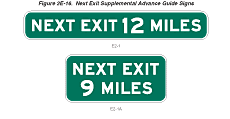
Where the distance to the next interchange is unusually long, Next
Exit supplemental signs may be installed to inform road users of
the distance to the next interchange (see Figure 2E-16).
Figure 2E-16 Next Exit Supplemental Advance Guide Signs
Guidance:
The Next Exit supplemental sign should not be used unless the distance
between successive interchanges is more than 8 km (5 mi).
Standard:
The Next Exit supplemental sign shall carry the legend NEXT EXIT
X km (X MILES). If the Next Exit supplemental sign is used, it shall
be placed below the Advance Guide sign nearest the interchange.
It shall be mounted so as to not adversely affect the breakaway
feature of the sign support structure.
Option:
The legend for the Next Exit supplemental sign may be displayed
in either one or two lines. The one-line message is the more desirable
choice unless the message causes the sign to have a horizontal dimension
greater than that of the Advance Guide sign.
Section 2E.32 Other Supplemental Guide Signs
Support:
Supplemental Guide signs can be used to provide information regarding
destinations accessible from an interchange, other than places shown
on the standard interchange signing. However, such Supplemental
Guide signing can reduce the effectiveness of other more important
guide signing because of the possibility of overloading the road
user's capacity to receive visual messages and make appropriate
decisions. "The AASHTO Guidelines for the Selection of Supplemental
Guide Signs for Traffic Generators Adjacent to Freeways" is incorporated
by reference in this section (see Addresses
for AASHTO's address).
Guidance:
No more than one Supplemental Guide sign should be used on each
interchange approach.
A Supplemental Guide sign (see Figure 2E-17) should not list more than two destinations. Destination names should be followed by the interchange number (and suffix), or if interchanges are not numbered, by the legend NEXT RIGHT or SECOND RIGHT or both, as appropriate. The Supplemental Guide sign should be installed as an independent guide sign assembly.
Figure 2E-17 Supplemental Guide Signs for Multi-exit Interchanges
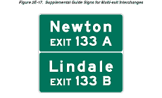
Where two or more Advance Guide signs are used, the Supplemental Guide sign should be installed approximately midway between two of the Advance Guide signs. If only one Advance Guide sign is used, the Supplemental Guide sign should follow it by at least 245 m (800 feet). If the interchanges are numbered, the interchange number should be used for the action message.
States and other agencies should adopt an appropriate policy for installing supplemental signs using "The AASHTO Guidelines for the Selection of Supplemental Guide Signs for Traffic Generators Adjacent to Freeways." In developing policies for such signing, such items as population, amount of traffic generated, distance from the route, and the significance of the destination should be taken into account.
Standard:
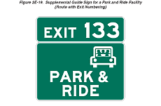
Guide signs directing drivers to park and ride facilities shall
be considered as Supplemental Guide signs (see Figures 2E-18 and
2E-19).
Figure 2E-18 Supplemental Guide Sign for a Park and Ride Facility (Route without Exit Numbering)
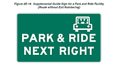
Figure 2E-19 Supplemental Guide Sign for a Park and Ride Facility (Route with Exit Numbering)
Section 2E.33 Exit Direction Signs
Support:
The Exit Direction sign repeats the route and destination information
that was shown on the Advance Guide sign(s) for the next exit, and
thereby assures road users of the destination served and indicates
whether they exit to the right or the left for that destination.
Standard:
Exit Direction signs (see Figure 2E-20) shall be used at major and
intermediate interchanges. Population figures or other similar information
shall not be used on Exit Direction signs.
Figure 2E-20 Interchange Exit Direction Sign

Guidance:
Exit Direction signs should be used at minor interchanges.
Ground-mounted Exit Direction signs should be installed at the beginning of the deceleration lane. If there is less than 90 m (300 ft) from the beginning of the deceleration lane to the theoretical gore (see Figure 3B-8), the Exit Direction sign should be installed overhead over the exiting lane in the vicinity of the theoretical gore.
Standard:
Where a through lane is being terminated (dropped) at an exit, the
Exit Direction sign shall be placed overhead at the theoretical
gore (see Figures 2E-8
and 2E-10).
The following provisions shall govern the design and application of the overhead Exit Direction sign:
- The sign shall carry the exit number (if used), the route number, cardinal direction, and destination with an appropriate upward slanting arrow (see Figure 2E-20).
- The message EXIT ONLY in black on a yellow panel shall be used on the overhead Exit Direction sign to advise road users of a lane drop situation. The sign shall conform to the provisions of Section 2E.20.
- Diagrammatic signs shall not be employed at the exit direction location.
Guidance:
Exit number plaques should be located toward the left edge of the
sign for a left exit and toward the right edge for right exits.
Option:
In some cases, principally in urban areas, where restricted sight
distance because of structures or unusual alignment make it impossible
to locate the Exit Direction sign without violating the required
minimum spacing (see Section 2E.30)
between major guide signs, Interchange Sequence signs (see Section
2E.37) may be substituted for an Advance Guide sign.
Guidance:
At multi-exit interchanges, the Exit Direction sign should be located
directly over the exiting lane for the first exit. At the same location,
and normally over the right through lane, an Advance Guide sign
for the second exit should be located. Only for those conditions
where the through movement is not evident should a confirmatory
message (Pull-Through sign as shown in Figure
2E-2) be used over the left lane(s) to guide road users traveling
through an interchange. In the interest of sign spreading, three
signs on one structure should not be used. When the freeway or expressway
is on an overpass, the Exit Direction sign should be installed on
an overhead support over the exit lane in advance of the gore point.
Option:
If the second exit is beyond an underpass, the Exit Direction sign
may be mounted on the face of the overhead structure.
Section 2E.34 Exit Gore Signs
Support:
The Exit Gore sign in the gore indicates the exiting point or the
place of departure from the main roadway. Consistent application
of this sign at each exit is important.
Standard:
The gore shall be defined as the area located between the main roadway
and the ramp just beyond where the ramp branches from the main roadway.
The Exit Gore sign shall be located in the gore and shall carry
the word EXIT or EXIT XX (if interchange numbering is used) and
an appropriate upward slanting arrow (see Figure 2E-21). Breakaway
or yielding supports shall be used.
Figure 2E-21 Exit Gore Signs
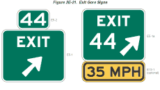
Guidance:
The arrow should be aligned to approximate the angle of departure.
Each gore should be treated similarly, whether the interchange has
one exit roadway or multiple exits.
Option:
Where extra emphasis of an especially low advisory ramp speed is
needed, an E13-1 panel indicating the advisory speed may be mounted
below the Exit Gore sign (see Figure 2E-21) to supplement, but not
to replace, the exit or ramp advisory speed warning signs.
Section 2E.35 Post-Interchange Signs
Guidance:
If space between interchanges permits, as in rural areas, and where
undue repetition of messages will not occur, a fixed sequence of
signs should be displayed beginning 150 m (500 ft) beyond the end
of the acceleration lane. At this point a Route sign assembly should
be installed followed by a Speed Limit sign and a Distance sign,
each at a spacing of 300 m (1,000 ft).
If space between interchanges does not permit placement of these three post-interchange signs without encroaching on or overlapping the Advance Guide signs necessary for the next interchange, or in rural areas where the interchanging traffic is primarily local, one or more of the post-interchange signs should be omitted.
Option:
Usually the Distance sign will be of less importance than the other
two signs and may be omitted, especially if Interchange Sequence
signs are used. If the sign for through traffic on an overhead assembly
already contains the route sign, the post-interchange route sign
assembly may also be omitted.
Section 2E.36 Distance Signs
Standard:
If used, the post-interchange Distance sign shall consist of a two-
or three-line sign carrying the names of significant destination
points and the distances to those points. The top line of the sign
shall identify the next meaningful interchange with the name of
the community near or through which the route passes, or if there
is no community, the route number or name of the intersected highway
(see Figure 2E-22).
Support:
The minimum sizes of the route shields identifying a significant
destination point are prescribed in Tables 2E-1 though 2E-4.
Option:
The test identification of a route may be shown instead of a route
shield, such as "US XX", "State Route XX", or
"County Route X".
Figure 2E-22 Post-Interchange Distance Sign
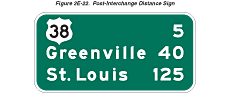
Guidance:
If a second line is used, it should be reserved for communities
of general interest that are located on or immediately adjacent
to the route or for major traffic generators along the route.
Option:
The choice of names for the second line, if it is used, may be varied
on successive Distance signs to give road users maximum information
concerning communities served by the route.
Standard:
The third, or bottom line, shall contain the name and distance to
a control city (if any) that has national significance for travelers
using the route.
Guidance:
Distances to the same destinations should not be shown more frequently
than at 8 km (5 mi) intervals. The distances displayed on these
signs should be the actual distance to the destination points and
not to the exit from the freeway or expressway.
Section 2E.37 Interchange Sequence Signs
Guidance:
If there is less than 245 m (800 ft) between interchanges, Interchange
Sequence signs should be used instead of the Advance Guide signs
for the affected interchanges. If used, Interchange Sequence signs
should be used over the entire length of a route in an urban area.
They should not be used on a single interchange basis.
Option:
If interchanges are closely spaced, particularly through large urban
areas, so that guide signs cannot be adequately spaced, Interchange
Sequence signs identifying the next two or three interchanges may
be used.
Support:
Interchange Sequence signs are generally supplemental to Advance
Guide signs. Signing of this type is illustrated in Figures 2E-23
and 2E-24, and is compatible with the sign spreading concept.
These signs are installed in a series and display the next two or three interchanges by name or route number with distances to the nearest 400 m or 1/4 mile.
Figure 2E-23 Signing of Closely Spaced Interchanges Using Interchange Sequence Signs
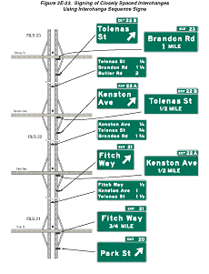
Figure 2E-24 Interchange Sequence Sign
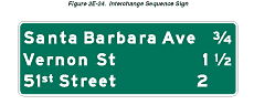
Standard:
If used, the first sign in the series shall be located in advance
of the first Advance Guide sign for the first interchange.
Where the exit direction is to the left, interchange names or route numbers shown on such signs shall be followed by the legend LEFT or LEFT EXIT in black letters on a yellow rectangular background.
Interchange Sequence signs shall not be substituted for Exit Direction signs.
Guidance:
Interchange Sequence signs should be located in the median. After
the first of the series, Interchange Sequence signs should be placed
approximately midway between interchanges.
Standard:
Interchange Sequence signs located in the median shall be installed
at overhead sign height.
Option:
Interchange numbers may be shown to the left of the interchange
name or route number.
Section 2E.38 Community Interchanges Identification Signs
Support:
For suburban or rural communities served by two or three interchanges,
Community Interchanges Identification signs are useful (see Figure
2E-25).
Figure 2E-25 Community Interchanges Identification Sign
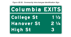
Guidance:
In these cases, the name of the community followed by the word EXITS
should be shown on the top line; the lines below should display
the destination, road name or route number, and the corresponding
distances to the nearest 400 m or 1/4 mile.
The sign should be located in advance of the first Advance Guide sign for the first interchange within the community.
Option:
If interchanges are not conveniently identifiable or if there are
more than three interchanges to be identified, the NEXT X EXITS
sign (see Section 2E.39) may
be used.
Section 2E.39 NEXT X EXITS Sign
Support:
Many freeways or expressways pass through historical or recreational
regions, or urban areas served by a succession of several interchanges.
Option:
Such regions or areas may be indicated by a NEXT X EXITS sign (see
Figure 2E-26) located in advance of the Advance Guide sign or signs
for the first interchange.
Figure 2E-26 NEXT EXITS Sign

Guidance:
The sign legend should identify the region or area followed by the
words NEXT X EXITS.
Section 2E.40 Signing by Type of Interchange
Support:
Road users need signs to help identify the location of the exit,
as well as to obtain route, direction, and destination information
for specific exit ramps. Figures 2E-27
through 2E-32
show examples of guide signs for common types of interchanges. The
interchange layouts shown in most of the figures illustrate only
the major guide signs for one direction of traffic on the through
road and on the crossroad.
Standard:
Interchange guide signing shall be consistent for each type of interchange
along a route.
Guidance:
The signing layout for all interchanges having only one exit ramp
in the direction of travel should be similar, regardless of the
interchange type (see Figures 2E-8,
2E-10,
and Figures 2E-27
through 2E-32).
For the sake of uniform application, the significant features of
the signing plan for each of the more frequent kinds of interchanges
(illustrated in Figures 2E-27 through 2E-32) should be followed
as closely as possible. Even when unusual geometric features exist,
variations in signing layout should be held to a minimum.
Section 2E.41 Freeway-to-Freeway Interchange
Support:
Freeway-to-freeway interchanges are major decision points where
the effect of taking a wrong ramp cannot be easily corrected. Reversing
direction on the connecting freeway or reentering to continue on
the intended course is usually not possible. Figure 2E-27 shows
examples of guide signs at a freeway-to-freeway interchange.
Figure 2E-27 Examples of Freeway-to-Freeway Interchange Guide Signs
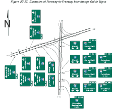
Guidance:
The sign messages should contain only the route shield, cardinal
direction, and the name of the next control city on the route. Arrows
should point as indicated in Section
2D.08, unless a diagrammatic representation of the interchange
layout requires otherwise.
At splits where the off-route movement is to the left or where there is an optional lane split, expectancy problems usually result, and diagrammatic signs should be used at the Advance Guide sign location. Diagrammatic signs (see Section 2E.19) also should be used at the Advance Guide sign locations for interchanges where two-lane exits with an optional lane carry the through route on the exiting lanes.
Standard:
Overhead signs shall be used at a distance of 2 km or 1 mile and
at the theoretical gore of each connecting ramp. When diagrammatic
signs are used, they shall conform to the provisions of Section
2E.19.
Option:
Overhead signs may also be used at the 1 km or 0.5 mile and 4 km
or 2 mile points.
The arrow and/or the name of the control city may be omitted on signs that indicate the straight-ahead continuation of a route.
An Exit Speed sign may be used where an engineering study shows that it is necessary to display a speed reduction message for ramp signing (see Section 2C.36).
Section 2E.42 Cloverleaf Interchange
Support:
A cloverleaf interchange has two exits for each direction of travel.
The exits are closely spaced and have common Advance Guide signs.
Examples of guide signs for cloverleaf interchanges are shown in
Figure 2E-28.
Figure 2E-28 Examples of Guide Signs for Full Cloverleaf Interchange
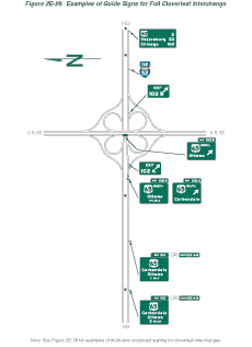
Guidance:
The Advance Guide signs should include two place names, one corresponding
to each exit ramp, with the name of the place served by the first
exit on the upper line.
Standard:
An Overhead Guide sign shall be placed at the theoretical gore point
of the first exit ramp, with an upward slanting arrow on the exit
direction sign for that exit and the message XX km (XX MILE) on
the Advance Guide sign for the second exit, as shown in Figure 2E-28.
The second exit shall be indicated by an overhead Exit Direction
sign over the auxiliary lane. An Exit sign shall also be used at
each gore (see Section 2E.34).
Interchanges with more than one exit from the main line shall be numbered as described in Section 2E.28 with an appropriate suffix.
Diagrammatic signs shall not be used for cloverleaf interchanges.
Guidance:
As shown in Figure 2E-28, the overhead Exit Direction sign for the
second exit should be mounted on the structure if the mainline passes
under the crossroad and the exit roadway is located beyond the structure.
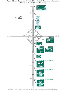
Section 2E.43 Cloverleaf Interchange with Collector-Distributor Roadways
Support:
Examples of guide signs for full cloverleaf interchanges with collector-distributor
roadways are shown in Figure 2E-29.
Guidance:
Signing on the collector-distributor roadways should be the same
as the signing on the mainline of a cloverleaf interchange.
Standard:
Guide signs at exits from the collector-distributor roadways shall
be overhead and located at the theoretical gore of the collector-distributor
roadway and the exit ramp.
Option:
Exits from the collector-distributor roadways may be numbered with
an appropriate suffix. The Advance Guide signs may include two place
names and their corresponding exit numbers or may use the singular
EXIT.
Figure 2E-29 Examples of Guide Signs for Full Cloverleaf Interchange with Collector-Distributor Roadways
Section 2E.44 Partial Cloverleaf Interchange
Support:
Examples of guide signs for partial cloverleaf interchanges are
shown in Figure 2E-30.
Figure 2E-30 Examples of Partial Cloverleaf Interchange Guide Signs
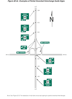
Guidance:
As shown in Figure 2E-30, the overhead Exit Direction sign should
be placed on the structure if the mainline passes under the crossroad
and the exit roadway is located beyond the structure.
Standard:
A ground-mounted Exit Gore sign shall also be installed in the ramp
gore.
Section 2E.45 Diamond Interchange
Support:
Examples of guide signs for diamond interchanges are shown in Figure
2E-31.
Figure 2E-31 Examples of Diamond Interchange Guide Signs
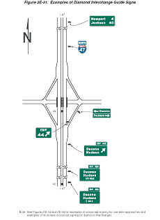
Standard:
The singular message EXIT shall be used on the Advance Guide and
Exit Direction signs. Exit numbers shall not include the cardinal
initials corresponding to the direction of the cross route.
Support:
The typical diamond interchange ramp departs from the mainline roadway
such that a speed reduction generally is not necessary in order
for a driver to reasonably safely negotiate an exit maneuver from
the mainline onto the ramp roadway.
Guidance:
When a speed reduction is not necessary, an exit speed sign should
not be used.
Option:
An Exit Speed sign may be used where an engineering study shows
that it is necessary to display a speed reduction message for ramp
signing (see Section 2C.36).
Guidance:
The Exit Speed sign should be located along the deceleration lane
or along the ramp such that it is visible to the driver far enough
in advance so that a reasonably safe slowing and exiting maneuver
can be made.
Option:
A Stop Ahead or Signal Ahead warning sign may be placed, where engineering
judgment indicates a need, along the ramp in advance of the cross
street, to give notice to the driver (see Section
2C.29).
Guidance:
When used on two-lane ramps, Stop Ahead or Signal Ahead signs should
be used in pairs with one sign on each side of the ramp.