Chapter 3B. Pavement and Curb Markings
Section 3B.01 Yellow Centerline Pavement Markings and Warrants
Standard:
Centerline pavement markings, when used, shall be the pavement markings
used to delineate the separation of traffic lanes that have opposite
directions of travel on a roadway and shall be yellow.
Option:
Centerline pavement markings may be placed at a location that is
not the geometric center of the roadway.
On roadways without continuous centerline pavement markings, short sections may be marked with centerline pavement markings to control the position of traffic at specific locations, such as around curves, over hills, on approaches to highway-railroad grade crossings, at highway-railroad grade crossings, and at bridges.
Standard:
The centerline markings on two-lane, two-way roadways shall be one
of the following as shown in Figure 3B-1:
Figure 3B-1 Examples of Two-Lane, Two-Way Marking Applications
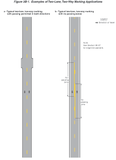
- Two-direction passing zone markings consisting of a normal broken yellow line where crossing the centerline markings for passing with care is permitted for traffic traveling in either direction;
- One-direction no-passing zone markings consisting of a normal broken yellow line and a normal solid yellow line where crossing the centerline markings for passing with care is permitted for the traffic traveling adjacent to the broken line, but is prohibited for traffic traveling adjacent to the solid line; and
- Two-direction no-passing zone markings consisting of two normal solid yellow lines where crossing the centerline markings for passing is prohibited for traffic traveling in either direction.
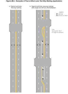
The centerline markings on undivided two-way roadways with four or more lanes for moving motor vehicle traffic always available shall be the two-direction no-passing zone markings consisting of two normal solid yellow lines as shown in Figure 3B-2.
Figure 3B-2 Examples of Four-or-More Lane, Two-Way Marking Applications
Guidance:
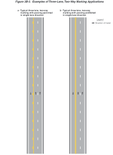
On two-way roadways with three through lanes for moving motor vehicle
traffic, two lanes should be designated for traffic in one direction
by using one- or two-direction no-passing zone markings as shown
in Figure 3B-3.
Figure 3B-3 Examples of Three-Lane, Two-Way Marking Applications
Standard:
Centerline markings shall be placed on all paved urban arterials
and collectors that have a traveled way of 6.1 m (20 ft) or more
in width and an ADT of 6,000 vehicles per day or greater. Centerline
markings shall also be placed on all paved two-way streets or highways
that have three or more lanes for moving motor vehicle traffic.
Guidance:
Centerline markings should be placed on paved urban arterials and
collectors that have a traveled way of 6.1 m (20 ft) or more in
width and an ADT of 4,000 vehicles per day or greater. Centerline
markings should also be placed on all rural arterials and collectors
that have a traveled way of 5.5 m (18 ft) or more in width and an
ADT of 3,000 vehicles per day or greater. Centerline markings should
also be placed on other traveled ways where an engineering study
indicates such a need.
Engineering judgment should be used in determining whether to place centerline markings on traveled ways that are less than 4.9 m (16 ft) wide because of the potential for traffic encroaching on the pavement edges, traffic being affected by parked vehicles, and traffic encroaching into the opposing traffic lane.
Option:
Centerline markings may be placed on other paved two-way traveled
ways that are 4.9 m (16 ft) or more in width.
If a traffic count is not available, the ADTs described in this Section may be estimates that are based on engineering judgment.
Section 3B.02 No-Passing Zone Pavement Markings and Warrants
Standard:
Where centerline markings are used, no-passing zones shall be marked
by either the one direction no-passing zone pavement markings or
the two-direction no-passing zone pavement markings described previously
and shown in Figures 3B-1 and 3B-3.
When centerline markings are used, no-passing zone markings shall be used on two-way roadways at lane reduction transitions (see Section 3B.09) and on approaches to obstructions that must be passed on the right (see Section 3B.10).
Guidance:
Where the distance between successive no-passing zones is less than
120 m (400 ft), no-passing markings should connect the zones.
Standard:
Where centerline markings are used, no-passing zone markings shall
be used on approaches to highway-rail grade crossings in conformance
with Section 8B.20.
Option:
In addition to pavement markings, no-passing zone signs (see Sections
2B.29,
2B.30,
and 2C.35)
may be used to emphasize the existence and extent of a no-passing
zone.
Support:
Section 11-307 of the "Uniform Vehicle Code (UVC) Revised" contains
further information regarding no-passing zones. The "UVC" can be
obtained from the National Committee on Uniform Traffic Laws and
Ordinances (see Addresses).
Standard:
On two-way, two- or three-lane roadways where centerline markings
are installed, no-passing zones shall be established at vertical
and horizontal curves and other locations where an engineering study
indicates that passing must be prohibited because of inadequate
sight distances or other special conditions.
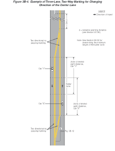
On three-lane roadways where the direction of travel in the center lane transitions from one direction to the other, a no-passing buffer zone shall be provided in the center lane as shown in Figure 3B-4. A lane transition shall be provided at each end of the buffer zone.
The buffer zone shall be a median island that is at least 15 m (50 ft) in length.
Figure 3B-4 Example of Three-Lane, Two-Way Marking for Changing Direction of the Center Lane
Guidance:
For three-lane roadways having a posted or statutory speed limit
of 70 km/h (45 mph) or greater, the lane transition taper length
should be computed by the formula L = 0.62 WS for speeds in km/h
(L = WS for speeds in mph). For roadways where the posted or statutory
speed limit is less than 70 km/h (45 mph), the formula L = WS2/155
for speeds in km/h (L = WS2/60 for speeds in mph) should
be used to compute taper length. Under both formulas, L equals the
taper length in meters (feet), W equals the width of the center
lane or offset distance in meters (feet), and S equals the 85th-percentile
speed or the posted or statutory speed limit, whichever is higher.
Standard:
The minimum lane transition taper length shall be 30 m (100 ft)
in urban areas and 60 m (200 ft) in rural areas.
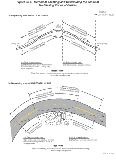
On roadways with centerline markings, no-passing zone markings shall be used at horizontal or vertical curves where the passing sight distance is less than the minimum necessary for reasonably safe passing at the 85th-percentile speed or the posted or statutory speed limit as shown in Table 3B-1. The passing sight distance on a vertical curve is the distance at which an object 1.07 m (3.5 ft) above the pavement surface can be seen from a point 1.07 m (3.5 ft) above the pavement (see Figure 3B-5). Similarly, the passing sight distance on a horizontal curve is the distance measured along the centerline (or right-hand lane line of a three-lane roadway) between two points 1.07 m (3.5 ft) above the pavement on a line tangent to the embankment or other obstruction that cuts off the view on the inside of the curve (see Figure 3B-5).
Figure 3B-5 Method of Locating and Determining the Limits of No-Passing Zones at Curves
Support:
The beginning of a no-passing zone at point "a" in Figure 3B-5 is
that point where the sight distance first becomes less than that
specified in Table 3B-1. The end of the no-passing zone at point
"b" in Figure 3B-5 is that point at which the sight distance again
becomes greater than the minimum specified.
Section 3B.03 Other Yellow Longitudinal Pavement Markings
Standard:
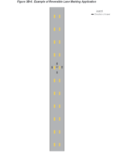
If reversible lanes are used, the lane line pavement markings on
each side of reversible lanes shall consist of a normal double broken
yellow line to delineate the edge of a lane in which the direction
of travel is reversed from time to time, such that each of these
markings serve as the centerline markings of the roadway during
some period (see Figure 3B-6).
Figure 3B-6 Example of Reversible Lane Marking Application
Signs (see Section 2B.25), lane-use control signals (see Chapter 4J), or both shall be used to supplement reversible lane pavement markings.
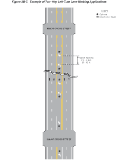
If a two-way left-turn lane that is never operated as a reversible lane is used, the lane line pavement markings on each side of the two-way left-turn lane shall consist of a normal broken yellow line and a normal solid yellow line to delineate the edges of a lane that can be used by traffic in either direction as part of a left-turn maneuver. These markings shall be placed with the broken line toward the two-way left-turn lane and the solid line toward the adjacent traffic lane as shown in Figure 3B-7.
Figure 3B-7 Example of Two-Way Left-Turn Lane Marking Applications
Option:
Pavement marking arrows may be used in conjunction with the two-way
left-turn lane markings as shown in Figure 3B-7.
Guidance:
Signs should be used in conjunction with the two-way left turn markings
(see Section 2B.24).
Standard:
If a continuous median island formed by pavement markings separating
travel in opposite directions is used, two sets of double solid
yellow lines shall be used to form the island as shown in Figures
3B-2 and 3B-4.
Other markings in the median island area shall also be yellow, except
crosswalk markings which shall be white (see Section
3B.17).
Section 3B.04 White Lane Line Pavement Markings and Warrants
Standard:
When used, lane line pavement markings delineating the separation
of traffic lanes that have the same direction of travel shall be
white.
Support:
Examples of lane line markings are shown in Figures 3B-2,
3B-3, 3B-7
through 3B-13, 3B-22,
3B-24,
and 3B-26.
Standard:
Where crossing the lane line markings with care is permitted, the
lane line markings shall consist of a normal broken white line.
Where crossing the lane line markings is discouraged, the lane line markings shall consist of a normal solid white line.
Option:
Solid white lane line markings may be used to separate through traffic
lanes from auxiliary lanes, such as uphill truck lanes, left- or
right-turn lanes, and preferential lanes. They may also be used
to separate traffic lanes approaching an intersection.
Wide solid lane line markings may be used for greater emphasis.
Standard:
Where crossing the lane line markings is prohibited, the lane line
markings shall consist of two normal solid white lines.
Lane line markings shall be used on all freeways and Interstate highways.
Guidance:
Lane line markings should be used on all roadways with two or more
adjacent traffic lanes that have the same direction of travel. Lane
line markings should also be used at congested locations where the
roadway will accommodate more traffic lanes with lane line markings
than without the markings.
Section 3B.05 Other White Longitudinal Pavement Markings
Standard:
A channelizing line shall be a wide or double solid white line.
Option:
Channelizing lines may be used to form channelizing islands where
traffic traveling in the same direction is permitted on both sides
of the island.
Standard:
Other pavement markings in the channelizing island area shall be
white.
Support:
Examples of channelizing line applications are shown in Figures
3B-8, 3B-9, and 3B-13.
Figure 3B-8 Examples of Channelizing Line Applications for Exit Ramp Markings (2 Sheets)
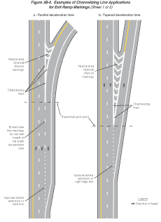
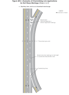
Channelizing lines at exit ramps as shown in Figure 3B-8 define the neutral area, direct exiting traffic at the proper angle for smooth divergence from the main lanes into the ramp, and reduce the probability of colliding with objects adjacent to the roadway.
Channelizing lines at entrance ramps as shown in Figure 3B-9 promote reasonably safe and efficient merging with the through traffic.
Figure 3B-9 Examples of Channelizing Line Applications for Entrance Ramp Markings
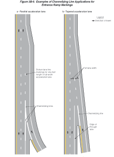
Standard:
For exit ramps, channelizing lines shall be placed along the sides
of the neutral area adjacent to the through traffic lane and the
ramp lane. With a parallel deceleration lane, a lane line shall
be extended from the beginning of the channelizing line upstream
for a distance of one-half the length of the full-width deceleration
lane as shown in Figure 3B-8.
Option:
White chevron markings may be placed in the neutral area for special
emphasis as shown in Figure 3B-8.
Guidance:
For entrance ramps, a channelizing line should be placed along the
side of the neutral area adjacent to the ramp lane.
For entrance ramps with a parallel acceleration lane, a lane line should be extended from the end of the channelizing line for a distance of one-half the length of the full-width acceleration lane as shown in Figure 3B-9.
Option:
For entrance ramps with a tapered acceleration lane, lane line markings
may be placed to extend the channelizing line, but not beyond a
point where the tapered lane meets the near side of the through
traffic lane as shown in Figure 3B-9.
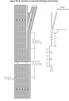
Lane drop markings as shown in Figure 3B-10 may be used in advance of lane drops at exit ramps to distinguish a lane drop from a normal exit ramp or from an auxiliary lane. The lane drop marking may consist of a wide, white dotted line with line segments 0.9 m (3 ft) in length separated by 2.7 m (9 ft) gaps.
Figure 3B-10 Example of Lane Drop Markings at Exit Ramps
Guidance:
If used, lane drop markings should begin 800 m (0.5 mi) in advance
of the theoretical gore point.
Option:
Where lane changes might cause conflicts, a wide solid white channelizing
line may extend upstream from the theoretical gore point.
Section 3B.06 Edge Line Pavement Markings
Standard:
If used, edge line pavement markings shall delineate the right or
left edges of a roadway.
Except for dotted edge line extensions (see Section 3B.08), edge line markings shall not be continued through intersections or major driveways.
If used on the roadways of divided highways or one-way streets, or on any ramp in the direction of travel, left edge line pavement markings shall consist of a normal solid yellow line to delineate the left edge of a roadway or to indicate driving or passing restrictions left of these markings.
If used, the right edge line pavement markings shall consist of a normal solid white line to delineate the right edge of the roadway.
Guidance:
Edge line markings should not be broken for minor driveways.
Support:
Edge line markings have unique value as visual references to guide
road users during adverse weather and visibility conditions.
Option:
Wide solid edge line markings may be used for greater emphasis.
Section 3B.07 Warrants for Use of Edge Lines
Standard:
Edge line markings shall be placed on paved streets or highways
with the following characteristics:
- Freeways;
- Expressways; and
- Rural arterials with a traveled way of 6.1 m (20 ft) or more in width and an ADT of 6,000 vehicles per day or greater.
Guidance:
Edge line markings should be placed on paved streets or highways
with the following characteristics:
- Rural arterials and collectors with a traveled way of 6.1 m (20 ft) or more in width and an ADT of 3,000 vehicles per day or greater.
- At other paved streets and highways where an engineering study indicates a need for edge line markings.
Edge line markings should not be placed where an engineering study or engineering judgment indicates that providing them is likely to decrease safety.
Option:
Edge line markings may be placed on streets and highways with or
without centerline markings.
Edge line markings may be excluded, based on engineering judgment, for reasons such as if the traveled way edges are delineated by curbs, parking, bicycle lanes, or other markings.
Edge line markings may be used where edge delineation is desirable to minimize unnecessary driving on paved shoulders or on refuge areas that have lesser structural pavement strength than the adjacent roadway.
Section 3B.08 Extensions Through Intersections or Interchanges
Standard:
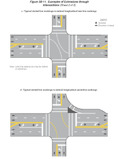
Pavement markings extended into or continued through an intersection
or interchange area shall be the same color and at least the same
width as the line markings they extend (see Figure 3B-11).
Figure 3B-11 Examples of Extensions through Intersections (2 Sheets)
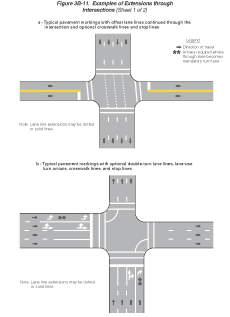
Option:
A normal line may be used to extend a wide line through an intersection.
Guidance:
Where highway design or reduced visibility conditions make it desirable
to provide control or to guide vehicles through an intersection
or interchange, such as at offset, skewed, complex, or multilegged
intersections, on curved roadways, or where multiple turn lanes
are used, dotted line markings should be used to extend longitudinal
line markings through an intersection or interchange area.
Option:
Dotted edge line extensions may be placed through intersections
or major driveways.
Guidance:
Where greater restriction is required, solid lane lines or channelizing
lines should be extended into or continued through intersections
or major driveways. However, edge lines should not be extended into
or continued through intersections or major driveways as solid lines.
A single line of equal width to one of the lines of the double line should be used to extend a double line through an intersection.
To the extent possible, pavement marking extensions through intersections should be designed in a manner that minimizes potential confusion for drivers in adjacent or opposing lanes.
Section 3B.09 Lane Reduction Transition Markings
Standard:
Where pavement markings are used, lane reduction transition markings
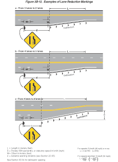
shall be used to guide traffic through transition areas where the
number of through lanes is reduced, as shown in Figure 3B-12. On
two-way roadways, no-passing zone markings shall be used to prohibit
passing in the direction of the convergence, and shall continue
through the transition area.
Figure 3B-12 Examples of Lane Reduction Markings
Guidance:
For roadways having a posted or statutory speed limit of 70 km/h
(45 mph) or greater, the transition taper length for a lane reduction
should be computed by the formula L = 0.62 WS for speeds in km/h
(L = WS for speeds in mph). For roadways where the posted or statutory
speed limit is less than 70 km/h (45 mph), the formula L = WS2/155
for speeds in km/h (L = WS2/60 for speeds in mph) should
be used to compute taper length. Under both formulas, L equals the
taper length in meters (feet), W equals the width of the offset
distance in meters (feet), and S equals the 85th-percentile speed
or the posted or statutory speed limit, whichever is higher.
Where observed speeds exceed posted or statutory speed limits, longer tapers should be used.
Option:
On new construction, where no posted or statutory speed limit is
established, the design speed may be used in the transition taper
length formula.
Guidance:
Lane line markings should be discontinued one-quarter of the distance
between the Lane Ends sign (see Section
2C.33) and the point where the transition taper begins.
Edge line markings should be installed from the location of the warning sign to beyond the beginning of the narrower roadway.
Support:
Pavement markings at lane reduction transitions supplement the standard
signs.
Section 3B.10 Approach Markings for Obstructions
Standard:
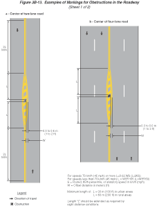
Pavement markings shall be used to guide traffic away from fixed
obstructions within a paved roadway. Approach markings for bridge
supports, refuge islands, median islands, and raised channelization
islands shall consist of a tapered line or lines extending from
the centerline or the lane line to a point 0.3 to 0.6 m (1 to 2
ft) to the right side, or to both sides, of the approach end of
the obstruction (see Figure 3B-13).
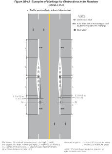
Figure 3B-13 Examples of Markings for Obstructions in the Roadway (2 Sheets)
Guidance:
For roadways having a posted or statutory speed limit of 70 km/h
(45 mph) or greater, the taper length of the tapered line markings
should be computed by the formula L = 0.62 WS for speeds in km/h
(L = WS for speeds in mph). For roadways where the posted or statutory
speed limit is less than 70 km/h (45 mph), the formula L = WS2/155
for speeds in km/h (L = WS2/60 for speeds in mph) should
be used to compute taper length. Under both formulas, L equals the
taper length in meters (feet), W equals the width of the offset
distance in meters (feet), and S equals the 85th-percentile speed
or the posted or statutory speed limit, whichever is higher.
Standard:
The minimum taper length shall be 30 m (100 ft) in urban areas and
60 m (200 ft) in rural areas.
Support:
Examples of approach markings for obstructions in the roadway are
shown in Figure 3B-13.
Option:
Where observed speeds exceed posted or statutory speed limits, longer
tapers may be used.
Standard:
If traffic is required to pass only to the right of the obstruction,
the markings shall consist of a two-direction no-passing zone marking
at least twice the length of the diagonal portion as determined
by the appropriate taper formula (see Figure 3B-13).
Option:
If traffic is required to pass only to the right of the obstruction,
yellow diagonal approach markings may be placed in the neutral area
between the no-passing zone markings as shown in Figure 3B-13. Other
markings, such as yellow delineators, raised pavement markers, and
white crosswalk pavement markings, may also be placed in the neutral
area.
Standard:
If traffic can pass either to the right or left of the obstruction,
the markings shall consist of two channelizing lines diverging from
the lane line, one to each side of the obstruction. In advance of
the point of divergence, a solid wide white line or solid double
normal white line shall be extended in place of the broken lane
line for a distance equal to the length of the diverging lines (see
Figure 3B-13).
Option:
If traffic can pass either to the right or left of the obstruction,
additional white markings may be placed in the neutral area between
the channelizing lines as shown in Figure 3B-13.
Section 3B.11 Raised Pavement Markers
Standard:
A raised pavement marker shall be a device with a height of at least
10 mm (0.4 in) mounted on or in a road surface that is intended
to be used as a positioning guide or to supplement or substitute
for pavement markings or to mark the position of a fire hydrant.
The color of raised pavement markers under both daylight and nighttime conditions shall conform to the color of the marking for which they serve as a positioning guide, or for which they supplement or substitute.
Option:
Blue raised pavement markers may be used to mark the positions of
fire hydrants.
Support:
Retroreflective and internally illuminated raised pavement markers
are available in monodirectional and bidirectional configurations.
The bidirectional marker is capable of displaying the applicable
color for each direction of travel.
Guidance:
Nonretroreflective raised pavement markers should not be used alone,
without supplemental retroreflective or internally illuminated markers,
as a substitute for other types of pavement markings.
Directional configurations should be used to maximize correct information and to minimize confusing information provided to the road user. Directional configurations also should be used to avoid confusion resulting from visibility of markers that do not apply to the road user.
The spacing of raised pavement markers used to supplement or substitute for other types of longitudinal markings should correspond with the pattern of broken lines for which the markers supplement or substitute.
Standard:
The value of N for the spacing of raised pavement markers for a
broken or dotted line shall equal the length of one line segment
plus one gap. The value of N referenced for solid lines shall equal
the N for the broken or dotted lines that might be adjacent to or
might extend the solid lines (see Sections 3B.13
and 3B.14).
Support:
Figures 9-20 through 9-22 in the "Traffic Control Devices Handbook"
(see Section 1A.11)
contain additional information regarding the spacing of raised pavement
markers on longitudinal markings.
Section 3B.12 Raised Pavement Markers as Vehicle Positioning Guides with Other Longitudinal Markings
Option:
Raised pavement markers may be used as positioning guides with longitudinal
line markings without necessarily conveying information to the road
user about passing or lane-use restrictions. In such applications,
markers may be positioned between the two lines of a one-way or
two-way no-passing zone marking or positioned in line with or immediately
adjacent to single solid or broken centerline or lane line markings.
Support:
A typical spacing for such applications is 2N, where N equals the
length of one line segment plus one gap (see Section
3B.11).
Option:
Where it is desired to alert the road user to changes in the travel
path, such as on sharp curves or on transitions that reduce the
number of lanes or that shift traffic laterally, the spacing may
be reduced to N or less.
On freeways and expressways, a spacing of 3N may be used for relatively straight and level roadway segments where engineering judgement indicates that such spacing will provide adequate delineation under wet night conditions.
Section 3B.13 Raised Pavement Markers Supplementing Other Markings
Guidance:
The use of raised pavement markers for supplementing longitudinal
line markings should conform to the following:
- Lateral Positioning
- When supplementing double line markings, pairs of raised pavement markers placed laterally in line with or immediately outside of the two lines should be used.
- When supplementing wide line markings, pairs of raised pavement markers placed laterally adjacent to each other should be used.
- Longitudinal Spacing
- When supplementing solid line markings, raised pavement markers at a spacing no greater than N (see Section 3B.11) should be used, except when supplementing left edge line markings, a spacing of no greater than N/2 should be used. Raised markers should not supplement right edge line markings.
- When supplementing broken line markings, a spacing no greater than 3N should be used. However, when supplementing broken line markings identifying reversible lanes, a spacing of no greater than N should be used.
- When supplementing dotted line markings, a spacing appropriate for the application should be used.
- When supplementing longitudinal line markings through at-grade intersections, one raised pavement marker for each short line segment should be used.
- When supplementing edge line extensions through freeway interchanges, a spacing of no greater than N should be used.
Option:
Raised pavement markers also may be used to supplement other markings
for channelizing islands or approaches to obstructions.
Section 3B.14 Raised Pavement Markers Substituting for Pavement Markings
Option:
Retroreflective or internally illuminated raised pavement markers,
or nonretroreflective raised pavement markers supplemented by retroreflective
or internally illuminated markers, may be substituted for markings
of other types.
Guidance:
If used, the pattern and color of the raised pavement markers should
simulate the pattern and color of the markings for which they substitute.
The normal spacing of raised pavement markers, when substituting for other markings, should be determined in terms of the standard length of the broken line segment.
Option:
The side of a raised pavement marker that is visible to traffic
proceeding in the wrong direction may be red.
Standard:
If raised pavement markers are used to substitute for broken line
markings, a group of three to five markers equally spaced at a distance
no greater than N/8 (see Section 3B.11)
shall be used. If N is other than 12 m (40 ft), the markers shall
be equally spaced over the line segment length (at 1/2 points for
3 markers, at 1/3 points for 4 markers, and at 1/4 points for 5
markers). At least one retroreflective or internally illuminated
marker per group shall be used or a retroreflective or internally
illuminated marker shall be installed midway in each gap between
successive groups of nonretroreflective markers.
When raised pavement markers substitute for solid lane line markings, the markers shall be equally spaced at no greater than N/4, with retroreflective or internally illuminated units at a spacing no greater than N/2.
Guidance:
Raised pavement markers should not substitute for right edge line
markings.
Standard:
When raised pavement markers substitute for dotted lines, they shall
be spaced at no greater than N/4, with not less than one raised
pavement marker per dotted line. At least one raised marker every
N shall be retroreflective or internally illuminated.
Option:
When substituting for wide lines, raised pavement markers may be
placed laterally adjacent to each other to simulate the width of
the line.
Section 3B.15 Transverse Markings
Standard:
Transverse markings, which include shoulder markings, word and symbol
markings, stop lines, yield lines, crosswalk lines, speed measurement
markings, speed hump markings, parking space markings, and others,
shall be white unless otherwise specified herein.
Guidance:
Because of the low approach angle at which pavement markings are
viewed, transverse lines should be proportioned to provide visibility
equal to that of longitudinal lines.
Standard:
Pavement marking letters, numerals, and symbols shall be installed
in accordance with the Pavement Markings chapter of the "Standard
Highway Signs" book (see Section
1A.11).
