Chapter 2D. Guide Signs—Conventional Roads
Section 2D.01 Scope of Conventional Road Guide Sign Standards
Standard:
Standards for conventional road guide signs shall apply to any road
or street other than low-volume roads (as defined in Section
5A.01), expressways, and freeways.
Section 2D.02 Application
Support:
Guide signs are essential to direct road users along streets and
highways, to inform them of intersecting routes, to direct them
to cities, towns, villages, or other important destinations, to
identify nearby rivers and streams, parks, forests, and historical
sites, and generally to give such information as will help them
along their way in the most simple, direct manner possible.
Chapter 2A addresses placement, location, and other general criteria for signs.
Section 2D.03 Color, Retroreflection, and Illumination
Support:
Requirements for illumination, retroreflection, and color are stated
under the specific headings for individual guide signs or groups
of signs. General provisions are given in Sections 2A.08,
2A.09,
and 2A.11.
Standard:
Except where otherwise specified herein for individual signs or
groups of signs, guide signs on streets and highways shall have
a white message and border on a green background. All messages,
borders, and legends shall be retroreflective and all backgrounds
shall be retroreflective or illuminated.
Support:
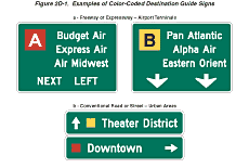
Color coding is sometimes used to help road users distinguish between
multiple potentially confusing destinations. Examples of valuable
uses of color coding include guide signs for roadways approaching
or inside an airport property with multiple terminals serving multiple
airlines, and wayfinding signs for various traffic generator destinations
within a community or area.
Standard:
Different color sign backgrounds shall not be used to provide color
coding of destinations. The color coding shall be accomplished by
the use of different colored square or rectangular panels on the
face of the guide signs.
Option:
The different colored panels may include a black or white (whichever
provides the better contrast with the panel color) letter, numeral,
or other appropriate designation to identify the airport terminal
or other destination.
Support:
Two examples of color-coded sign assemblies are shown in Figure
2D-1.
Figure 2D-1 Examples of Color-Coded Destination Guide Signs

Section 2D.04 Size of Signs
Support:
For most guide signs, the legends are so variable that a standardized
size is not appropriate. The sign size is determined primarily by
the length of the message, and the size of lettering and spacing
necessary for proper legibility. However, for signs with standardized
designs, such as route signs, it is practical to use the prescribed
sizes that are given in the "Standard Highway Signs" book (see Section
1A.11).
Option:
Reduced letter height, reduced interline spacing, and reduced edge
spacing may be used on guide signs if sign size must be limited
by factors such as lane width or vertical or lateral clearance.
Guidance:
Reduced spacing between the letters or words on a line of legend
should not be used as a means of reducing the overall size of a
guide sign, except where determined necessary by engineering judgment
to meet unusual lateral space constraints. In such cases, the legibility
distance of the sign legend should be the primary consideration
in determining whether to reduce the spacing between the letters
or the words or between the words and the sign border, or to reduce
the letter height.
When a reduction in the prescribed size is necessary, the design used should be as similar as possible to the design for the standard size.
Section 2D.05 Lettering Style
Standard:
The design of upper-case letters, lower-case letters, capital letters,
numerals, route shields, and spacing shall be as provided in the
"Standard Highway Signs" book (see Section 1A.11).
The lettering for names of places, streets, and highways on conventional road guide signs shall be a combination of lower-case letters with initial uppercase letters, or all capital letters (see Section 2A.14). When a combination of upper- and lower-case letters are used, the initial upper-case letters shall be approximately 1.33 times the "loop" height of the lower-case letters.
All other word legends on conventional road guide signs shall be in capital letters.
Section 2D.06 Size of Lettering
Support:
Sign legibility is a direct function of letter size and spacing.
Legibility distance has to be sufficient to give road users enough
time to read and comprehend the sign. Under optimum conditions,
a guide sign message can be read and understood in a brief glance.
The legibility distance includes a reasonable safety factor for
inattention, blocking of view by other vehicles, unfavorable weather,
inferior eyesight, or other causes for delayed or slow reading.
Where conditions permit, repetition of guide information on successive
signs gives the road user more than one opportunity to obtain the
information needed.
Standard:
Design layouts for conventional road guide signs showing interline
spacing, edge spacing, and other specification details shall be
as shown in the "Standard Highway Signs" book (see Section 1A.11).
The principal legend on guide signs shall be in letters and numerals at least 150 mm (6 in) in height for all capital letters, or a combination of 150 mm (6 in) in height for upper-case letters with 113 mm (4.5 in) in height for lower-case letters. On low-volume roads (as defined in Section 5A.01), and on urban streets with speeds of 40 km/h (25 mph) or less, the principal legend shall be in letters at least 100 mm (4 in) in height.
Guidance:
Lettering sizes should be consistent on any particular class of
highway.
The minimum lettering sizes specified herein should be exceeded where conditions indicate a need for greater legibility.
Section 2D.07 Amount of Legend
Support:
The longer the legend on a guide sign, the longer it will take road
users to comprehend it, regardless of letter size.
Guidance:
Guide signs should be limited to three lines of principal legend.
Where two or more signs are included in the same overhead display,
the amount of legend should be minimized. The principal legend should
include only place names, route numbers, and street names.
Option:
Symbols, action information, cardinal directions, and exit numbers
may be used in addition to the principal legend where sign space
is available.
Section 2D.08 Arrows
Support:
Arrows are used for lane assignment and to indicate the direction
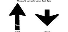
toward designated routes or destinations. Figure 2D-2 shows the
up-arrow and the down-arrow designs that have been approved for
use on guide signs. Detailed drawings of these arrows are shown
in the "Standard Highway Signs" book (see Section
1A.11).
Figure 2D-2 Arrows for Use on Guide Signs

Standard:
On overhead signs where it is desirable to indicate a lane to be
followed, a down arrow shall point downward toward the center of
that lane. Down arrows shall be used only on overhead guide signs
that restrict the use of specific lanes to traffic bound for the
destination(s) and/or route(s) indicated by these arrows. Down arrows
shall not be used unless an arrow can be pointed to each lane that
can be used to reach the destination shown on the sign.
Where a roadway is leaving the through lanes, an up arrow shall point upward at an angle representative of the alignment of the exit roadway.
Guidance:
Arrows used on guide signs to indicate the directions toward designated
routes or destinations should be pointed at the appropriate angle
to clearly convey the direction to be taken. A horizontally oriented
up-arrow design should be used at right-angle intersections.
On a ground-mounted guide sign, a directional arrow for a straight-through movement should point upward. For a turn, the arrow on a guide sign should point upward and at an angle related to the sharpness of the turn.
Option:
Arrows may be placed below the principal sign legend or on the appropriate
side of the legend.
Guidance:
At an exit, an arrow should be placed at the side of the sign which
will reinforce the movement of exiting traffic. The up-arrow design
should be used.
The width across the arrowhead should be at least equal to the height of the largest letter on the sign. For short downward pointing arrows on overhead signs, the width across the arrowhead should be 1.75 times the letter height.
Diagrammatic signing used on conventional roads should follow the principles set forth in Section 2E.19.
Section 2D.09 Numbered Highway Systems
Support:
The purpose of numbering and signing highway systems is to identify
routes and facilitate travel.
The Interstate and United States (U.S.) highway systems are numbered by the American Association of State Highway and Transportation Officials (AASHTO) upon recommendations of the State highway organizations because the respective States own these systems. State and County road systems are numbered by the appropriate authorities.
The basic policy for numbering the U.S. and Interstate highway systems is contained in the following Purpose and Policy statements published by AASHTO (see Addresses for AASHTO's address):
- "Establishment and Development of United States Numbered Highways"; and
- "Establishment of a Marking System of the Routes Comprising the National System of Interstate and Defense Highways."
Guidance:
The principles of these policies should be followed in establishing
the above highway systems and any other systems, with effective
coordination between adjacent jurisdictions. Care should be taken
to avoid the use of numbers or other designations that have been
assigned to Interstate, U.S., or State routes in the same geographic
area. Overlapping numbered routes should be kept to a minimum.
Standard:
Route systems shall be given preference in this order: Interstate,
United States, State, and County. The preference shall be given
by installing the highest-priority legend on the top or the left
of the sign panel.
Section 2D.10 Route Signs and Auxiliary Signs
Standard:
All numbered highway routes shall be identified by route signs and
auxiliary signs.
The signs for each system of numbered highways, which are distinctive in shape and color, shall be used only on that system and the approaches thereto.
Route signs and any auxiliary signs that accompany them shall be retroreflective.
Option:
Route signs and auxiliary signs may be proportionally enlarged where
greater legibility is needed.
Support:
Route signs are typically mounted in assemblies with auxiliary signs.
Section 2D.11 Design of Route Signs
Standard:
The "Standard Highway Signs" book (see Section
1A.11) shall be used for designing route signs. Other route
sign designs shall be established by the authority having jurisdiction.
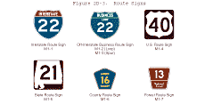
Interstate Route signs (see Figure 2D-3) shall consist of a cutout shield, with the route number in white letters on a blue background, the word INTERSTATE in white capital letters on a red background, and a white border. This sign shall be used on all Interstate routes and in connection with route sign assemblies on intersecting highways.
A 600 x 600 mm (24 x 24 in) minimum sign size shall be used for Interstate route numbers with one or two digits, and a 750 x 600 mm (30 x 24 in) minimum sign size shall be used for Interstate route numbers having three digits.
Figure 2D-3 Route Signs

Option:
Interstate Route signs may contain the State name in white upper-case
letters on a blue background.
Standard:
Off-Interstate Business Route signs (see Figure 2D-3) shall consist
of a cutout shield carrying the number of the connecting Interstate
route and the words BUSINESS and either LOOP or SPUR in capital
letters. The legend and border shall be white on a green background,
and the shield shall be the same shape and dimensions as the Interstate
Route sign. In no instance shall the word INTERSTATE appear on the
Off-Interstate Business Route sign.
Option:
The Off-Interstate Business Route sign may be used on a major highway
that is not a part of the Interstate system, but one that serves
the business area of a City from an interchange on the system. When
used on a green guide sign, a white square or rectangle may be placed
behind the shield to improve contrast.
Standard:
U.S. Route signs (see Figure 2D-3) shall consist of black numerals
on a white shield surrounded by a black background without a border.
This sign shall be used on all U.S. routes and in connection with
route sign assemblies on intersecting highways.
A 600 x 600 mm (24 x 24 in) minimum sign size shall be used for U.S. route numbers with one or two digits, and a 750 x 600 mm (30 x 24 in) minimum sign size shall be used for U.S. route numbers having three digits.
State Route signs shall be designed by the individual State highway agencies.
Guidance:
State Route signs (see Figure 2D-3) should
be rectangular and should be approximately the same size as the
U.S. Route sign. State Route signs should also be similar to the
U.S. Route sign by containing approximately the same size black
numerals on a white area surrounded by a black background without
a border. The shape of the white area should be circular in the
absence of any determination to the contrary by the individual State
concerned.
Standard:
If County road authorities elect to establish and identify a special
system of important County roads, a statewide policy for such signing
shall be established that includes a uniform numbering system to
uniquely identify each route. The County Route (M1-6) sign (see
Figure 2D-3) shall consist of a pentagon shape with a yellow County
name and route number and border on a blue background. County Route
signs displaying two digits or the equivalent (letter and numeral,
or two letters) shall be a minimum size of 450 x 450 mm (18 x 18
in); those carrying three digits or the equivalent shall be a minimum
size of 600 x 600 mm (24 x 24 in).
If a jurisdiction uses letters instead of numbers to identify routes, all references to numbered routes in this Chapter shall be interpreted to also include lettered routes.
Guidance:
If used with other route signs in common assemblies, the County
Route sign should be of a size compatible with that of the other
route signs.
Option:
When used on a green guide sign, a yellow square or rectangle may
be placed behind the County Route sign to improve contrast.
Standard:
Route signs (see Figure 2D-3) for park and forest roads shall be
designed with adequate distinctiveness and legibility and of a size
compatible with other route signs used in common assemblies.
Section 2D.12 Design of Route Sign Auxiliaries
Standard:
Route sign auxiliaries carrying word legends, except the JCT sign,
shall have a standard size of 600 x 300 mm (24 x 12 in). Those carrying
arrow symbols, or the JCT sign, shall have a standard size of 525
x 375 mm (21 x 15 in). All route sign auxiliaries shall match the
color combination of the route sign that they supplement.
Guidance:
Auxiliary signs carrying word messages and mounted with 750 x 600
mm (30 x 24 in) Interstate Route signs should be 750 x 375 mm (30
x 15 in). With route signs of larger sizes, auxiliary signs should
be suitably enlarged, but not such that they exceed the width of
the route sign.
Option:
A route sign and any auxiliary signs used with it may be combined
on a single panel.
Section 2D.13 Junction Auxiliary Sign (M2-1)
Standard:
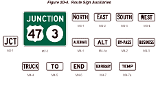
The Junction (M2-1) auxiliary sign (see Figure 2D-4) shall carry
the abbreviated legend JCT and shall be mounted at the top of an
assembly (see Section 2D.27)
either directly above the route sign or above a sign for an alternative
route (see Section 2D.16) that is part
of the route designation. The minimum size of the Junction auxiliary
sign shall be 525 x 375 mm (21 x 15 in) for compatibility with auxiliary
signs carrying arrow symbols.
Figure 2D-4 Route Sign Auxiliaries

Section 2D.14 Combination Junction Sign (M2-2)
Option:
As an alternative to the standard Junction assembly where more than
one route is to be intersected or joined, a rectangular sign may
be used carrying the word JUNCTION above the route numbers.
Other designs may be used to accommodate State and County Route signs.
Standard:
The Combination Junction (M2-2) sign (see Figure 2D-4) shall have
a green background with white border and lettering for the word
JUNCTION.
Guidance:
Where U.S. or State Route signs are used as components of guide
signs, only the outline of the shield or other distinctive shape
should be used.
Although the size of the Combination Junction sign will depend on the number of routes involved, the numerals should be large enough for clear legibility and should be of a size comparable with those in the individual route signs.
Section 2D.15 Cardinal Direction Auxiliary Signs (M3-1 through M3-4)
Guidance:
Cardinal Direction auxiliary signs (see Figure 2D-4) carrying the
legend NORTH, EAST, SOUTH, or WEST should be used to indicate the
general direction of the entire route.
Standard:
To improve the readability, the first letter of the cardinal direction
words shall be ten percent larger, rounded up to the nearest whole
number size.
If used, the Cardinal Direction auxiliary sign shall be mounted directly above a route sign or an auxiliary sign for an alternative route.
Section 2D.16 Auxiliary Signs for Alternative Routes (M4 Series)
Option:
Auxiliary signs, carrying legends such as ALTERNATE, BY-PASS, BUSINESS,
or TRUCK, may be used to indicate an alternate route of the same
number between two points on that route.
Standard:
If used, the auxiliary signs for alternative routes shall be mounted
directly above a route sign.
Section 2D.17 ALTERNATE Auxiliary Signs (M4-1, M4-1a)
Option:
The ALTERNATE (M4-1) or the ALT (M4-1a) auxiliary sign (see Figure
2D-4) may be used to indicate an officially designated alternate
routing of a numbered route between two points on that route.
Standard:
If used, the ALTERNATE or ALT auxiliary sign shall be mounted directly
above a route sign.
Guidance:
The shorter (time or distance) or better-constructed route should
retain the regular route number, and the longer or worse-constructed
route should be designated as the alternate route.
Section 2D.18 BY-PASS Auxiliary Sign (M4-2)
Option:
The BY-PASS (M4-2) auxiliary sign (see Figure 2D-4) may be used
to designate a route that branches from the numbered route through
a City, bypasses a part of the City or congested area, and rejoins
the numbered route beyond the City.
Standard:
If used, the BY-PASS auxiliary sign shall be mounted directly above
a route sign.
Section 2D.19 BUSINESS Auxiliary Sign (M4-3)
Option:
The BUSINESS (M4-3) auxiliary sign (see Figure 2D-4) may be used
to designate an alternate route that branches from a numbered route,
passes through the business portion of a City, and rejoins the numbered
route beyond that area.
Standard:
If used, the BUSINESS auxiliary sign shall be mounted directly above
a route sign.
Section 2D.20 TRUCK Auxiliary Sign (M4-4)
Option:
The TRUCK (M4-4) auxiliary sign (see Figure 2D-4) may be used to
designate an alternate route that branches from a numbered route,
when it is desirable to encourage or require commercial vehicles
to use the alternate route.
Standard:
If used, the TRUCK auxiliary sign shall be mounted directly above
a route sign.
Section 2D.21 TO Auxiliary Sign (M4-5)
Option:
The TO (M4-5) auxiliary sign (see Figure 2D-4) may be used to provide
directional guidance to a particular road facility from other highways
in the vicinity (see Section 2D.32).
Standard:
If used, the TO auxiliary sign shall be mounted directly above a
route sign or an auxiliary sign for an alternative route.
Section 2D.22 END Auxiliary Sign (M4-6)
Guidance:
The END (M4-6) auxiliary sign (see Figure 2D-4) should be used where
the route being traveled ends, usually at a junction with another
route.
Standard:
If used, the END auxiliary sign shall be mounted either directly
above a route sign or above a sign for an alternative route that
is part of the designation of the route being terminated.
Section 2D.23 TEMPORARY Auxiliary Signs (M4-7, M4-7a)
Option:
The TEMPORARY (M4-7) or the TEMP (M4-7a) auxiliary sign (see Figure
2D-4) may be used for an interim period to designate a section of
highway that is not planned as a permanent part of a numbered route,
but that connects completed portions of that route.
Standard:
If used, the TEMPORARY or TEMP auxiliary sign shall be mounted either
directly above the route sign, above a Cardinal Direction sign,
or above a sign for an alternate route that is a part of the route
designation.
TEMPORARY or TEMP auxiliary signs shall be promptly removed when the temporary route is abandoned.
Section 2D.24 Temporary Detour and Auxiliary Signs
Support:
Chapter 6F contains information regarding Temporary Detour and Auxiliary
signs.
Section 2D.25 Advance Turn Arrow Auxiliary Signs (M5-1, M5-2)
Standard:
If used, the Advance Turn Arrow auxiliary sign (see Figure 2D-5)
shall be mounted directly below the route sign in Advance Route
Turn assemblies, and displays a right or left arrow, the shaft of
which is bent at a 90-degree angle (M5-1) or at a 45-degree angle
(M5-2).
Figure 2D-5 Directional Arrow Auxiliary Signs

